Lincoln VSG-KR User manual

Subject to modifications
Owner’sManual
Operating Instructions and Spare Parts Lists
Page 1 of 14
1.2A-28001-C05
LINCOLN GmbH & Co. KG • Postfach 1263 • D-69183 Walldorf • Tel +49 (6227) 33-0 • Fax +49 (6227) 33-259
Two-line Lubricant Metering Devices
Model VSG-KR / VSL-KR
4289a00

Owner’sManual
Operating Instructions and Spare Parts Lists
Page 2 of 14
1.2A-28001-C05
Subject to modifications
LINCOLN GmbH & Co. KG • Postfach 1263 • D-69183 Walldorf •Tel +49 (6227) 33-0 • Fax +49 (6227) 33-259
General Information
Appropriate Use
Use the two-line metering devices of the VSG/VSL series only
for the supply of lubricant in centralized lubrication systems.
Geeneral Safety Instructions
Do not install or remove the metering devices when the
system is under pressure or the pump in operation.
•
Always protect the centralized lubrication system
connected to the pump with a pressure reducing valve.
•
Incorrect operation may lead to damage resulting from
insufficient or excessive lubrication of bearings or
lubrication points.
•
Your own alterations or modifications of an installed
sy stem should only be carried out if approved with the
manufacturer or his appointed dealer.
•
Use only original LINCOLN spare parts or parts
authorized by LINCOLN
Regulations for Prevention of Accidents
•Adhere to the rules valid in the country where the unit
will be in operation.
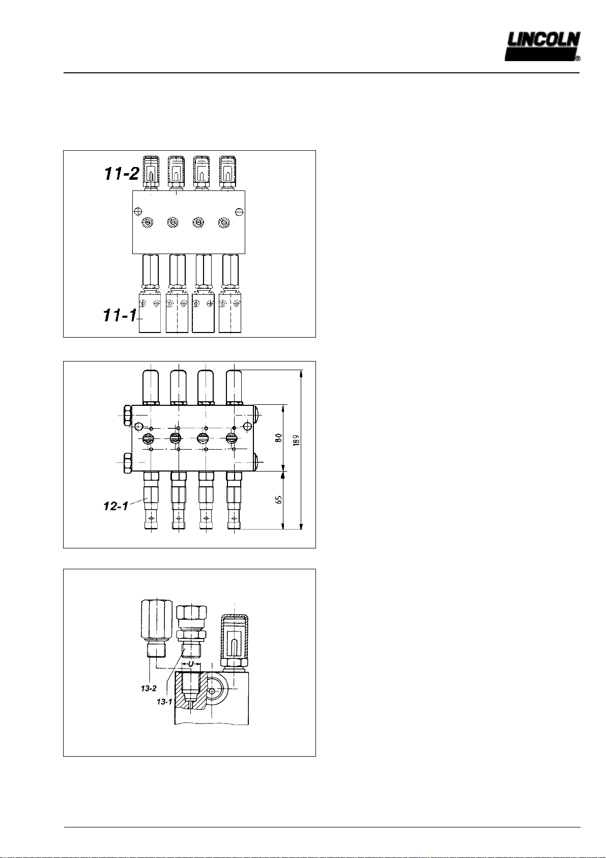
Installation
For all work at the metering device, observe extreme
cleanliness
–Attach the metering devices to even surfaces without
tension.
When base plates are used (see Accessories), first weld
the base plates without the metering devices and then
attach the metering devices onto them.
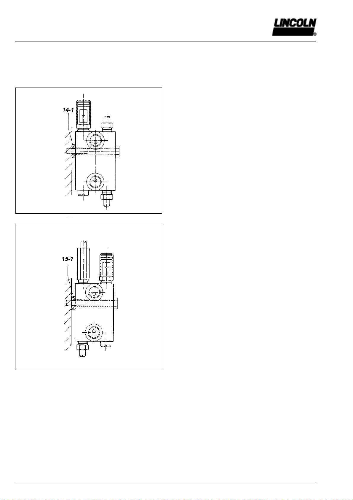
–Protect the metering devices from dust and influences of
heat (observe the maximum admissible operating
temperatures).
– The metering devices must be easily accessible for.
check and installation work.
·Before connecting the feed lines to the metering
devices, fill them with lubricant.
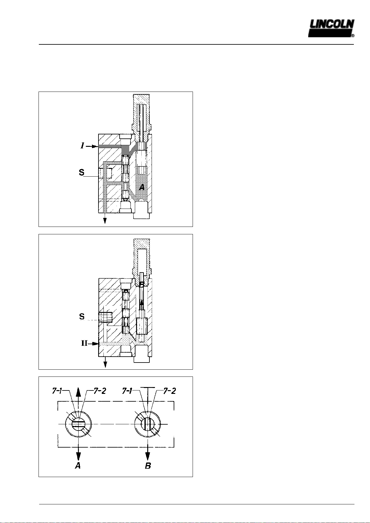
·When connecting the main lines take care to always
connect the same line (I or II) to the same metering
device inlet.
This makes it easier to check of the metering device
because all indicator pins are either in or out after each
cycle.
Table of Contents Page
General information................................................................ 2
Technical data ........................................................................ 3
Model identification................................................................. 5
Description of operation.......................................................... 6
Installation ............................................................................ 10
Accessories ...........................................................................11
Spare parts ........................................................................... 12
Operation, Maintenance and Repair
Repairs should be carried out only by qualified persons who
have been charged with the repair work and are familiar with
centralized lubrication systems.
Since the pistons in the metering devices are fit with the
smallest tolerances, the metering device must be replaced
when the pistons are worn.
When synthetic lubricants are used, bear in mind that they
must be compatible with the sealing material of the metering
devices (polyurethane or FKM).
Use only lubricants which are appropriate for centralized
lubrication systems. If in doubt, ask the supplier.
Further Information:
For the VSG-MR version:
Adjusting device with magnetically operated indication of
function (1.2A-18002-A96)
For the VSG-KR-NP version:
Data sheet „Piston detector“ (9.3A-20016-A00)

Subject to modifications
Owner’sManual
Operating Instructions and Spare Parts Lists
Page 3 of 14
1.2A-28001-C05
LINCOLN GmbH & Co. KG • Postfach 1263 • D-69183 Walldorf • Tel +49 (6227) 33-0 • Fax +49 (6227) 33-259
Technical Data:
Output volume: Q = 0-2,2 cm
3
/stroke, adjustable
Operating pressure: p
max
= 400 bar,
p
min
= 35 bar
Main line connection: G
3
/
8
Feed line connection: G
1
/
4
Technical Data VSG-KR
TYPE VSG2-KR VSG4-KR VSG6-KR VSG8-KR
Number of outlets 2 4 6 8
L1 (mm) 30,5 62 94 126
L (mm) 44,5 76 108 140
Part no. 620-40015-1 620-40015-3 620-40015-5 620-40015-7
4290a00

Owner’sManual
Operating Instructions and Spare Parts Lists
Page 4 of 14
1.2A-28001-C05
Subject to modifications
LINCOLN GmbH & Co. KG • Postfach 1263 • D-69183 Walldorf •Tel +49 (6227) 33-0 • Fax +49 (6227) 33-259
Technical Data VSL-KR
Technical Data:
Output volume: Q = 0-5 cm
3
/stroke, adjustable
Operating pressure: p
max
= 400 bar,
p
min
= 35 bar
Maine line connection: G
3
/
8
Feed line connection: G
1
/
4
TYPE VSL2-KR VSL4-KR VSL6-KR VSL8-KR
Number of outlets 2 4 6 8
L1 (mm) 30,5 62 94 126
L (mm) 44,5 76 108 140
Part no. 620-40062-3 620-40062-7 620-40064-3 620-40064-7
4291a00

Subject to modifications
Owner’sManual
Operating Instructions and Spare Parts Lists
Page 5 of 14
1.2A-28001-C05
LINCOLN GmbH & Co. KG • Postfach 1263 • D-69183 Walldorf • Tel +49 (6227) 33-0 • Fax +49 (6227) 33-259
VSG/VSL Idendification Chart
Examples of type designations: VSG 2 - D 1,1
VSL 8- KRFKMprotection cap MS
VSG 6 KR - NP
VSG VA 3 - KR VA
VSG 4 - KR - KNTU - A
VSG 1 - MR
VSL 8 - KR - KSC
Basic type
G : Max. output volume 2,2 cm³
L : Max. output volume 5 cm³
Standard version
Steel body, galvanized
VA : stainless body 1.4305
Number of outlets 1 to 8
Adjusting of output and monitoring
KR: with indicator pin and progressive adjustment
KD: with indicator pin and metering screws
D : with metering screws (output volume in cm³)
MR: adjustment with magnetically operated indication
Adjusting:
Standard version: steel, galvanized
VA : stainless steel 1.4305
FKM: adjustment with FKM seal (over 80°C)
(standard: polyurethane)
KN : with indicator pin and progressive adjustment
as well as fitted proximity switch per pair
of outlets
KA : with indicator pin and adapter
(proximity switch to be supplied by customer)
KS : with indicator pin and progressive adjustment
as well as fitted limit switch per pair of outlets
NP : with integrated proximity switch
(piston detector)
Protection cap MS: Protection cap brass
C,TU : internal abbreviations
A : USA-version (NPT thread)
Note: The metering devices model D and KD are supplied
with metering screws for maximum output (2.2 or 5 cm
3
)
when no other specification is indicated.

Owner’sManual
Operating Instructions and Spare Parts Lists
Page 6 of 14
1.2A-28001-C05
Subject to modifications
LINCOLN GmbH & Co. KG • Postfach 1263 • D-69183 Walldorf •Tel +49 (6227) 33-0 • Fax +49 (6227) 33-259
Fig. 3
Description of Operation
Model VSG, VSL Metering Devices
Fig. 1
Fig. 4
1122a95
1124a95
1125a95
1123a95
Fig. 2
Stage 1
Pressurised lubricant is supplied to the metering device via
main line I. The control piston (1) starts moving in the direc-
tion of arrow A, displacing the lubricant in front of the control
piston into the relieved main line II.
Stage 2
When the control piston (1) uncovers the connecting passage
(2) lubricant is transferred to the right end of the dispensing
piston (3), thereby displacing it to the left in the direction of
arrow A.
The lubricant volume ahead of the dispensing piston is
transferred via the connection passage (4) to the lubrication
point. With the dispensing piston in its terminal position, the
pressure in main line I will continue to rise to reach the preset
change-over pressure of the two-line system. At this stage,
the change-over valve of the system operates to connect
main line I which has so far been under pressure to the
lubricant reservior of the lubrication pump and the lubricant in
main line I is depressurized.
Stage 3
At the same time the change-over valve connects main line II
to the lubrication pump, thus pressurizing the lubricant in this
main linc. The control piston (1) moves in the direction of
arrow B, displacing the lubricant ahead of the control piston
into the relieved main line I.
Stage 4
When the control piston (1) uncovers the connecting passage
(5) lubricant is transferred to the left end of the dispensing
piston (3) and displaces it to the right in the direction of arrow
B. The lubricant ahead of the dispensing piston (3) is trans-
ferred via the connecting passage (6) to the lubrication point.
With the dispensing piston (3) in its terminal position, the
pressure in main line II will continue to rise to reach the
preset change-over pressure of the two-line system. At this
stage, the change-over valve will once again cause a pressu-
re changing-over in main lines I and II and the cycle will be
repeated as described in stage 1.

Subject to modifications
Owner’sManual
Operating Instructions and Spare Parts Lists
Page 7 of 14
1.2A-28001-C05
LINCOLN GmbH & Co. KG • Postfach 1263 • D-69183 Walldorf • Tel +49 (6227) 33-0 • Fax +49 (6227) 33-259
Fig. 5
Model VSG, VSL Metering Devices
Fig. 6
1126a95
1127a95
1131a95
Fig. 7
Cross-porting of outlets
This feature enables one outlet only of a pair of outlets to be
used, and provides double the lubricant volume output per
lubrication cycle.
Figure 5 shows stage 2 and figure 6 shows stage 4 of the
operation cycle with this feature operative. All models of the
series VSG and VSL are equipped with a lockable rotary slide
for each pair of outlets.
Position of cross-porting rotary slide
7-1 lock screw
7-2 rotary slide horizontal: 2 outlets
rotary slide vertical: 1 outlet
With the two main lines being relieved (i.e. when the pump is
switched of) the lock screw 7-1 can be lossened and the
rotary slide 7-2 can be turned through 90°. If the rotary slide
is put into position A the connecting passage between the two
outlets is closed, and the lubricant is discharged by the two
outlets. If the rotary slide is in position B, the connecting
passage is open. In this case one of the two outlets has to be
closed by means of a closure plug, and then the double
lubricant volume is discharged by the other outlet (Table 1).

Owner’sManual
Operating Instructions and Spare Parts Lists
Page 8 of 14
1.2A-28001-C05
Subject to modifications
LINCOLN GmbH & Co. KG • Postfach 1263 • D-69183 Walldorf •Tel +49 (6227) 33-0 • Fax +49 (6227) 33-259
Fig. 10
Fig. 9
Fig. 8 1128b95
1129a95 1130b95
Adjustment of the Output Volume
Adjustment of the output volume: VSG-KR Adjustment of the output volume: VSL-KR
Revolutions of the adjusting screw
Outputvolume cm³/stroke
4292a00 4293a00
Variation KR for infinitely variable adjustment and visual
indication
Infinitely variable adjustment of lubricant output is achieved
by turning the adjustment screw 8-2. Maximum output is
available if the lock screw 8-1 and the adjustment screw 8-2
are in their uppermost position. By turning the screw down-
ward the output can be contintinuously reduced. With the two
screws in their fully closed position, the indicator pin 8-3 is
completely restrained and, because the pin is attached
directly to the dispensing piston, the lubricant output will be
nearly zero.
The indicator pin shows the correct functioning of a pair of
outlets. After setting the lubricant output, the adjustment
screw 8-2 will be locked in position by means of screw 8-1.
To secure the setting, lock the
adjusting screw only when the
indicator pin is retracted.
Revolutions of the adjusting screw
Outputvolume cm³/stroke
D and KD variants for graded adjustment of the output
volume
All metering devices of the VS series can also be supplied
with metering screws as version D (fig. 9) or with metering
screws and indicator pin for visual indication as version KD
(fig. 10). The interchangeable metering screws limit the stroke
of the delivery piston. The longer the metering screw is, the
smaller the output volume will be.
For each series there are four metering screws (table 2)
which must be ordered separately. The metering devices are
supplied with metering screws for the maximum output
delivery if no other specification is mentioned on ordering.
The D variant is recommended for extreme conditions of
operation: high temperatures or aggressive media.

Subject to modifications
Owner’sManual
Operating Instructions and Spare Parts Lists
Page 9 of 14
1.2A-28001-C05
LINCOLN GmbH & Co. KG • Postfach 1263 • D-69183 Walldorf • Tel +49 (6227) 33-0 • Fax +49 (6227) 33-259
1132b95
Fig. 11
Fig. 13 1133b95
Fig.12 4294b00
KS variant
Visual indication and electric signal.
The metering devices of the VSG and VSL series can be
equipped with limit switches 11-1 for the remote monitoring of
operation of two outlets each. The stroke movement of the
delivery piston is transmitted to the limit switch.
Since these metering devices with fitted limit switch are also
equipped with the visual indication 11-2 shown in fig. 8, it is
easy to find out the malfunctioning pair of outlets in case of a
defect.
KR-NP variant
The VSG metering devices can be supplied with a piston
detector (item 12-1) for electronic monitoring.
The proximity switch is activated directly via the respective
delivery piston, without contact and wear.
The minimum output volume is 0.4 cm
3
for this version.
For feed lines in every length, use the screw-type couplings
with cutting ring 13-1 which can be completed with the
adapter 13-2 in case of difficult conditions of assembly (table 3).
These couplings make it possible to connect the feed lines
and the branch lines from both main lines to the VSG and
VSL metering devices.
Check valves for VS metering devices
In case of high counter-pressures it is recommended to install
check valves in the metering device outlets (table 5).
These are found for example in download progressive
metering devices.

Owner’sManual
Operating Instructions and Spare Parts Lists
Page 10 of 14
1.2A-28001-C05
Subject to modifications
LINCOLN GmbH & Co. KG • Postfach 1263 • D-69183 Walldorf •Tel +49 (6227) 33-0 • Fax +49 (6227) 33-259
Fig. 14 1134b95
1135b95
Fig. 15
Installation of VS metering devices
All metering devices may be mounted in any position, so that
the indicator pins may point upward, downward, to the right
or to the left. To simplify the illustration, fig. 14 and 15 only
show the indicator pin pointing upward.
The metering devices can further be installed in such a way
that the outlets are in front of the indicator pin (fig. 14) or
behind it (fig. 15). The installation shown on fig. 15 has the
advantage that the indicator pins cannot be partially covered
by the feed lines.
The difficulty of connecting the tube lines with this arrange-
ment can be avoided by using the adapters 13-2 (table 3).
Possible distortions of the metering devices can be avoided
by using flexible spacers (14-1 and 15-1). These spacers
ensure trouble-free operation of the metering devices even
when they are installed on uneven surfaces (table 4).
The VS metering devices with fitted limit switch must in
addition be installed with spacers.
Moreover, it is recommended to install them with the feed
lines ahead of the limit switches and thus ahead of the
indicator pins.

Subject to modifications
Owner’sManual
Operating Instructions and Spare Parts Lists
Page 11 of 14
1.2A-28001-C05
LINCOLN GmbH & Co. KG • Postfach 1263 • D-69183 Walldorf • Tel +49 (6227) 33-0 • Fax +49 (6227) 33-259
Table 3:
Adapter for male connectors acc. to fig 12 (12 - 2)
Table 1:
Closure plugs for metering devices with 1 outlet per adjustment
Series Thread Part number
VSG/VSL R1/4” 303-17526-2
Metering device Part number
VSG Adapter 420-22139-1
R 1/4”m. x R 1/4”f. Z
VSL Adapter 420-22140-1
R 1/4”m. x R 1/4”f. Z
Table 2:
Metering screws for KD and D variants acc. to fig. 9 and 10 Table 4:
Flexible spacers acc. to fig. 13 and 14
Metering Attaching Spacer Part number
device borehole
VSG/VSL DIA 9 8.5 x 18 x 5 421-21288-1
Series Marked volumes Part number
cm
3
/stroke
VSG 0.55 303-17505-1
1.10 303-17506-1
1.65 303-17507-1
2.2 303-17508-1
VSL 1.25 303-17509-1
2.50 303-17510-1
3.75 303-17511-1
5.00 303-17512-1
Accessories
Table 5:
Check valves for outlets
Tube DIA Designation Part number
6mm GERV 6 - S G 1/4A VC 223-13052-1
8mm GERV 8 - L G 1/4A VC 223-13052-2
10mm GERV 10-L G 1/4A VC 223-13052-3

Owner’sManual
Operating Instructions and Spare Parts Lists
Page 12 of 14
1.2A-28001-C05
Subject to modifications
LINCOLN GmbH & Co. KG • Postfach 1263 • D-69183 Walldorf •Tel +49 (6227) 33-0 • Fax +49 (6227) 33-259
VSG-KR Spare Parts List
Item Description Part no.
1 Closure plug M10 x 1 303-17404-1
2 Copper washer 5 x 9 x 1 209-12158-8
3 Closure plug R1/4” 303-17515-1
4 Copper washer 13.5 x 16 x 1 306-17827-1
5 Holding screw M8 x 1 420-22350-1
6 Indicator pin assy. 520-32066-1
7* Adjusting sleeve with U-cup
sealing ring AU (standard) 520-31488-2
Adjusting sleeve with U-cup
sealing ring FKM 520-31899-2
8 O-ring 12 x 2 219-12223-5
9 Protection cap 420-24818-1
Adjusting device assy. AU (items 7 + 9) 520-34011-1
Adjusting device assy. FKM (items 7 + 9) 520-34011-2
10 Screw ring M 10 x 1 303-17552-2
11 O-ring 6 x 2 219-12451-5
12 Closure plug 303-17526-2
*includ. item. 8 (O-ring 12 x 2)
Fig. 16 4295a00

Subject to modifications
Owner’sManual
Operating Instructions and Spare Parts Lists
Page 13 of 14
1.2A-28001-C05
LINCOLN GmbH & Co. KG • Postfach 1263 • D-69183 Walldorf • Tel +49 (6227) 33-0 • Fax +49 (6227) 33-259
Ersatzteilliste VSL-KR
Fig. 17 4296a00
Item Description Part no.
1 Closure plug M 10 x 1 303-17404-1
2 Copper washer 5 x 9 x 1 209-12158-8
3 Closure plug M 16 x 1.5 303-17514-1
4 Copper washer 16 x 19 x 1 306-18754-1
5 Holding screw M 8 x 1 420-22350-1
6 Indicator pin assy. 520-32065-1
7* Adjusting sleeve with U-cup
sealing ring AU (standard) 520-31487-2
Adjusting sleeve with U-cup
sealing ring FKM 520-31898-2
8 O-ring 12 x 2 219-12223-5
9 Protection cap 420-22136-2
Adjusting device assy. AU (items 7 + 9) 520-34011-4
Adjusting device assy. FKM (items 7 + 9) 520-34011-5
10 Screw ring M 10 x 1 303-17552-2
11 O-ring 6 x 2 219-12451-5
12 Closure plug 303-17526-2
*includ. item. 8 (O-ring 12 x 2)

Owner’sManual
Operating Instructions and Spare Parts Lists
Page 14 of 14
1.2A-28001-C05
Subject to modifications
LINCOLN GmbH & Co. KG • Postfach 1263 • D-69183 Walldorf •Tel +49 (6227) 33-0 • Fax +49 (6227) 33-259
Declaration by the
manufacturer as defined by machinery
directive 89/392/EEC Annex II B
Herewith we declare that the supplied model of
Metering Device Typ VS...
is intended to be incorporated into machinery covered by this
directive and must not be put into service until the machinery
into which it is to be incorporated has been declared in confor-
mity with the provisions of the directive.
Applied harmonized standards in particular
EN 292 T1/T2
prEN 809
Walldorf, December 1994, ppa. Z. Paluncic
This manual suits for next models
1
Table of contents
Other Lincoln Dispenser manuals
Popular Dispenser manuals by other brands

Stalgast
Stalgast 383190 user manual

Taylor
Taylor R160 manual

Ratiomed
Ratiomed MEG 289.1020 quick start guide

Tuthill
Tuthill FILL-RITE FR102PHU Owners installation, operation, and safety manual

VOCA
VOCA TC-X Installation instruction

Curtis
Curtis TLP10 Installation instructions, service & warranty information

Cornelius
Cornelius HELIX installation manual

Cornelius
Cornelius VIPER (E) 2 FLAVOR installation manual

Emerson
Emerson InSinkErator DS200 Quick installation and care guide

SCRUB TRAK
SCRUB TRAK VendNet 3597 Programming manual

Kimberly-Clark
Kimberly-Clark Suretouch installation instructions

RIVIAN
RIVIAN PT00401761 installation guide