Lindab Premum Series User manual

lindab | we simplify construction
© 04.2020 Lindab Ventilation. All forms of reproduction without written permission are forbidden. is the registered trademark of Lindab AB.
Lindab's products, systems, product and product group designations are protected by intellectual property rights (IPR).
LindabPremum / Premax
Active chilled beam
Installation instructions

2Lindab reserves the right to make changes without prior notice
2020-04-21
Lindab reserves the right to make changes without prior notice
2020-04-21
Installation instruction Premum/Premax
lindab | we simplify construction
1 Content and symbols
1.1 Content
1. Content and symbols..........................................2
1.1 Content....................................................................... 2
1.2 Symbols ..................................................................... 3
2. Control of delivery .............................................3
2.1 Before starting............................................................ 3
2.2 Safe operation............................................................ 3
2.3 Receipt of goods........................................................ 3
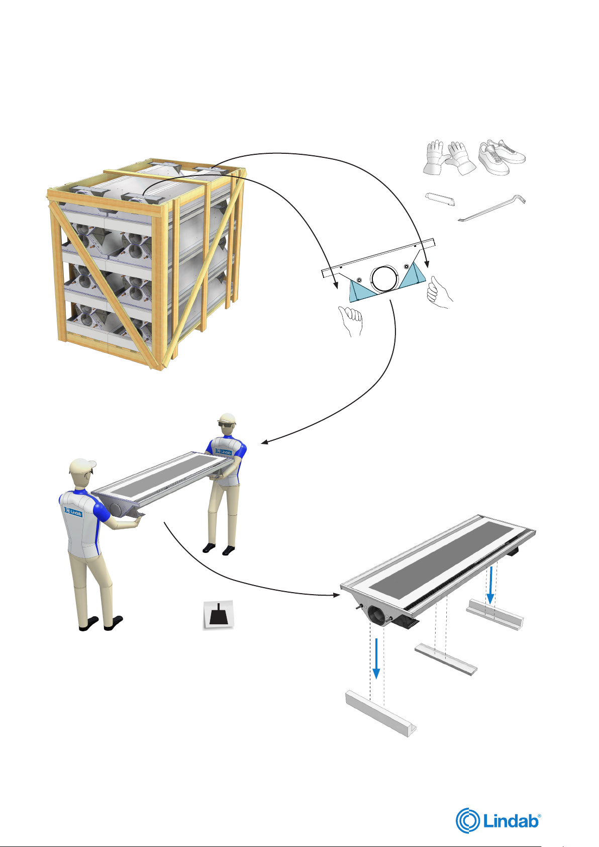
2.4 Unloading of goods....................................................3
2.5 Handling / Carrying.................................................... 3
2.6 Tools ........................................................................... 4
2.7 Installation .................................................................. 4
2.8 Where to find additional instructions or technical
documentation........................................................... 4
2.9 Cleaning after assembly/before commissioning....... 4
2.10 Packing, unpacking guideline .................................. 5
2.11 Product labelling....................................................... 6
2.12 Order code ............................................................... 7
2.13 Order code examples............................................... 7
2.14 Label ......................................................................... 7
2.15 Contents of order ..................................................... 8
2.16 Plus features............................................................. 8
2.16.1 Inlet faceplates....................................................... 8
2.16.2 Outlet front grilles........................................................ 8
2.16.3 Integrated valves ................................................... 8
2.16.4 Integrated Actuators.............................................. 8
2.16.5 Integrated Regula components............................. 8
2.16.6 Airguides................................................................ 8
2.16.7 Heating .................................................................. 8
2.17 Accessories .............................................................. 8
3. Product specification.........................................9
3.1 Product description.................................................... 9
3.2 Dimensions ................................................................ 9
3.3 Premum / Premax.................................................... 10
3.4 Material data ............................................................ 10
3.5 Environmental Declarations..................................... 10
3.6 Pressure class.......................................................... 10
3.7 Water quality ............................................................ 10
3.8 Air quality ................................................................. 10
3.9 Capacity test............................................................ 10
4 Connections ...................................................... 11
4.1 Water connections ................................................... 11
4.1.1 Befo re installation .................................................. 11
4.1.2 Push on fitting ....................................................... 12
4.1.3 Compression fitting............................................... 12
4.1.4 Flexible hoses........................................................ 12
4.1.5 Additional Lindab accessories for water
connections ........................................................... 13
4.1.6 Possible connections water cooling
(2-pipe, standard).................................................. 14
4.1.7 Possible connections water cooling and
heating (4-pipe, plus feature) ................................ 15
4.2. Air connections ....................................................... 16
4.2.1 Air connection installation..................................... 16
4.2.2 Possible connections supply air........................... 16
4.2.3 Possible connections extract air .......................... 16
4.3 Possible combination of connections ..................... 16
4.4 Electrical connections ............................................. 17
4.4.1 Regula components on the beam......................... 17
4.4.2 Example 1: Wiring scheme with Regula
Connect multi........................................................ 18
4.4.3 Example 2: Wiring scheme with Regula
Connect basic....................................................... 18
4.4.4 Regula Connect on the beam............................... 19
4.4.5 Regula Secura on the beam ................................. 19
4.4.6 Valves and Actuators on the beam....................... 19
4.4.7 Regula Combi on/with the beam .......................... 19
4.4.8 Actuators............................................................... 19
5 Installation of product.......................................20
5.1 Handling of product ................................................. 20
5.2 Ceiling systems........................................................ 20
5.3 General installation principles ................................. 21
5.3.1 Recessed in suspended T-bar ceiling .................. 21
5.3.2 Exposed, sealed to the ceiling ............................. 21
5.3.3 Exposed, free hanging.......................................... 21
5.3.4 Free hanging above perforated or eggcrate
ceiling .................................................................... 21
5.3.5 Recessed in suspended (permanent)
ceiling .................................................................... 21
5.3.6 Recessed in suspended (permanent) ceiling
without cover flanges............................................ 21
5.4 Preparation for installation on the product.............. 22
5.5 Basics steps of installing the product ..................... 24
6 Adjustment and commissioning........................25
6.1 Airflow and pressure ................................................ 25
6.1.1 Jet cone adjustment pins ...................................... 25
6.1.2 Finding values for JetCone pins ........................... 27
6.1.3 Adjusting air flow and pressure with JetCone
pins......................................................................... 27
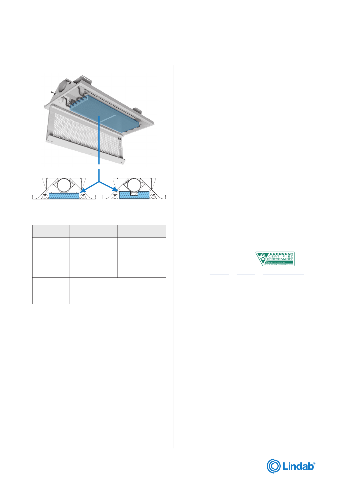
6.2 Adjustment of air distribution profile ....................... 29
6.3 Measuring air pressure and calculating the air
flow...........................................................................30
6.3.1 Measuring static nozzle pressure and air
pressure ................................................................30
6.3.2 Calculating the actual air flow .............................. 31
6.3.3 Changing the actual air flow ................................. 31
6.3.4 Changing the air distribution profile ..................... 31
6.3.5 Premum / Premax pressure / airflow diagrams ... 31
6.4 Water flow rate ......................................................... 32
6.4.1 Pre-setting of valves ............................................. 32
6.4.2 Balancing strategy ................................................ 32
7. Maintenance.....................................................33
7.1 Remove the outlet front grille ...................................33
7.2 Open inlet faceplate .................................................33
7.3 Opening inspection hatch........................................ 33
7.4 Lower battery ........................................................... 33
8 Accessories.......................................................34

33
10-25
kg !
10-25
kg !
Lindab reserves the right to make changes without prior notice
2020-04-21
Installation instruction Premum/Premax
lindab | we simplify construction
2 Control of delivery
2.1 Before starting
Read through the entire installation instruction before
commencing installation in order to determine which parts
that needs to be performed and in what order to be done.
Lindab is a supplier of complete water products, but we
offer also a wide range of accessories which suit perfectly
to our water products simplifying your installation work,
e.g. different type of hangers, Tektite-couplings, closing
valves, thermostatic valves and actuators, flexible hoses,
customized regulation components, customized cabeling
and more. See also the separate document “Accessories."
Lindab will also provide you with a full ventilation system,
with a wide range of Lindab Safe components. See also
“Air Duct Systems."
2.2 Safe operation
Beware of sharp edges, especially of the coils. Always
wear thin gloves and protective clothing.
All existing safety regulations must be observed when
working with Lindab water products. Check the weights
of the beams or the panels with the installation instruction
before carrying.
2.3 Receipt of goods
Start by checking that the delivery is complete accord-
ing to the order and that everything listed on the consign-
ment note has been delivered. Then carry out a review of
the products and make sure that nothing was damaged
during transportation. If you discover damage that has
occurred during delivery, it must be notified immediately.
Lindab is not responsible for costs associated with the
replacement of products, that have been installed in any
way other than shown in these installation instructions.
1.2 Symbols
Heavy Load - 2 man job -
It is recommended to use
a “lift” for mounting.
Hand-pull
Hot water
Cold water
Vacum cleaner Dust cleaner
2.4 Unloading of goods
The beams and panels are normally delivered packed
on wooden pallets. Lift the pallets carefully with a fork
lift and place them on a dry and plain surface/ground. If
the beams are delivered in single boxes, wooden blocks
should be placed on the ground at one-metre intervals (or
a pallet), before the boxes are been placed to store. Lind-
abs water products must be stored on a plane surface in
a dry and well ventilated place, preferably indoors. If they
have to be stored outdoors, protect them with a water-
proof cover and store them protected from rain beneath a
roof or other until they are fitted.
2.5 Handling / Carrying
The beam or panel must be handled with care, ensuring
that it will not be scratched or bended during transporta-
tion, preparation and installation.
Always carry the beams or panels piecewise into the build-
ing. Keep the product in the package as long as you can.
Never use piping connections or edges to lift them, neither
when you unpack them nor when you carry them towards
the construction site.
Do not place the product directly on the floor. Use the pro-
tective corners from package or other clean means from
package to place the product before installation.
Be careful if you must carry a long panel horizontally; if
the panels are bended lengthwise, the profiles may be
deformed and the piping could loosen from the panel.
When opening the box with a knife, be careful not to
damage the product.
Each beam is equipped with protective film to avoid any
damage during transportation and handling on building
site. The film needs to be removed before commissioning
the products.

4Lindab reserves the right to make changes without prior notice
2020-04-21
Lindab reserves the right to make changes without prior notice
2020-04-21
Installation instruction Premum/Premax
lindab | we simplify construction
2.6 Tools
To install the beam, panel or facade unit, the following tools are required.
2.7 Installation
It is important to use the correct hangers and the recom-
mended amount for all installation principles. Different
possible installation principles are shown in the installa-
tion instruction and hangers from Lindab should be used
to ensure, that they are intended for the purpose and are
safe to use.
Lindab´s water products can be ordered, to be adapted
to a wide range of different ceiling systems, please check
installation instruction to ensure best adaptation.
The Lindab water products should always be installed
separately hanged up from the recessed ceiling. The
weight of the product should not be covered by the ceiling
system.
Use plastic folio or other to protect the product during on
site construction continually to keep the products in best
condition and avoid any scratches.
2.8 Where to find additional instructions
or technical documentation
In the following chapters we will refer to additional tech-
nical documents or/and instructions by a certain keyword
written as a link.
If so you will easily find it with our Lindab Quick Selection
Tool: www.lindqst.com
1. Visit www.lindqst.com
2. Select “documentation finder”
3. Select keyword (product name)
4. Follow the link
5. Find your document under “Related documents”
2.9 Cleaning after assembly/ before
commissioning
Please remember to remove plastic folio and other protec-
tion material before commissioning and clean the product
before hand over.
Knife Tape measure
Pencil
Tectite tool 12mm
(Order no: 884087)
Spirit level
Dust-cleaner
Deburring tool Bits and drills
Gloves
Drill machine Spanner
Tectite tool small 12mm
(Order no: 646881)
Lindab PC410
(Order no: 103344)
Vacum cleaner
Shoes with soft soles
Percussion drill
Crowbar Screwdriver

5
10-25
kg !
Lindab reserves the right to make changes without prior notice
2020-04-21
Installation instruction Premum/Premax
lindab | we simplify construction
2.10 Packing, unpacking guideline

6
40
50
40
80
90
60
70
100
20 3025
150
10
[Pa]
[l/s]
50
01 2 345 6 7 8 9
159875 6
Premum/Premax Inregulation Diagram
2011-09-30
Lenhgt 1,2m -2,3m
Position
Premum / Premax 1,2m < L ≤ 2,0m Position of JetCone adjustment pins
1 3
2 4
Pos.
0-9
L
JetCones
Rev.Premum/Premax-04032016
Date Pstat [Pa] qa [l/s] 1 2 3 4
Signature
Order : xx-xxxxx
Project : xxxxxx xxxxxxxx
Mark : xxxxx
Nozzles : N/A
Product ID : xxxxxxx
Plugs : N/A Sign. :
Pos : xx
PREMUM X-XX-xx-125-xx-x,x-xx-xx
Pressure: AA Pa Flow: BB l/s
x,xx m
Lindab reserves the right to make changes without prior notice
2020-04-21
Lindab reserves the right to make changes without prior notice
2020-04-21
Installation instruction Premum/Premax
lindab | we simplify construction
2.11 Product labelling

7
Premum - I-60 - 12 - 125 - A1 - 2,5 - 60 - 15
Premax - I-60 - 15 - 125 - A1 - 2,4 - 60 - 15
Order : xx-xxxxx
Project : xxxxxx xxxxxxxx
Mark : xxxxx
Nozzles : N/A
Product ID : xxxxxxx
Plugs : N/A Sign. :
Pos : xx
PREMUM X-XX-xx-125-xx-x,x-xx-xx
Pressure: AA Pa Flow: BB l/s
x,xx m
Order : xx-xxxxx
Project : xxxxxx xxxxxxxx
Mark : xxxxx
Nozzles : xxx
Product ID : xxxxxxx
Plugs : xxx Sign. :
Pos : xx
PREMAX-x-xxx-xx-xxx-X
Pressure: AA Pa Flow: BB l/s
x,xx m
Order : xx-xxxxx
Project : xxxxxx xxxxxxxx
Mark : xxxxx
Nozzles : N/A
Product ID : xxxxxxx
Plugs : N/A Sign. :
Pos : xx
PREMUM X-XX-xx-125-xx-x,x-xx-xx
Pressure: AA Pa Flow: BB l/s
x,xx m
Premum/Premax
Order : xx-xxxxx
Project : xxxxxx xxxxxxxx
Mark : xxxxx
Nozzles : N/A
Product ID : xxxxxxx
Plugs : N/A Sign. :
Pos : xx
PREMUM X-XX-xx-125-xx-x,x-xx-xx
Pressure: AA Pa Flow: BB l/s
x,xx m
x 2
x 2
x 2
x 2
Premum X-XX 12 125 XX X,X XX XX
Ø12
(2 x 2) A1 A2 A3
A4 A7 A8
B1 B2 B3
B4 B7 B8
C3 C4
C7 C8
D3 D4
D7 D8
I-60*
I-62*
X-60*
125
Ø12/Ø15
(2 x 2)
Premax X-XX XX 125 XX X,X XX XX
Lindab reserves the right to make changes without prior notice
2020-04-21
Installation instruction Premum/Premax
lindab | we simplify construction
* As a plus feature the Premum/Premax Y-60 and Z-60 models can be ordered as well. See 3.2 for more details.
2.12 Order code
2.14 Label
On the label you’ll find:
• Order: Order identification number
• Pos.: Order position
• Product: Product configuration and product length
• Data: Preset static pressure and preset airflow
• Project: Project name
• Mark: Marking noted on order
• Product ID: Product number
• Sign: To be signed when checked and commissioned on site
2.13 Order code examples
Preset
static pressure
[Pa]
before nozzles
Product length
1,2 m - 3,6 m
I-60, I-62, X-60
in steps of 0,6 m
Product length
1,2 m - 3,6 m
I-60 and X-60
in steps of 0,1 m
I-62
in steps of 0,6 m
Preset
airflow
[l/s]

8
Rc LINK
LINDAB
N = Neutral
L = Load
S = Signal
RC in/out
CO2 in - S
CO2 in - S
CO2 out - N
CO2 out - L
Presence in - S
Presence in - S
Presence out - N
Presence out - L
Damper out - S
Damper out - N
Damper out - L
Heating out - S
Heating out - N
Heating out - L
Cooling out - S
Cooling out - N
Cooling out - L
Supply in - N
Supply in 24V - L
REGULA CONNECT
Heating in - S
Cooling in - S
Supply out - N
Supply out - L
Heating link - S
Cooling link - S
Supply link - N
Supply link - L
Heating link - S
Cooling link - S
Supply link - N
Supply link - L
Multi
Rc LINK
x4
M8
Lindab reserves the right to make changes without prior notice
2020-04-21
Lindab reserves the right to make changes without prior notice
2020-04-21
Installation instruction Premum/Premax
lindab | we simplify construction
Regula Combi Condensation sensor and Regula Secura
Regula Multi connect card
Presence sensor
Go to Actuators for details.
2.16.5 Integrated Regula components
Go to TTR/TTV water valves for details.
2.16.4 Integrated Actuators
2.15 Contents of order
Standard package/order contains:
• Beam
• Plus features (pre-installed in factory)
• 4 pc/beam of copper insets (separate in smaller box)
• Accessories (separate in smaller box)
2.16 Plus features
2.16.1 Inlet faceplates
Not relevant for Premum/Premax
2.16.2 Outlet front grilles
Not relevant for Premum/Premax
2.16.3 Integrated valves
2.16.6 Airguides
The Lindab AirGuide system offers readjustable air spread
pattern control. The AirGuide deflectors integrated in the
Premum/Prenax faceplate have 32 different settings. For
details see 6.2 .
2.16.7 Heating
Premum/Premax is in the stand-
ard version always equipped with a
cooling in/out "2-pipe connection."
The beams can be equipped with an
aditional heating circuit, providing a
heating function as well as cooling.
2.17 Accessories
Here are some general accessories. For full range see
separate Accessories document.
Go to Accessories for details.
Threaded rod kit
Order no: see Accessories
Flexible hoses
Order no: 680080 (0,4m push on, 12 and 12mm).
See Accessories
Transformer
Order no:
see Accessories
Tectite fittings
Order no: 647690, 884050 and 884014 (12mm)
see Accessories
Go to Regula for details.

9
A (L*)
B
Premum/Premax I-60 / I-62
Ø125
Premum 12mm
Premax 12/15mm
B BB
B/2B/2 B/2
40
40
10
Premum/Premax X-60
200
131
131
Premum/Premax Y-60 / Z-60
200
131
Lindab reserves the right to make changes without prior notice
2020-04-21
Installation instruction Premum/Premax
lindab | we simplify construction
3 Product specification
3.1 Product description
The Premum/Premax air beams are standardly prepared for ventilation and cooling (2-pipe connection). They are available
in ceiling system integrateable I-60, I-62 and X-60 models. As a plus feature also integrateable Y-60 and Z-60 models are
available.
3.2 Dimensions
PREMAX L* (mm) A (mm) B (mm) kg / m Ceiling type
I-60 1200, 1800, 2400, 3000, 3600 1192, 1792, 2392, 2992, 3592 592
18
1, 2
I-62 1200, 1800, 2400, 3000, 3600 1242, 1867, 2492, 3117, 3742 617 21, 22
X-60 1200, 1800, 2400, 3000, 3600 1199, 1799, 2399, 2999, 3599 599 3, 4, 5, 6, 7, 8, 14
PREMUM L* (mm) A (mm) B (mm) kg / m Ceiling type
I-60 1200 - 3600 (Steps of 100 mm) 1192 - 3592 (Steps of 100 mm) 592
15
1, 2,
I-62 1200, 1800, 2400, 3000, 3600 1242, 1867, 2492, 3117, 3742 617 21, 22
X-60 1200 - 3600 (Steps of 100 mm) 1199 - 3599 (Steps of 100 mm) 599 3, 4, 5, 6, 7, 8, 14
PREMAX L* (mm) A (mm) B (mm) kg / m Ceiling type
Y-60 1200, 1800, 2400, 3000, 3600 1174, 1774, 2374, 2974, 3574 575 18 9, 11
Z-60 1200, 1800, 2400, 3000, 3600 1184, 1784, 2384, 2984, 3584 584 10
PREMUM L* (mm) A (mm) B (mm) kg / m Ceiling type
Y-60 1200 - 3600 (Steps of 100 mm) 1174 - 3574 (Steps of 100 mm) 575 15 9, 11
Z-60 1200 - 3600 (Steps of 100 mm) 1184 - 3584 (Steps of 100 mm) 584 10
Premax plus feature models
Premum plus feature models
Plus feature models
L* = Nominal length ( Order length ).

10
Premum Premax
Lindab reserves the right to make changes without prior notice
2020-04-21
Lindab reserves the right to make changes without prior notice
2020-04-21
Installation instruction Premum/Premax
lindab | we simplify construction
3.7 Water quality
Lindab recommend water treatment and quality to be
according to VDI 2035-2.
• The water preparation and maintenance for the chilled
beam water circuit must be handled by a specialist.
• To prevent corrosion, the water circuit must be airtight.
• The water system must also be equipped with aerators
to remove any build-up air in the system.
• The water must be oxygen free, to prevent corrosion.
• The water system must be filled with potable water that
complies with the “EC directive 98/83/EC."
• The pH value of water must be between approximately
6-9 pH.
• The water velocities should not exceed 1 m/s, and
should be kept as close to the nominal flow as possible
to minimize noise and optimize the energy yield.
• Use in-line strainers to remove dirt particles from the
water.
• If the water contains any additive inhibitor, then it must
be appropriate to use with copper and solder.
3.8 Air quality
Primary supply air have to be clean, dry and filtered before
reaching the beam.
3.9 Capacity test
Lindabs active chilled beams are Eurovent-certified and
tested according to EN-15116.
Please visit Premum or Premax on www.lindqst.com and
see Eurovent for more details.
3.5 Environmental Declarations
Please visit www.lindqst.com
• Select Documentation Finder
• Select “Premum” or "Premax"
• Select “Related Documents”
Building product declaration or Declaration of conformity.
3.6 Pressure Class
The waterborne products in Lindab, active chilled beams
(battery products), passive chilled beams (battery and
strips products), facade units (battery) and radiant panels
(strips and panels) are produced according to pressure
class PN10 according to EN 1333: 2006.
This means the maximal working pressure for the
products at a water temperature of 20°C must not
exceed 10 bar.
3.3 Premum / Premax
Battery
3.4 Material data
Type Premum Premax
Dry weight
[kg/m] 15 18
Water content,
cooling [l/m] 0,6 1,2
Water content,
heating [l/m] 0,2 0,2
Copper pipes
quality EN 12735-2 CU-DHP
Pressure class PN10
Table 1. Material data

11
Lindab reserves the right to make changes without prior notice
2020-04-21
Installation instruction Premum/Premax
lindab | we simplify construction
• After removing the protection cover, make sure that the pipe is intact and undamaged, especially at the pipe end, as even
small dents and scratches potentially pose a risk of leakage in the system.
• Eventually deburr the pipe ends on the inside and the outside, using a deburring tool before installation.
4 Connections
4.1. Water connections
Flow indication arrows are shown on the inlet and return pipes in order to assist the installer.
If the beam has been ordered with integrated valves, a special direction of the flow must be upheld to ensure correct flow
through the thermostatic valve. Please note the flow direction indicator on the valve to insure correct installation in relation
to the desired flow.
When connecting a panel or a beam with the piping system either a push-on fitting or a compression coupling should be
used. Lindab have tested and recommends push-on fittings from Tectite (which are available as accessory. See Accesso-
ries.
To avoid sound being transported over the beam, we recommend to use flexible hoses between the piping and the beam
connections.
4.1.1 Before installation
• Notice! The connection pipes are internally soft-welded, therefore it is not allowed to solder the beam to the pipes. For
other than Lindab fittings and valves, please consult the installation guide for the specific fitting for further details on
proper installation.
• Both inlet- and return pipes are covered by a plastic or rubber protection cover, which must be removed before instal-
lation.
• Always remember to do a pressure test after assembly the pipe work.

12
Bild 8.a
Push-on-rörkoppling av
Bild 8.b
Push-on-rörkoppling på
Lindab reserves the right to make changes without prior notice
2020-04-21
Lindab reserves the right to make changes without prior notice
2020-04-21
Installation instruction Premum/Premax
lindab | we simplify construction
4.1.3 Compression fitting
• While mounting a compression fitting, the pipe will be exposed to a big amount of force, creating a risk of crushing the
pipe. To ensure that the pipe won’t be crushed when mounting the compression fitting, a copper insert must be inserted
into the pipe (always part of the delivery).
• The copper insert should be placed inside the pipe on the beam. Always support the copper pipe coil when inserting the
copper insert into position.
• Mount a compression coupling and/or a valve to the pipe. Don’t stress the nut too much, since this may crush the pipe.
• Please refer to the suppliers manual.
4.1.4 Flexible hoses
• Our flexible hoses can be used with both push-on and compression fitting.
• We recommend to use Tectite fittings, for easier and faster mounting.
• Mount a push-on valve to the pipe. Make sure the valve has the correct flow direction (see indication arrow on the valve)
and that you have the correct valve, when integrated valve has been chosen (see indication on valve or follow cabelling
to Regula Connect card). Cooper inserts aren't required !
• Mount a push-on fitting to the pipe. Make sure to press the fitting all the way onto the pipe. Cooper inserts aren't
required !
4.1.2 Push-on fitting

1313
Lindab reserves the right to make changes without prior notice
2020-04-21
Installation instruction Premum/Premax
lindab | we simplify construction
4.1.5 Additional Lindab accessories for water
connections
Valves and fittings
Lindab TTR and TTV water valves
The Lindab TTR and TTV valves must be used with all
standard application chilled beams, radiant panels and
facade units. The TTR
and TTV valves ensures
easy and fast installation
thanks to the simple yet
effective Tectite push-on
connections.
For further information, please see TTR/TTV water valves
documentation.
Ballorex Dynamic
For application in systems where pressure alterations may
occur, the Ballorex Dynamic ensures an easy and precise
dynamic flow regulation.
Further information on request.
Push on valve with air vent (aerator)
If a waterborne unit is mounted
in a location where issues with
build up air may occur, applying
an aerator is recommended. As
our aerators comes complete with
Tectite fittings, installation is done
in mere seconds.
Order no: 647690 (12mm)
Ballofix valves
For easy closing off water con-
nection pipes (available with or
without handle).
Order no: 642663 / 642662
(without handle, 12mm)
For more details see: Accessories
Valves and Actuators installation
When actuator and valves are ordered together with the
Plexus and other Regula components, the cables are
pre-connected to the Connect card / Secura from factory
- (depending on your chosen solution).
The actuator and valve is taped to the side of the Premum/
Premax and has to be connected to the correct water-
pipe, turning the right way.
Example
Push on valve with Actuator installed on the battery’s cold
water outlet.
Valve arrow indicator must point in same direction as
arrow on beam pipe label.
Actuators
The actuator is a thermoelectric
actuator for opening and closing
valves on heating circuit distribu-
tors of concealed floor heating and
cooling systems. Features, as pro-
tection in case of leaky valves, com-
pact and modern casing, versions
in normally closed and normally
open, valve adapter concept and an
enhanced life time makes the actua-
tor competitive and flexible. The actuator is controlled by
a room thermostat with two-point output or pulse-width
modulation.
See Actuators

14
132 4
7
8
1, 2, 3, 4, 7, 8
1
7 8
23 4
Lindab reserves the right to make changes without prior notice
2020-04-21
Lindab reserves the right to make changes without prior notice
2020-04-21
Installation instruction Premum/Premax
lindab | we simplify construction
4.1.6 Possible connections water cooling (2-pipe, standard)
All the Premum/Premax active chilled beams are in the standard version equipped with a so called “2-pipe connection” and
contain one water circuit (cooling).
The dimension for all water pipe connections are 12 mm. Besides, the Premax can also be configured with 15 mm pipe
connections.
Premum/Premax I-60, I-62, X-60 cooling (standard), Y-60, Z-60 (plus features).

15
1, 2, 3, 4, 7, 8
7 8
1 3 2 4
45 102
120
92
120
150
122
151
131
131
180
250
180 45 4545
250
45°
45°
131
Lindab reserves the right to make changes without prior notice
2020-04-21
Installation instruction Premum/Premax
lindab | we simplify construction
4.1.7 Possible connections water cooling and heating (4-pipe, plus feature)
All Pemum/Premax’ can have a 4-pipe water connection (plus feature), beside the cooling circuit also includes a heating
circuit.
The dimension for all water pipe connections are 12 mm. Besides, the Premax can also be configured with 15 mm pipe
connections (cooling only!) .
Premum/Premax I-60, I-62, X-60, Y-60, Z-60 cooling and heating (plus feature).
(I-60, I-62, Y-60, Z-60)
Conn. 1 or 3
(I-60, I-62, Y-60, Z-60) FRONT
Conn. 7 or 8
(I-60, I-62, Y-60, Z-60) BACK
Conn. 7 or 8
(I-60, I-62, Y-60, Z-60)
Conn. 2 or 4
(X-60)
Conn. 1 or 3

16
A, B, C, D
E, F, G, H
E
E
D
G
C
H
BF
A
Topp
underifrån
NPU-125
BU 90º
VGU-125
KSU-125
BU 90º
A: 1, 2, 3, 4, 7, 8
B: 1, 2, 3, 4, 7, 8
C: 3, 4, 7, 8
D: 3, 4, 7, 8
E
A
1
B
8
B8
A1
Lindab reserves the right to make changes without prior notice
2020-04-21
Lindab reserves the right to make changes without prior notice
2020-04-21
Installation instruction Premum/Premax
lindab | we simplify construction
4.2 Air connections
4.2.1 Air connection installation
The primary air supply must be connected with instructions from a ventilation specialist. Lindab’s chilled beams can
beneficially be used together with Lindab’s Safe®duct systems.
We recommend a flexible duct connection, like Lindab DRATMFU-125, to balance out different installation heights or
directions between connection and duct and avoid sound will be diverted from piping system to the ceiling.
4.2.2 Possible connections supply air
Connection A is delivered with Lindab's standard nipple NPU-125.
For connection B, C and D Lindab's elbow piece BU 90º is included.
4.2.3 Possible connections extract air (plus feature)
Extract air connections must be placed at opposite end of chosen supply air connection. All 4 extract combinations
are possible, BUT NOTE THAT extract air outlets can not be placed at the same point as the water inlet/outlets.
The extract air plus feature includes a KSU-125 valve and a VGU-125 or a BU90º-125 piece as standard.
4.3 Possible combinations of connections (standard)
Extract air
( Plus feature )
Supply air
( Standard )
All air connections = ø125 mm
Possible Premum /Premax connections,
Supply air ( A, B, C, D ) and water ( 1, 2, 3, 4, 7, 8 ).
Premax A1
with plus feature extract option E.

17
Regula Secura
Regula Secura-
sensor
Multi Pascal Basic
Regula Convert
2
1 5
3 4
Regula Sensor Philips
Regula Convert
Power
Rc LINK
LINDAB
N = Neutral
L = Load
S = Signal
RC in/out
CO2 in - S
CO2 in - S
CO2 out - N
CO2 out - L
Presence in - S
Presence in - S
Presence out - N
Presence out - L
Damper out - S
Damper out - N
Damper out - L
Heating out - S
Heating out - N
Heating out - L
Cooling out - S
Cooling out - N
Cooling out - L
Supply in - N
Supply in 24V - L
REGULA CONNECT
Heating in - S
Cooling in - S
Supply out - N
Supply out - L
Heating link - S
Cooling link - S
Supply link - N
Supply link - L
Heating link - S
Cooling link - S
Supply link - N
Supply link - L
Multi
Rc LINK
REGULA CONNECT
Heating in - S
Cooling in - S
Supply out - N
Supply out - L
Heating link_S
Cooling link_S
Supply link - N
Supply link - L
Heating link_S
Cooling link_S
Supply link - N
Supply link - L
Cooling out - S
Cooling out - N
Cooling out - L
Heating out - S
Heating out - N
Heating out - L
Supply in - N
Supply in - 24V - L
LINDAB
N = Neutral
L = Load
S = Signal
Basic
Pascal
REGULA CONNECT
Rc LINK
Rc LINK
CO2 in - S1
CO2 in - S2
CO2 out - N
CO2 out - L
Presence in - S1
Presence in - S2
Presence out - N
Presence out - L
Damper in - Pos
Damper out - S
Damper out - N
Damper out - L
Heating 0-10V- S
Heating 0-10V- N
Heating 0-10V- L
Supply Link2 - N
Supply Link2 - L
Supply Link1 - N
Supply Link1 - L
Supply in - N
Supply in-24V - L
LINDAB
N = Neutral
L = Load
S = Signal
RC in / out
Regula Connect-kort
Lindab reserves the right to make changes without prior notice
2020-04-21
Installation instruction Premum/Premax
lindab | we simplify construction
4.4 Electrical connections
Electrical connections on the beam are only necessary, when plus features are chosen and thanks to the pre-fabrication it is as
easy as “plug and play”. The components are always installed near the water-connection at the end of the beam.
For further information, see Regula .
4.4.1 Regula components on the beam
(with protection covers, optional).
Presence sensorRegula Combi

18
Actuator on/off
24V cooling
Blu
Bro
Regula Presence
4 wire RJ11 6P4C, Straight through Presence
adapter
Regula Sensor Philips
Regula Convert
Power
Condensation sensor
5
4
Blu
Bro 2
1
Blu
Bro
1
2
7
8
A
ctuator on
/
off
24
V
h
eat
i
ng
Blu
B
r
o
Whi
Grn
Bro
Yel
23
24
11
10
To other Regula Connect Multi
1
2
3
4
5
21
22
40
32
31
White/Orange
T568B
Orange
White/Green
Blue
White/Blue
6
41 Green
7
White/Brownends must
be insulated {8
Brown
Rc LINK
LINDAB
N = Neutral
L = Load
S = Signal
RC in/out
CO2 in - S
CO2 in - S
CO2 out - N
CO2 out - L
Presence in - S
Presence in - S
Presence out - N
Presence out - L
Damper out - S
Damper out - N
Damper out - L
Heating out - S
Heating out - N
Heating out - L
Cooling out - S
Cooling out - N
Cooling out - L
Supply in - N
Supply in 24V - L
REGULA CONNECT
Heating in - S
Cooling in - S
Supply out - N
Supply out - L
Heating link - S
Cooling link - S
Supply link - N
Supply link - L
Heating link - S
Cooling link - S
Supply link - N
Supply link - L
Multi
Rc LINK
Regula Combi
4
3
2
1
4
3
2
1
Transformator
230 V 24 V
L
NBlu
Bro
T5
R
egu
l
a
C
om
bi
Actuator on/off
24V cooling
Blu
Bro
Condensation sensor
5
4
Blu
Bro 2
1
Blu
Bro
1
2
7
8
A
ctuator on
/
off
24
V
h
eat
i
ng
Blu
B
ro
Regula Combi
To other Regula Connect Basic
REGULA CONNECT
Heating in - S
Cooling in - S
Supply out - N
Supply out - L
Heating link_S
Cooling link_S
Supply link - N
Supply link - L
Heating link_S
Cooling link_S
Supply link - N
Supply link - L
Cooling out - S
Cooling out - N
Cooling out - L
Heating out - S
Heating out - N
Heating out - L
Supply in - N
Supply in - 24V - L
LINDAB
N = Neutral
L = Load
S = Signal
Basic
4
3
2
1
4
3
2
1
Transformator
230 V 24 V
L
NBlu
Bro
Whi
Grn
Bro
Yel
23
24
11
10
Lindab reserves the right to make changes without prior notice
2020-04-21
Lindab reserves the right to make changes without prior notice
2020-04-21
Installation instruction Premum/Premax
lindab | we simplify construction
4.4.2 Example 1: Wiring scheme with
Regula Connect multi
Please visit www.lindqst.com and check out the
“Wiring scheme configurator” for your set-up.
4.4.3 Example 2: Wiring scheme with Regula
Connect basic
When a 4-pipe water connection
is ordered, (plus feature),
an actuator can be connected on the
heating circuit as well.
(Geyed out).
When a 4-pipe water connection
is ordered, (plus feature),
an actuator can be connected on the
heating circuit as well.
(Geyed out).

1919
Rc LINK
LINDAB
N = Neutral
L = Load
S = Signal
RC in/out
CO2 in - S
CO2 in - S
CO2 out - N
CO2 out - L
Presence in - S
Presence in - S
Presence out - N
Presence out - L
Damper out - S
Damper out - N
Damper out - L
Heating out - S
Heating out - N
Heating out - L
Cooling out - S
Cooling out - N
Cooling out - L
Supply in - N
Supply in 24V - L
REGULA CONNECT
Heating in - S
Cooling in - S
Supply out - N
Supply out - L
Heating link - S
Cooling link - S
Supply link - N
Supply link - L
Heating link - S
Cooling link - S
Supply link - N
Supply link - L
Multi
Rc LINK
REGULA CONNECT
Heating in - S
Cooling in - S
Supply out - N
Supply out - L
Heating link_S
Cooling link_S
Supply link - N
Supply link - L
Heating link_S
Cooling link_S
Supply link - N
Supply link - L
Cooling out - S
Cooling out - N
Cooling out - L
Heating out - S
Heating out - N
Heating out - L
Supply in - N
Supply in - 24V - L
LINDAB
N = Neutral
L = Load
S = Signal
Basic
Pascal
REGULA CONNECT
Rc LINK
Rc LINK
CO2 in - S1
CO2 in - S2
CO2 out - N
CO2 out - L
Presence in - S1
Presence in - S2
Presence out - N
Presence out - L
Damper in - Pos
Damper out - S
Damper out - N
Damper out - L
Heating 0-10V- S
Heating 0-10V- N
Heating 0-10V- L
Supply Link2 - N
Supply Link2 - L
Supply Link1 - N
Supply Link1 - L
Supply in - N
Supply in-24V - L
LINDAB
N = Neutral
L = Load
S = Signal
RC in / out
Lindab reserves the right to make changes without prior notice
2020-04-21
Installation instruction Premum/Premax
lindab | we simplify construction
4.4.4 Regula Connect on the beam
Connect cards are pre-installed when the beam is ordered
with PLUS-features. See Regula Connect for more details.
Regula Connect Basic
Regula Connect Pascal
Regula Connect Multi
4.4.5 Regula Secura on the beam
Regula Secura is pre-installed when the beam is ordered
with PLUS-features. See Regula Secura for more details.
Condensation sensor and Regula Secura
Condensation sensor
Cable to Regula
Secura
4.4.6 Valves and Actuators on the beam
Description, see 4.1.5.
4.4.7 Regula Combi on/with the beam
The Regula Combi can be
controlled and programmed
locally in the display, or at a
remote location by a EXOLINE
or MODBUS communication
system. Handles both 24V and
0-10V devices.
See the Regula Combi documentation.
4.4.8 Actuators
Descriptiom, see 4.1.5.

20 Lindab reserves the right to make changes without prior notice
2020-04-21
Lindab reserves the right to make changes without prior notice
2020-04-21
Installation instruction Premum/Premax
lindab | we simplify construction
5 Installation of product
5.1 Handling of product
For the handling of the product please refer to 2.5.
5.2 Ceiling systems
669
x
669
3
1
32
T
2
4
/
T
1
5
L
a
y
-
i
n
-
6
7
5
(
I
-
6
7
)
W
a
t
e
r
T
2
4
/
T
1
5
L
a
y
-
i
n
-
n
o
t
c
l
e
a
n
a
b
l
e
6
7
5
(
I
-
6
7
)
W
a
t
e
r
619x619
21
22
T24/T15 Lay-in-625 ( I-62 ) Water
T24/T15 Lay-in-
not cleanable
625 ( I-62 ) Water
( X ) Water
Ecophon Focus DS
Rockfon Sonar X
14
599x599
15
( Y ) Water
Danotile Markant
11
575x575
13
( Plus feature )
( Z ) Water
Rockfon E10 15
Ecophon - E / T15
10
584x584
10
( Plus feature )
( Y ) Water
Rockfon E10 24
Ecophon - E / T24
9
575x575
10
( Plus feature )
( X ) Water
Ecophon Focus DG
8
592x592
15
8
( X ) Water
Danotile Contur
Ecophon D
Rockfon D-XL
7
599x599
11
( X ) Water
Luxalon SQ Clip-In
6
600x600chamfer 45°x3
26
( X ) Water
Dampa Clip-in square edge
5
600x600
13
( X ) Water
Dampa Clip-in bevelled edge
4
600x600chamfer 45°x5
16
( X ) Water
Permanent ceiling
3
(
I-60
)
Wate
r
T
2
4
/
T
1
5
L
a
y
-
i
n
6
0
0
n
o
t
c
l
e
a
n
a
b
l
e
2
5
9
5
x
5
9
5
( I-60 ) Water
T24/T15 Lay-in 600
Danotile T24/T25
Echophon T24
Rockfon A24
1
595x595
Frame follows the box
This manual suits for next models
11
Table of contents
Other Lindab Fan manuals

Lindab
Lindab LAD User guide

Lindab
Lindab PC6 User guide

Lindab
Lindab Plexus User manual

Lindab
Lindab Plexus Series User manual

Lindab
Lindab Premax Installation and user guide

Lindab
Lindab Pascal LCC Series User manual

Lindab
Lindab LCR-1 User manual

Lindab
Lindab SRF Manual

Lindab
Lindab Premax I-60 User manual

Lindab
Lindab MBV Series User manual

Lindab
Lindab DAD-0 User guide

Lindab
Lindab GTI Series User guide

Lindab
Lindab OLC User manual

Lindab
Lindab Plexus Series User manual

Lindab
Lindab MBB Instructions for use

Lindab
Lindab FORMO PKA User manual

Lindab
Lindab AGF Series User manual

Lindab
Lindab Versio-H User manual

Lindab
Lindab AD Series User manual

Lindab
Lindab WH45P User manual