Linn Aqua Wheel User manual

EG-Konformitätserklärung
im Sinne der EG-Maschinenrichtlinie
2006/42/EG, Anhang IIA
EG – Declaration of Comformity
In accordance with Machine Guidelines
2006/42/EG, Appendix IIA
Der Hersteller
The manufacturer
LINN Gerätebau GmbH
An der Sauerlandkaserne 1 – D-57368 Lennestadt-Oedingen
erklärt hiermit, dass die folgenden Wasserbelüfter
state herewith, that the water aerator models:
Aqua-Wheel
in Ihrer Konzipierung und Bauart sowie in der von uns in Verkehr gebrachten
Ausführung den Bestimmungen der oben genannten Richtlinie entsprechen.
Die Konformitätserklärung erlischt bei nicht verwendungsgemäßer Benutzung
sowie bei konstruktiver Veränderung, die nicht von uns als Hersteller schriftlich
bestätigt wurde.
Bevollmächtigter der LINN Gerätebau GmbH für die Zusammenstellung aller
technischen Unterlagen: Ulrich Bischopink, Prokurist – Adresse wie oben
on account of their design, construction and circulation by us, to
above mentioned guidelines. In the event of a change being made to these
apparatus, without our consent, this declaration will be rendered invalid.
Lennestadt, 04.04.2018 Linn Gerätebau GmbH
gez. Ulrich Bischopink – Prokurist
LINN Gerätebau GmbH
An der Sauerlandkaserne 1 D-57368 Lennestadt – Oedingen
Tel. 02725-220210 Fax. 2202120
www.linn.eu - [email protected]
Original-Bedienungsanleitung
Instruction manual
Benutzerinformation
User information
Aqua Wheel 0,55 kW – 1,1 kW
Wasser – und Abwasserbelüfter
Water and Wastewater Aerator
Diese Bedienungsanleitung ist vor der Installation und dem Gebrauch des gelieferten
Gerätes zu lesen, zu beachten und aufzubewahren!
This manual instruction has to be read before using. Furthermore it has to be noticed and to
be stored carefully.
Sollten für den von Ihnen bezogenen Belüftertyp vor der Inbetriebnahme eine Montage oder
ein Zusammenbau notwendig sein, beachten Sie die beiliegenden Montagehinweise. Diese
Hinweise müssen zuerst gelesen und befolgt werden.
Das Belüftungsgerät wurde hergestellt um Wasser, bzw. Abwasser umzuwälzen und zu
belüften. Jegliche andere Verwendung ist grundsätzlich ausgeschlossen und untersagt.
Eine fachmännische Prüfung vor Inbetriebnahme muss sicherstellen, dass die geforderten
elektrischen Schutzmaßnahmen vorhanden sind. Ein Fehlerstromschalter (FI) mit einem
auslösenden Nennstrom bis 30 mA ist vorgeschrieben. Die auf dem Gerätetypenschild
angegebene Spannung muss mit der vorhandenen Netzspannung übereinstimmen. In
Standard-Ausführung werden alle Geräte komplett betriebsbereit angeschlossen geliefert.
Alle Geräte sind mit einem Motorschutz (Thermoüberlastschutz) ausgerüstet (entweder als
Motorschutzstecker am Kabelende oder als Thermofühler in der Motorwicklung). Sollten Sie
auf eigenen Wunsch Geräte ohne Motorschutz oder mit freiem Kabelende bezogen haben,
so ist der Motorschutz und/oder Stecker von einem Fachmann vor der Inbetriebnahme
anzubringen.
Achtung! Rotierende Flügelräder!
Bei allen Arbeiten am Belüfter unbedingt vorher den Netzstecker ziehen! Ansonsten besteht
Verletzungsgefahr!
•Montage
Gerät keinesfalls vor der Montage mit dem Elektroanschluss vor Ort verbinden!
Aus Transport- und Verpackungsgründen liefern wir den Belüfter in zwei Teilen:
Schwimmkörper und Motoraufbau komplett mit Abdeckhaube.

Die Montage erfolgt mit wenigen Handgriffen. Sie benötigen hierzu nur einen 13er-
Maulschlüssel und den beiliegenden 30er-Maulschlüssel.
a) Vorne ist bei dem Belüfter „Aqua- Wheel“ dort, wo sich der einzelne, große
Tragegriff des Schwimmkörpers befindet. Bitte drehen Sie den kompletten Rahmen
(Motorteil mit Abdeckhaube) so, dass die höchste Stelle der Abdeckhaube vorne
ist. Die Wellenenden ragen dann nach links und rechts über den Schwimmkörper
hinaus.
Der Rahmen lässt sich auf dem Schwimmkörper in der Führung verschieben. Die
Bohrungen im Rahmen müssen mit den Löchern in der Führung auf dem
Schwimmkörper übereinstimmen.
Wenn Sie den Rahmen in der vorderen Einstellung befestigen, läuft das Gerät mit
der kleinen Umwälzleistung – die hintere Einstellung bedeutet die Normalleistung
des Gerätes.
Um das Motorteil auf dem Schwimmkörper zu befestigen, müssen Sie vorher die
Abdeckhaube abnehmen. Hierzu müssen Sie die Flügelschrauben vorne und
hinten an der Haube lösen. Die Abdeckhaube lässt sich dann abnehmen. Stecken
Sie nun die vier langen Schrauben (90 mm, zwei Stück auf jeder Seite) durch und
drehen Sie die Muttern mit einem Schlüssel fest (U-Scheiben und Federringe nicht
vergessen).
b) Die Flügelräder liegen lose bei. Sie müssen nur auf die Wellenenden gesteckt
werden. Das Gerät mit 0,55 kW besitzt je ein Rad auf jeder Seite, beim Gerät mit
1,1 kW müssen je Seite zwei Räder montier werden.
Bitte beachten Sie, dass die offenen Seiten der Flügel immer nach vorne zeigen
müssen! Natürlich sollten die Flügelräder gleich montiert sein.
Mit Hilfe des 30er-Maulschlüssels müssen Sie die Muttern an den Flügelrädern
anziehen und somit die Räder auf der Welle befestigen.
Das Gerät ist nun fertig montiert und kann in Betrieb genommen werden.
c) Das Gerät mit 1,1 kW enthält zusätzlich ein Distanzstück hinten um U-
Schwimmkörper. Dieser Teil darf nicht entfernt werden.

1. The drive belt should be checked for condition and tension at least twice per year.
2. The drive belt should work well between the large and small drive cogs, and not
touch other parts of the machine.
3. The correct tension can be checked by finger pressure to the centre of the belt
(between the large and small cogs). It should be possible to achieve a 1cm (ca. ½”)
deflection. If this is not possible, relieve the tension. If this is not done, undue strain
will be put on the frame and drive shaft, and there is a risk of breakage.
4. If, during running, there is a thumping sound, turn the aerator off immediately.
Either the belt tension is not strong enough, or there is a problem with the drive
wheels.
AquaWheel has a 1 year guarantee, subject to correct use, and excludes normal wear and
tear.
No responsibility will be accepted for any consequential losses, which result from any failure
of the AquaWheel. It is strongly recommended to fit an appropriate equipment failure alarm.
Power rating
kW
0,55 (0,40)
1,10
Power take-up
W
840 (600)
1400
Voltage
V
230/400
230/400
Motor
rpm
920
920
Minimum water depth
m
0,30
0,50
Aqua-Wheel
Bedienungsanleitung
1. 2. Entfernen Sie die blaue Motorabdeckung
3. Lösen Sie die 4 Schrauben (90mm) 4. Drehen Sie das komplette Motorteil

5.Befestigen Sie je zwei Schrauben auf jede Seite
6 . Montieren Sie die Schaufelräder auf der Welle (30mm Schraubenschlüssel
liegt bei)
7. Fertig und betriebsbereit
ATTENTION !
When floating the aerator in the water never submerge the motor! This motor is
not a submersible motor!!!
Beware of the rotating wheels !!
To avoid injury, please disconnect from the power supply before working on the
machine
Electrical Connection
The connection of the AquaWheel to an electrical supply should be made as with any
other water-circulating pump. It is essential to use an ELCB or RCD. Repair of the
electrical connection or motor (after the expiry of the manufacturer’s warranty) should
only be carried out by the manufacturer or a qualified electrician.
Installation
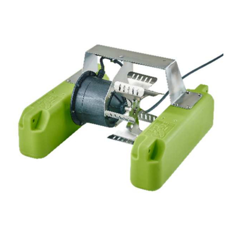
For economic packing and transport, AquaWheel is supplied in two parts (float and
complete motor housing). Assembly is very simple. Two tools are required, a 13mm
spanner, and the enclosed 30mm spanner.
a) Turn the float so that the large, single handle is at the front. Lift and rotate the
motor and cover so that the steep side of the cover faces forward. The main
paddle drive shaft will protrude from the cover from the left and right. The motor
assembly can slide on the float. Ensure that the holes in the float and motor
assembly locate in the rear position. Remove the motor cover, by loosening the
two screws at the front and rear of the cover. Remove the cover. Thread the
four 90mm screws through the holes, fit the washers, spring washers and nuts,
and tighten.
b) The impellers are enclosed loose. They only have to be fitted onto the shafts
ends. The unit with 0.55 kW has one wheel on each side, the unit with 1.1 kW
has two wheels on each side. Please note that the open sides of the blades
must always point to the front. Of course, the impellers should be mounted in the
same way. Using the 30 mm open-end wrench, you must tighten the nuts on the
impellers and thus fasten the impellers to the shaft. The unit is now fully
assembled and can be put into operation.
c) The 1.1 kW unit also contains a distance piece at the rear around the U-float.
This part must not be removed.
First Use
a) Two ropes will be needed to secure the AquaWheel in position. It is convenient
to fasten the middle of each of the two ropes to one of the holes at each front
corner of the float. Otherwise, use the handles if more convenient, ensuring that
the ropes or cable will not foul the rotating paddles when in use.
Float the aerator into position, and fasten the ends of each rope
(four fastening points) to form two “V”s. The anchors should be
at the water surface level.
Arrange the electrical supply cable carefully to prevent damage.
b) Check the direction of rotation. The direction of rotation can be changed by
swapping the wires at the live poles of the motor protection plug.
c) Do not damage the cable!
Maintenance
The AquaWheel is almost maintenance-free. The gear belt should be checked
periodically. To do this, loosen the two screws at the front and rear side of the motor
housing and remove the cover, then check the belt.
This manual suits for next models
2
Table of contents
Languages:
Other Linn Lawn And Garden Equipment manuals
