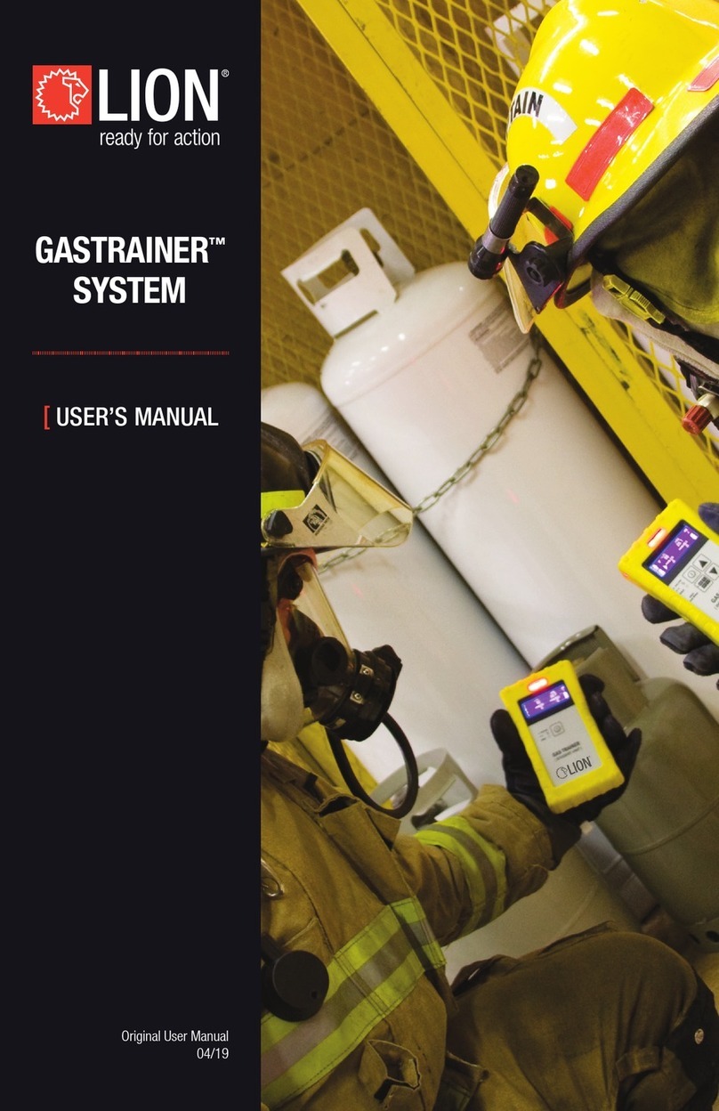
LION M-FIRE User manual

Version 1.2
14/01/20
[
USER’S MANUAL
|||||||||||||||||||||||||||||||||||||||||||||||||||||||||||||||||||||||||||||||||||||||||||
M-FIRE ‘UNITS’
ORIGINAL
USER’S MANUAL

M-Fire Units
User’s Manual
Version 1.2 | 14/01/20
Page 2
System description
General
“M-Fire” is equipment designed to allow training and practice in extinguishing various types of small fires. A
number of separate burner units are available in addition to the standard burner unit with various fire options
and accompanying attachments, so that several practical situations can be simulated in a realistic manner.
The Mobifit and M-Fire units are therefore particularly suitable for the training of in-house emergency and
first-aid officers etc.
Water, CO2 and foam can be used as extinguishing agents. Powder should not be used as an extinguisher.
The use of powder extinguishing agents results in excessive corrosion, reducing the usable life and
necessitating a lot of extra maintenance and cleaning.
The standard M-Fire operation console has wheels and handles to aid transportation. When used in a
practice building or another project-based construction, it is sometimes possible to integrate the controls
instead of using the standard console.
The M-Fire burner units are intended for installation in fixed locations.
If this is in an enclosed space, you must take the necessary precautionary measures as described in
section 2.
Construction of system
The burner unit consists of a stainless-steel housing containing two burners for the purposes of
simulating realistic fires for the unit concerned. The burners can be used individually or in combination.
M-Fire Bed
Burner 1 = pillow, Burner 2 = bedside table
M-Fire Desk
Burner 1 = desktop, Burner 2 = drawer
M-Fire Lab
Burner 1 = surface fire, Burner 2 = pointed flame (on the left-
hand side at the back)
A gas valve is placed at the bottom right of the M-Fire to close
off the gas supply.

M-Fire Units
User’s Manual
Version 1.2 | 14/01/20
Page 3
M-Fire Stove
Burner 1 = bottom (cooker), Burner 2 = top (cooker hood)
The second button from the left serves as a switch to close off
the gas supply to the cooker.
A gas valve is placed at the bottom of the M-Fire Stove to close
off the gas supply to the cooker.
M-Fire Rack
Burner 1 = lower shelf, Burner 2 = upper shelf
The burner unit is connected to the operation console via cable and gas hose. Control buttons, main
voltage indicators, and, power supply etc. are located on the control console. The standard operation
console can be used in locations without a mains power supply as it is equipped with a battery.
Safety aspects
The control desk contains an emergency stop switch. If this switch is pressed, the electrical supply
(mains voltage and low-voltage supply) will be interrupted.
The burner unit of the “M-Fire” operates on a safe voltage of 12 Volts DC.
The control console is equipped with a ball valve with which the gas supply can be interrupted. After
completing the training, the tap on the gas bottle must be closed! If the burner unit is part of a training
system, a main gas valve is provided.
The burner unit is water-resistant. The operation console is splashproof.

M-Fire Units
User’s Manual
Version 1.2 | 14/01/20
Page 4
Use of the ‘M-Fire Unit’
Connection and preparing for use
[The information below applies only to a set-up with a separate operation console]
Connect the gas hose and the cable from the operation console to the burner unit.
Next, turn on the gas valve and check that there are no leaks.
If there is a mains power supply available, you can connect the operation console to this. If there is no
mains power supply, the M-Fire console will operate on the built-in battery. This must of course be
charged.
Pull out the emergency stop switch and switch on the “power” switch.
The system is now ready for use.
When using the M-Fire Unit within a confined space, the following requirements must be met:
•The distance between the unit, the walls and the ceiling must be 3 metres or more. The walls and
ceiling must be made of non-inflammable material and must be able to withstand high
temperatures. The volume of the confined space must be at least 150 m3.
•Sufficient ventilation must be provided to a) ensure oxygen supply for combustion, and, b)
prevent the formation of inflammable and explosive mix by residual gases. Since propane gas is
heavier than air, any residual gas will sink to floor level. Therefore, there must be ventilation
along the floor surface!
•Alternatively: The area should be especially designed for fire simulations.
Operation
The operation of M-Fire Unit can be carried out in 2 different ways. By means of the selector switch,
“hand” or “auto” can be chosen.
“Hand” (manual)
The instructor determines the operation by holding down the start button.
The “M-Fire Unit” will ignite automatically by means of an electrical ignition.
Acoustic signal prior to the start: 4 beeps of approx. 0.3 seconds with the same length of time in between.
Next, the fire will ignite as determined by the selector switch:
A: Burner 1 B: Burner 1 + 2 C: Burner 2
Ignition starts simultaneously with the gas supply.
Once the fire has been put out (detected by the sensors, or, by releasing the
Once the fire has been extinguished (detected by sensors or by releasing start button), the gas supply shuts
off and an acoustic sound will be produced (a long beep of approx. 1.5 seconds). After a waiting time of
approx. 5 seconds, the unit will be ready for use.
The gas supply will be shut off and the Fail LED will flash if the unit has not ignited after 10 seconds.
After a waiting time of approx. 5 seconds, the unit will be ready for use.
“Auto” (automatic)
The operation will be started by the instructor by pressing the start button. An acoustic sound signal will
be produced while the start button is being pressed: 4 beeps of approx. 0.3 seconds with approx. 0.3
seconds gap in between. After this sound signal, the start button should be released, whereupon
the M-Fire Unit will ignite automatically and will run the chosen programme cycle (A-B-C on the selector
switch). The gas supply will be shut off and the Fail LED will flash if the unit has not ignited after 10
seconds.

M-Fire Units
User’s Manual
Version 1.2 | 14/01/20
Page 5
A: Reignition of burner 1 (lower):
Maximum duration: 60 seconds.
If extinguishing is detected (i.e. 5 seconds without fire) an acoustic signal will be produced (one single
beep). After extinguishing has been detected three times, the gas supply and the ignition mechanism will
be shut off and an acoustic signal will be produced (a long beep lasting approx. 1.5 seconds).
After a waiting time of approx. 5 seconds, the unit will be ready for use.
B: Increasing fire:
Maximum duration: 40 seconds.
The unit starts with Burner 1 (lower). After 20 seconds, seat of fire 2 (upper) ignites as well. When
extinguishing has been detected (by sensors, or, by releasing the start button) the gas supply shuts off
and an acoustic signal will be sound (a long beep of approx. 1.5 seconds). After a waiting time of approx.
5 seconds, the unit will be ready for use.
C: Reignition of seat of fire 2 (upper):
Maximum duration: 60 seconds.
If extinguishing is detected (i.e. 5 seconds without fire) an acoustic signal will be produced (one single
beep). After extinguishing has been detected three times, the gas supply and the ignition mechanism will
be shut off and an acoustic signal will be produced (a long beep lasting approx. 1.5 seconds). After a
waiting time of approx. 5 seconds, the unit will be ready for use.
Note: In the “auto” position, the cycle can be stopped by pressing the start button.
Once the fire has been extinguished (detected by sensors or by releasing start button), the gas supply shuts
off and an acoustic sound will be produced (a long beep of approx. 1.5 seconds). This single, long beep is
the “safe” signal.
In case of an emergency, the system can be shut down by pushing the emergency stop switch, switching
off the “power” switch or shutting off the gas valve (spherical plug).
Always close the gas valve on the gas cylinder after use.
Transport
The M-Fire control console must be disconnected from the “M-Fire Unit” prior to transportation. The
cables and gas hose are fixed to the console and must be rolled up around appropriate brackets. Make
sure that the gas cylinder valve is closed. The gas cylinder should preferably be transported separately.
The control console is equipped with handles and wheels to facilitate transport.
If the “M-Fire Unit” is built into a vehicle, the general instructions for that vehicle must be followed.
Maintenance
The housing of the “M-Fire Unit” is made of stainless steel, copper and / or brass.
The following measures must be taken into account:
•Handle with care.
•To ensure safety, clean the burner unit with water and non-aggressive household cleaning
products after every use.
•Regularly clean the flame detection sensors (if necessary during practice sessions) in order to
guarantee proper operation.
•Regularly check the gas pipe to prevent any clogging. Keep the openings clean and free of
contamination at all times.
•Do not leave any iron parts in the burner unit as this could pose a risk of corrosion of the stainless
steel.
It is recommended to periodically carry out an overall inspection by the supplier.
M-Fire Units
User’s Manual
Version 1.2 | 14/01/20
Page 6
The standard M-Fire console requires no special maintenance. However, the battery should be kept
charged. If the battery is empty, it should be recharged immediately by connecting the control panel to
the mains electricity and pulling out the emergency stop switch. The console may remain connected to
the mains once the battery is fully recharged.
Resolving faults
Check the gas hoses condition before each use. If leaks are detected, immediately turn off the gas
supply and ensure that repairs are carried out.
An internal fault in the electronics is indicated by the rapid blinking of the 'Fail' LED for as long as this fault
is unresolved. Operation is not possible!
In cases of overheating in the flame detection sensors, the 'Fail' LED will flash until the temperature has
returned to normal. Operation is not possible!
If the start button is pressed during the occurrence of an error, an acoustic signal will be sound (fast
beeping) for as long as the button is pushed in.
In cases of overheating, a waiting period is activated until the system releases itself.
If further errors occur, contact LION.
If the mains electricity cable of the standard M-Fire console is to be repaired or replaced, use a 3-core
rubber flex with a core diameter of 1 mm2and the specification H07RN-F.
Guarantee
•LION will replace any part of the “M-Fire Unit” in case the malfunctioning is a result of a material or
construction fault, within 12 months after the original purchase date.
•LION will not take any responsibility for any damage caused by using or defects concerning the “M-
Fire Unit.”
•In case of defects or damages, in which has been established that the operating and maintenance
instructions have not been followed, or, as a result of rough and / or unjustified handling, any claim
regarding to LION will be denied.
•The warranty will be invalid when using powder extinguishing agents.

M-Fire Units
User’s Manual
Version 1.2 | 14/01/20
Page 7
Specifications
Gas
Type of gas: gaseous propane
Gas cylinders: standard 10.5kg Shell cylinder, (diameter 30-31 cm) cylinder or similar
Pressure reducer: 0.5 / 1.5 bar max. 2kg/h
Service pressure: approx. 1 bar
Power: max. approx. 100kW
Consumption: max. approx. 7.7 kg/h
Electrical
The controls operate on 12V DC. This is supplied by the built-in power supply in the operation console /
control box. With a standard M-Fire operation console, power is also supplied by the built-in battery.
Power supply: 230V +/- 10%
Fuse 230V: 0.5 A-T
Consumed power: max. 75VA
M-Fire Console:
Operation on battery power: at least 12 hours with a fully charged battery
Fuse for “option” 1A-T
Standard M-Fire console
Operation console upon which the gas cylinder is placed.
Dimensions (width x depth x height): 40.5 x 47 x 103 cm
Weight (excluding gas cylinder): 33 kg
Connection cable for mains power: 4 m rubber flex (3g1 HO7RN)
Gas hose to combustion tank: 7.5 m
Connection flex to combustion tank: 7.5 m
Connection flex for remote control 7.5 m (optional operation of start button)
Burner units
M-Fire Bed
material: stainless steel
Dimensions (height x width x depth): 110 x 96 x 143 cm + bedside table 70 x 44 x 56 cm.
M-Fire Desk
material: stainless steel
Dimensions (height x width x depth): 80 x 120 x 70 cm + open drawer 26 cm deep.
M-Fire Lab
material: stainless steel
Dimensions (height x width x depth): 220 x 140 x 65 cm.
M-Fire Stove
material: stainless steel
Dimensions (height x width x depth): 210 x 60 x 70 cm.
M-Fire Rack
material: stainless steel
Dimensions (height x width x depth): 155 x 141 x 42 cm.

M-Fire Units
User’s Manual
Version 1.2 | 14/01/20
Page 8
Important remarks
Check for leaks in the gas hoses before each use. If leaks are detected, immediately turn off the gas
supply and ensure that repairs are carried out.
Parts of the “M-Fire Unit” can become very hot during use.
After use, check whether the “M-Fire Unit” system has cooled sufficiently before touching it.
When extinguishing using CO2, allow sufficient time between extinguishing and reignition to ensure that
no CO2 is left in or near the burner unit. The presence of CO2 hinders ignition and flame detection.
Close the gas valve on the gas cylinder after every use.
The standard M-Fire control console must be disconnected from the burner unit before transport. The
gas bottle should preferably be transported separately.
The “M-Fire Unit” may only be opened and repaired by professionally-trained personnel.
Connect the system to a properly earthed mains connection in accordance with current regulations. The
connection must be accessible at all times.
Regularly clean the M-Fire to ensure reliable operation. This is particularly necessary if powder
extinguishing agents are used to ensure reliable operation. LION advises against the use of powder
extinguishers. The warranty will not be valid if powder extinguishing agents are used.

M-Fire Units
User’s Manual
Version 1.2 | 14/01/20
Page 9
||||||||||||||||||||||||||||||||||||||||||||||||||||||||||||||||||||||||||||||||||||||||||||||||||||||||||||||||||||||||||||||||||||||||||||||||||||||||||||||||||||||||||||||||||||||||||||||||||||||||||||||||||||||||||||||||||||||||||||||||||||||||||||||||||||||||||||||
Version 1.2
14/01/20
LION Protects B.V.
Industrieweg 5
5111 ND Baarle-Nassau
the Netherlands
T: +31 (0)13 507 6800
F: +31 (0)13 507 6808
WWW.LIONPROTECTS.COM
© LION Group, Inc. All rights reserved.
Other manuals for M-FIRE
1
Table of contents
Other LION Educational Equipment manuals
Popular Educational Equipment manuals by other brands

Makeblock
Makeblock Codey Rocky & Neuron manual

MadLab
MadLab Funky Guitar quick start guide

Enabling Devices
Enabling Devices Rocking Two Message Say It Play It user guide

Buki
Buki 3700802102830 manual

LEGO
LEGO MINDSTORMS Education EV3 MicroPython Getting started

FCMP OUTDOOR
FCMP OUTDOOR Hotfrog Living Composter instructions

Copernicus
Copernicus Royal Reading Writing Center Assembly guide

TruCorp
TruCorp Trulnfant IO Leg user manual

Enabling Devices
Enabling Devices Laugh & Learn Puppy user guide

sparkfun
sparkfun KIT-10723 Information & Instructions

FireWare
FireWare Mini-Silkflame user manual

Tensegri-Teach
Tensegri-Teach Octahedron Assembly instructions