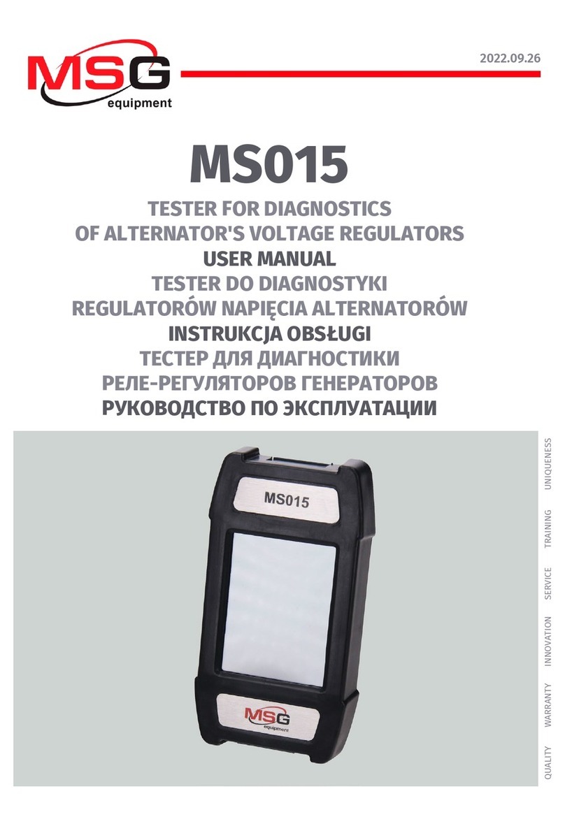
MSG Equipment MS016 User manual

2022.09.26
MS016
TESTER FOR DIAGNOSTICS OF ALTERNATOR'S
VOLTAGE REGULATORS
USER MANUAL
TESTER DO DIAGNOSTYKI REGULATORÓW NAPIĘCIA
ALTERNATORÓW
INSTRUKCJA OBSŁUGI
ТЕСТЕР ДЛЯ ДИАГНОСТИКИ РЕЛЕ-РЕГУЛЯТОРОВ
ГЕНЕРАТОРОВ
РУКОВОДСТВО ПО ЭКСПЛУАТАЦИИ
UNIQUENESS
TRAINING
SERVICE
INNOVATION
WARRANTY
QUALITY


English
Operation manual
3
CONTENTS
INTRODUCTION....................................................................................................................................................4
1. TESTER DESCRIPTION.....................................................................................................................................5
2. TESTER MENU ................................................................................................................................................10
2.1. Test modes menu...............................................................................................................................12
3. INTENDED USAGE.......................................................................................................................................... 17
3.1. Safety regulations.............................................................................................................................. 17
4. DIAGNOSTICS OF VOLTAGE REGULATORS...............................................................................................17
4.1. Voltage regulator connection.........................................................................................................18
4.2. Diagnostics of voltage regulators of Lamp type....................................................................... 24
4.3. Diagnostics of voltage regulators of RLO, RVC, C KOREA types............................................. 24
4.4. Diagnostics of voltage regulators of C JAPAN type ...................................................................25
4.5. Diagnostics of voltage regulators of SIG, P-D types .................................................................25
4.6. Diagnostics of voltage regulators of COM 12V and 24V types ............................................... 26
5. ALTERNATOR TESTING................................................................................................................................ 26
5.1. Diagnostics of 12V alternators for Stop-Start Systems ........................................................... 28
6. FUNCTION “LIN Analyzer”.......................................................................................................................... 29
6.1. Analyzer Mode.................................................................................................................................... 30
6.2. Bomber Mode .....................................................................................................................................31
Appendix 1..........................................................................................................................................................32
CONTACTS.......................................................................................................................................................... 35
Appendix 2 ...................................................................................................................................................... 104
Appendix 3 .......................................................................................................................................................107
English
Tester MS016
4
INTRODUCTION
The actual Operation Manual contains the description of a diagnostic process. The purpose is to
assess the technical condition of alternators and voltage regulators (separately from
alternators), and to read data transmitted via a LIN bus.
WARNING! The actual instruction does not provide a description of all the diagnostic aspects.
If you lack knowledge or experience, we recommend you to take training at the equipment
manufacturing facility.
The tester purpose is as follows:
1. Assessing performance of automotive alternators with a nominal voltage of 12/24V and
stop-start alternators with a nominal voltage of 12/24V (VALEO I-StARS). The diagnosis is carried
out either on a car or on the test bench that provides its drive and a load on the alternator.
2. Assessing performance of voltage regulators separately from alternators.
3. Reading and saving data transmitted via the LIN bus of a vehicle («LIN analyzer» function).
4. Diagnosing starters directly on cars without their removal or on the test bench that provides
proper unit fixation and power supply using cable MS-33503.
WARNING! Cable MS-33503 is not included in the equipment set and can be purchased
separately.
Below are the criteria for alternator and voltage regulator performance assessment:
- stabilizing voltage;
- control lamp operation;
- FR (displayed FR signal frequency and waveform, voltage regulator feedback).
For COM voltage regulators:
- ID;
- Protocol type;
- Data exchange rate;
- LIN protocol type;
- Voltage regulator self diagnosis faults.

English
Operation manual
5
1. TESTER DESCRIPTION
The tester is a portable device, its functions controlled via the touch-screen (Fig.1).
Figure 1 - General view of the tester
In the upper part of the device, there is a terminal for connection of diagnostic cables (Fig.2).
Figure 2 – Terminal for connection of diagnostic cables
There is a USB Type-C port in the bottom part of the tester, through which the power is supplied
to the tester during the diagnostics of voltage regulators. The USB port serves as well for
connection of the tester to a computer either for software updating or for data copying (Fig.3).

English
Tester MS016
6
Figure 3 - USB port, Type-C
A diagnostic cable for voltage regulators (Fig.4) and adapter cables (Fig.5) for easy connection to
the voltage regulator output terminals are included in the tester set.
Figure 4 – Diagnostic cable for voltage regulators MS-33502
Figure 5 – Adapter cables for connection to voltage regulators

English
Operation manual
7
The diagnostic cable for voltage regulators (Fig.4) has the following color markings (Table 1):
•Red cable with a clip – B+ – voltage regulator terminal B+ (terminal 30);
•Black cable with a clip – B- – voltage regulator terminal B- (GND, terminal 31);
•Orange cable with a terminal – S(Sense pin) – through this terminal, the voltage
regulator measures the battery voltage and compares it with the alternator/voltage
regulator output voltage. This cable is connected to terminals S of the voltage regulator;
•Red cable with a terminal – IG (Ignition) – the ignition terminal (terminal 15, A, IG);
•White cable with a terminal – FR – through this terminal, the data on the voltage
regulator load are transmitted. The cable connects to FR, DFM, and M terminals of the
voltage regulator;
•Grey cable with a terminal – D+ – the terminal through which the control lamp of the
voltage regulator is connected to terminals D+, L, IL, and 61 of the voltage regulator;
•Yellow cable with a terminal – GC – for connection of the tester to the control channel
of the voltage regulator through voltage regulator terminals COM, SIG, and others;
•Green cables with clips – F1, F2 – for connection of the tester to the brushes of the voltage
regulator or their corresponding terminals: DF, F, FLD;
•Blue cables with clips – ST1, ST2 – for connection of the tester to the stator terminals of
the voltage regulator: P, S, STA, Stator.

English
Tester MS016
8
Table 1 – Color markings of cable MS-33502
Clip/Terminal
Tester output
terminal
B+
B-
S
IG
FR
D+
GC
F1, F2
ST1, ST2

English
Operation manual
9
The equipment set includes a cable for alternator diagnostics (Fig.6).
Figure 6 – Diagnostic cable for alternators MS-33501
The diagnostic cable (Fig.6) has the following color markings:
•Red clip, big – „В+” – battery positive terminal, alternator output terminal. It is used to
supply power to the tester and read the alternator output voltage;
•Black clip, big – „В-” – battery negative terminal (alternator body);
•Orange clip, small - „S” (Sense pin);
•Red clip, small – „IG” (Ignition);
•White clip, small – „FR”;
•Grey clip, small – „D+”;
•Yellow clip, small – „GC”.

English
Tester MS016
10
2. MENU TESTERA
The tester main menu (Fig. 7) contains:
Figure 7 - Tester main menu
1 – Button to enter a search menu of the voltage regulator database;
2 – Button to enable “LIN Analyzer”;
3 – Button to enter the menu for selection of the tested voltage regulator type;
4 – Button to enter the menu for selection of the tested alternator type;
5 – Tag number of the connected cable;
6 – Current power supply voltage;
7 – Power supply of the tester:
– USB,
– BATTERY.
8 – Button to enter the tester settings.

English
Operation manual
11
The tester is supplied with an integrated database of voltage regulators along with their
connection diagrams. Press to enter the database search menu (Fig.7, n.1).
Figure 8 - Database search menu
Figure 9 - Menu for selection of the tested voltage regulator type

English
Tester MS016
12
Press the button with the required type of the voltage regulator to enter the alternator/voltage
regulator test mode.
Press to return to the main menu.
2.1. Test modes menu
Upon entering the test mode for voltage regulators, the following information will appear on the
screen (Fig.10):
Figure 10 - Diagnostic screen information
1 – Preset stabilizing voltage (for controlled voltage regulators);
2 – Preset rpm (this parameter will not be displayed in alternator test mode);
3* – Button to check the SENSE terminal through which the voltage regulator measures the battery
voltage (red indication: the voltage across SENSE is lower by 0.5V-0.7V than the voltage across B+);
4 - Duty cycle of PWM signal received through FR channel (the proportion of the rotor winding
“on” time);
5 – Measured stabilizing voltage;

English
Operation manual
13
6 – Test mode nominal voltage;
7 – Voltage regulator type;
8* – Button to switch the mode of data readout through FR channel;
9* – Switch starting button;
10 - Alternator control lamp indicator (for voltage regulators that directly control the lamp).
* Color indication of the button:
red – ON;
white – OFF.
The diagnostic screen for voltage regulators of COM type displays the following information:
alternator voltage regulator
Figure 11 - Diagnostic screen for alternators/voltage regulators (12/24V) of COM type
„ID” - voltage regulator identification number. The engine control unit identifies the type of the
installed alternator by this number;
„Type” – voltage regulator type. The type codes of voltage regulators operating under LIN protocol
are as follows: A1, A2, A3, A4, B1, B2, B3, B4, C3, D1, D2, E1;
„Duty” - PWM signal duty cycle (the proportion of the rotor winding “on” time);

English
Tester MS016
14
„Version LIN” – indicator of voltage regulator protocol version (LIN1 or LIN2);
„Errors” - indicator of errors transmitted by the voltage regulator to the engine control unit. Types
of potential errors:
• E – electrical error;
• M – mechanical error;
• TH – thermal error.
„Speed” - indicator of data exchange rate under LIN protocol supported by a COM voltage
regulator. The following rate values may be displayed:
• „L” – 2400 baud (low);
• „M” – 9600 baud (medium);
• „H” – 19200 baud (high).
Figures 12-15 show the information displayed when different voltage regulator types are tested.
alternator voltage regulator
Figure 12 - Diagnostic screen for alternators/voltage regulators of RLO, RVC,
C KOREA types

English
Operation manual
15
alternator voltage regulator
Figure 13 - Diagnostic screen for alternators/voltage regulators of C JAPAN type
alternator voltage regulator
Figure 14 - Diagnostic screen for alternators/voltage regulators (12/24V) of Lamp type

English
Tester MS016
16
alternator voltage regulator
Figure 15 - Diagnostic screen for alternators/voltage regulators of SIG type
alternator voltage regulator
Figure 16 - Diagnostic screen for alternators/voltage regulators of P/D type

English
Operation manual
17
3. INTENDED USAGE
1. Use the tester as intended (see INTRODUCTION).
2. The tester is designed for indoor use. Be aware of the following operating constraints:
2.1. The tester should be used in the spaces equipped at the temperature range from +10 °С up
to +40 °С and the relative humidity range from 10 up to 75% without moisture condensation.
2.2. Do not use the tester at the low temperature and high humidity (more than 75%). When the
tester is brought from the cold place (outdoors) into the warm place, the condensate can appear
on its elements. Thus, do not turn on the tester at once. Wait for 30 minutes until switching it
on.
2.3. Keep the tester far from the direct sunlight.
2.4. Keep away from heating devices, microwaves, and other temperature-raising equipment.
2.5. Avoid dropping the tester or spilling technical liquids on it.
2.6. Any interference with the electric diagram of the device is strictly prohibited.
2.7. Make sure the crocodile clips are completely insulated before connecting them to the
alternator/voltage regulator terminals.
2.8. Avoid the crocodile clips short circuit between themselves or to any conductive parts of a
vehicle, including its body.
2.9. Do not put the tester on the vehicle battery or other elements of the underhood space.
Avoid short circuit of the tester housing to the conductive parts of a vehicle.
2.10. Do not use the device with a faulty power unit.
2.11. Turn off the tester when it is not in operation.
3. In case of failures in the operation of the tester, stop further operation and contact the
manufacturer or sales representative.
WARNING! The manufacturer is not responsible for any damage or injury to human health
resulting from non-compliance with the requirements of this user manual.
3.1. Safety regulations
The operation of the tester requires technical proficiency of the operator, he must be authorized
to operate certain types of test benches (devices) and receive safety training.
4. VOLTAGE REGULATOR TESTING
Generally, most voltage regulators are tested as follows:
1) Connection of a voltage regulator to the tester;
2) Selection of the type and nominal voltage of the tested voltage regulator;
3) Assessment of the control lamp operability: when speed is about 0 rpm, the battery indicator
must light up (red). As the speed increases up to 800-1200 rpm, the indicator must go out.
4) Assessment of the „S” terminal operability;
5) Assessment of the voltage regulator capability to adjust to the preset stabilizing voltage. Use a
cursor (Fig.10, n.1) to set the voltage.

English
Tester MS016
18
WARNING! The test mode (Fig.9) should correspond to the type of the tested voltage regulator.
Connect both cable MS-33502 and a power unit equipped with «Quick Charge 2.0» to the tester
through USB Type-C port to launch the diagnostic procedure.
WARNING! If the connected power unit doesn’t feature «Quick Charge 2.0», the tester can test
12V voltage regulators only.
WARNING! Operationof some TM Bosch voltage regulators requires a heavy current, the tester
cannot deliver. Voltage regulators of this type cannot be tested.
4.1. Voltage regulator connection
Assessment of the voltage regulator operability requires a proper connection of the diagnostic
cable to the voltage regulator.
Use the voltage regulator OEM number to search the terminal markings against the database
(Fig.17).
Figure 17 - Voltage regulator search against the database and search results
Connect the diagnostic cable to the voltage regulator as shown on the diagram.
WARNING! To avoid damage (failure) to the voltage regulator, extra care should be taken when
connecting thecable clips to the contacts in the terminals. Use either a well-insulated clip (Fig.18)
or a proper adapter cable (Fig.5).

English
Operation manual
19
Figure 18 - Connection of cable clips to the contacts in the terminals
When the connection is made, press «OK» - the tester will automatically switch over to the test
mode appropriate for the tested voltage regulator. Then, proceed to the voltage regulator testing
(the process is described below).
If the information on the markings of the voltage regulator terminals cannot be found in the
database, research online. Appendix 3 is yet another source of information. There you can find
connection diagrams of the most common voltage regulator types. Use the diagram with terminal
markings found online and the examples below to connect the diagnostic cable.
Figure 19 shows a diagram (an example) for connection of voltage regulator ARE1054.
Figure 19 - Voltage regulator ARE1054

English
Tester MS016
20
Identify the type of the voltage regulator by the terminal contacts shown in Fig.19 and use
information set out in Appendices 1, 2 of the actual Instruction. Shown here are terminals DFM
and L(RVC) (can also be marked as L(PWM)). By terminal L (RVC) we identify this voltage regulator
as RVC type.
Then, using Appendix 1, we determine which clips (connectors) of the diagnostic cable must be
connected to the voltage regulator. A diagram of voltage regulator ARE1054 connection to the
tester is shown both in Table 2 and Figure 20.
Table 2 – Connection of voltage regulator ARE1054 to the tester
Voltage regulator
terminal
Tester output terminal
Color marking of
cable
DFM
FR
white
L(RVC)
GC
yellow
Ps
ST1
blue
B+
B+
red
DF
F1
green
F2
green
B-
B-
black
Figure 20 - Diagram of voltage regulator ARE1054 connection to the tester
Other manuals for MS016
1
Table of contents
Languages:
Other MSG Equipment Test Equipment manuals

MSG Equipment
MSG Equipment MS300 User manual

MSG Equipment
MSG Equipment MS1000+ User manual

MSG Equipment
MSG Equipment MS603N User manual

MSG Equipment
MSG Equipment MS015 User manual

MSG Equipment
MSG Equipment MS112 User manual

MSG Equipment
MSG Equipment MS021 User manual

MSG Equipment
MSG Equipment MS008 User manual

MSG Equipment
MSG Equipment MS031 User manual

MSG Equipment
MSG Equipment MS005 User manual

MSG Equipment
MSG Equipment MS002 COM User manual