manuals.online logo
Brands
  1. Home
  2. •
  3. Brands
  4. •
  5. Litepanels
  6. •
  7. Lighting Equipment
  8. •
  9. Litepanels STORM ASTRA User manual

Litepanels STORM ASTRA User manual




Lighting Sound Video
Rigging Cable & Distro Set & Stage
TECHNICAL SERVICES FOR
EVENTS, THEATRE, MUSIC,
EXHIBITION, FILM & TV
01483 757211
HIRE@STORMLTD.CO.UK
WWW.STORMLTD.CO.UK
A
M
H
J
I
M
E
M
C
B
M
G
D
K
L
FN
O
ON / OFF BUTTON
DIMMER KNOB
COLOR KNOB
POWER / STATUS INDICATOR LIGHT
3-PIN MALE XLR POWER JACK
3-PIN FEMALE XLR POWER PLUG
YOKE
YOKE KNOB (2 PLACES)
FAN MODULE (ASTRA 6X ONLY)
MODULE WELL COVER
IEC POWER RECEPTACLE
BATTERY PLATE MOUNTING HOLES
VENTS
TVMP ADAPTER
TVMP KNOB
(A)
(B)
(C)
(D)
(E)
(F)
(G)
(H)
(I)
(J)
(K)
(L)
(M)
(N)
(O)
SEE REVERSE
POWERING THE FIXTURE
Plug the Power Supply Adapter (included) into the mains using the US or EU AC Power Cord (included). The
power supply adapter is affixed to the yoke by clips and can be detached if desired.
CAUTION: The power supply adapter can get hot during use.
CAUTION: Use only the included power supply adapter.
Plug the 3-pin Female XLR Plug (“F”) from the Power Supply Adapter into the 3-Pin Male XLR Jack (“E”) on
the rear of the fixture. Insert the plug firmly and completely.
For battery use, attach a compatible Anton Bauer®V-Mount or Gold Mount battery plate to the back of the
yoke using the four 4-40 threaded Battery Plate Mounting Holes (“L”). Plug the battery plate power inlet cable
into the 3-pin male XLR jack on the rear of the fixture. (Battery, battery plate, mounting hardware, and battery
plate power inlet cable are not included.)
MOUNTING THE FIXTURE
The ASTRA fixture is attached to a Yoke (included, see “G” above) that features a TVMP Adapter (“N”). If desired, the TVMP adapter can be removed and
replaced with other standard mounting hardware (not included). Always comply with applicable local regulations, and use other safety equipment (e.g. safety chain
or cable, not included) when required.
CAUTION: When hanging the fixture or mounting it to a stand, position the yoke such that the fixture is oriented mostly right-side-up.
WARNING: Keep the fixture’s Vents (“M”) clear from obstruction. Allow more than 15 cm [6 inches] of air space between the side vents and the nearest
obstruction. Allow more than 15 cm [6 inches] of air space between the rear of the fixture and the nearest obstruction.
Use only accessories made or approved by the manufacturer, and ensure that accessories do not obstruct the vents.
Do not operate the ASTRA fixture in an environment other than as specified by the following: ambient temperature between -20°C and 45°C [between -4°F and
113°F]; less than 85% relative humidity (RH), no condensation.
INCLUDED
ASTRA 3X or ASTRA 6X Bi-Color LED Fixture
Yoke w/ Power Supply Adapter
AC Power Cord, US (not pictured)
AC Power Cord, EU (not pictured)
SAFETY INFORMATION
To clean the ASTRA, wipe with a clean, dry cloth.
Do not restrict air flow around the ASTRA. Keep the fixture’s vents clear of obstruction.
Plug the ASTRA into a mains electrical receptacle using only the included Power Supply Adapter.
Use a mains electrical receptable rated 100/120V 220/240V 50/60Hz only.
Use the US AC Power Cord only with a grounded, polarized 3-pin power receptacle (Type B).
Do not use, mount, transport, or store the ASTRA near radiators, space heaters, ovens, stoves, heat registers, open flame, or any heat source.
Do not use, mount, transport, or store the fixture in an environment with an ambient temperature greater than 65°C [149° F].
Protect the power cables of the ASTRA from pinching, twisting, or crushing.
Unless otherwise herein specified, the ASTRA contains no user-servicable parts. Tampering with or disassembling the fixture will void the manufacturer’s warranty.
WARNING: To reduce the risk of electric shock or fire, do not expose the ASTRA to rain, moisture, or liquids.
Immediately consult with qualified Litepanels®service personnel when any of the following have occurred: The fixture has been dropped or impacted; the power
cables have been damaged; the fixture has been exposed to rain, moisture, or liquid; the fixture does not operate normally.
This device complies with Part 15 of the FCC Rules. Operation is subject to the following two conditions: (1) this device may not cause
harmful interference, and (2) this device must accept any interference received, including interference that may cause undesired operation.
STUDIO LIGHT FLOOD BI-COLOR LED FIXTURE (935-2023 / 935-1023)
/BI-COLOR
1 2
3
PIN 1 = GRND
PIN 2 = +V
PIN 3 = Not Connected
PINOUT DIAGRAM (3-PIN MALE XLR JACK)
www.litepanels.com
OPERATION
To power on, depress the On/Off Button (see “A” above) until it latches, then release. To power off, depress the On/Off Button again to unlatch.
The Power/Status Indicator Light (“D”) is green to indicate that the fixture is powered and operating normally. The Power/Status Indicator light will turn red or flash red
to indicate a warning or a fault condition. See “TROUBLESHOOTING” below for more information.
The ASTRA features 0 – 100% dimmer control. To increase brightness, turn the Dimmer Knob (“B”) clockwise. To decrease brightness, turn the Dimmer Knob
counterclockwise. RECOMMENDED: When turning the light off for a short time (less than 90 minutes), turn the dimmer down to zero rather than turn the power off
using the On/Off Button.
Turn the Color Knob (“C”) to change the color of the light output. Turn the Color Knob clockwise for more daylight (cool white) color. Turn the Color Knob
counterclockwise for more tungsten (warm white) color.
When the fixture is operated remotely via a valid communication signal (e.g. DMX 512), the Dimmer Knob and Color Knob are temporarily disabled. When the remote
signal is discontinued, the dimmer and color values hold at their most recently transmitted levels. Control is then returned to the Dimmer and Color Knobs when either
are adjusted manually.
REMOVING THE MODULE WELL COVER
To install the optional modules (not included) or access the fan switch, the Module Well Cover
(see “J” above) must be removed. To remove the module well cover, squeeze the right and left
latches toward each other and lift.
To replace the module well cover, insert its two hooks into their corresponding slots and swing
into place. Push down until the latches snap into place.
OPTIONAL MODULES
(not included)
DMX Communications Module with RJ45 Ports (900-3501)
DMX Communications Module with 5-pin XLR Ports (900-3502)
Bluetooth®Communications Module (900-3519)
DISABLING / ENABLING THE FAN (ASTRA 6X ONLY)
The ASTRA 6X uses active fan cooling to maximize its brightness output. The fan can be disabled if
desired. Disabling the fan will reduce the fixture’s maximum brightness output by 50%.
To disable or enable the Fan, adjust the Fan Switch (“P”). To access the fan switch, the module well
cover must be removed (see “REMOVING THE MODULE WELL COVER” below).
Refer to the Serial Label (“Q”) for guidance. To enable the fan, push the switch upward to ON (AUTO).
The fan speed will automatically adjust to optimally regulate the fixture’s temperature. To disable the
fan, push the switch downward to OFF. Replace the module well cover.
In the unlikely event of fan failure, the Fan Module (“I”) is a user-serviceable part that can be replaced.
See litepanels.com/support for details.
The ASTRA 3X is not equipped with a fan.
Vitec Production Solutions Limited
www.vitecgroup.com
Register your product online at www.litepanels.com
I
P
Q
LATCH
LATCH
HOOK
HOOK
red flash, pause,
(repeat)
red solid on
red flashes (2X), pause,
(repeat)
red flashes (4X), pause,
(repeat)
red flashes (other)
red flash, pause,
red flashes (3X), pause,
(repeat)
Note the red flashes pattern and contact
service at litepanels.com/support
Fixture is operating normally.green solid on
TROUBLESHOOTING
There is no light output.
Light turns off.
Adjust dimmer knob to change brightness.
Turn the dimmer down to 0% and allow
fixture to cool. Check fan and vents.
Turn the dimmer down to 0% and allow
fixture to cool. Check fan and vents.
Check the fan for blockage. Replace fan
module if necessary.
Change power source.
Turn fixture off; change power source.
Condition
Power/Status Indicator
Behavior Recommended Action
Input Over Voltage Fault
green flashesPower/Status Indicator flashes
green when fixture is powered on.
Take no action. The green flashing stops
shortly after the fixture has been powered on.
Fixture is operating normally.
red solid onLight turns off.
Light turns off.
Input Under Voltage Fault
Input Under Voltage Warning
The light is not operating
normally.
Light brightness
decreases by 50%.
Light is on.
Light is on.
Over Temperature Fault
Over Temperature Warning
Fan is malfunctioning.
Fixture is malfunctioning.

Other Litepanels Lighting Equipment manuals

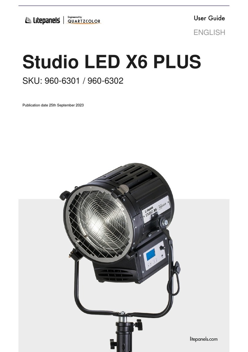
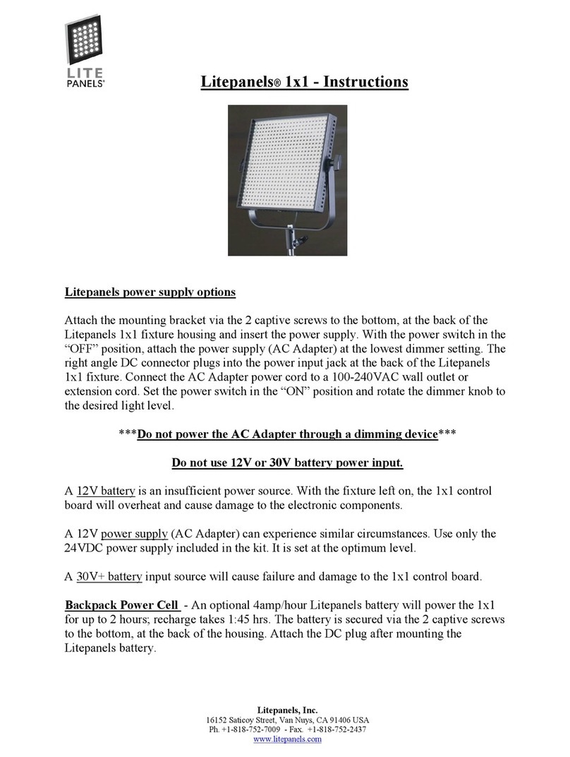
Litepanels Gemini 1x1 Soft User manual

Litepanels

Litepanels Gemini 1x1 Soft User manual

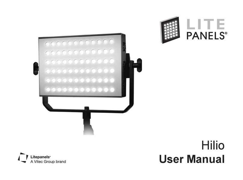
Litepanels Hilio User manual

Litepanels

Litepanels Hilio User manual

Litepanels Gemini 1x1 Soft User manual

Litepanels

Litepanels Gemini 1x1 Soft User manual

Litepanels Studio LED X3 PLUS Bicolor User manual

Litepanels

Litepanels Studio LED X3 PLUS Bicolor User manual

Litepanels Gemini 1x1 Soft User manual

Litepanels

Litepanels Gemini 1x1 Soft User manual

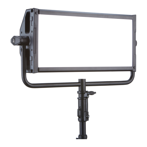
Litepanels GEMINI 2X1 HARD Series User manual

Litepanels

Litepanels GEMINI 2X1 HARD Series User manual

Litepanels Ringlite Mini User manual

Litepanels

Litepanels Ringlite Mini User manual

Litepanels Studio LED X6 PLUS User manual

Litepanels

Litepanels Studio LED X6 PLUS User manual

Litepanels Gemini 2x1 Soft User manual

Litepanels

Litepanels Gemini 2x1 Soft User manual

Popular Lighting Equipment manuals by other brands

Lumatek LUMLED012 manual

Lumatek

Lumatek LUMLED012 manual

BEARWARE 303586 manual

BEARWARE

BEARWARE 303586 manual

GE 19005LO quick start guide

GE

GE 19005LO quick start guide

Cameo TRIBAR 400 IR user manual

Cameo

Cameo TRIBAR 400 IR user manual

Loevschall F15-350 Instructions for use

Loevschall

Loevschall F15-350 Instructions for use

Fomei FY3566 manual

Fomei

Fomei FY3566 manual

Pentair SOLEO CL Installation and user guide

Pentair

Pentair SOLEO CL Installation and user guide

EuroLite CPE-40 user manual

EuroLite

EuroLite CPE-40 user manual

Knightsbridge CPL6CT Installation & maintenance manual

Knightsbridge

Knightsbridge CPL6CT Installation & maintenance manual

Awex ARROW P Assembly instructions

Awex

Awex ARROW P Assembly instructions

Drobo 5C user guide

Drobo

Drobo 5C user guide

Event Lighting PIXBAR12x3 user manual

Event Lighting

Event Lighting PIXBAR12x3 user manual

EuroLite PSL-500 user manual

EuroLite

EuroLite PSL-500 user manual

Home Accents Holiday TY094-1614-1 Use and care guide

Home Accents Holiday

Home Accents Holiday TY094-1614-1 Use and care guide

Springtree HD202 WW user manual

Springtree

Springtree HD202 WW user manual

elvita E115644 user manual

elvita

elvita E115644 user manual

ADJ COB CANNON WASH User instructions

ADJ

ADJ COB CANNON WASH User instructions

Larson Electronics IND-LLP-UVC-KT.EV-R1-120V-0.75IN instruction manual

Larson Electronics

Larson Electronics IND-LLP-UVC-KT.EV-R1-120V-0.75IN instruction manual

manuals.online logo
manuals.online logoBrands
  • About & Mission
  • Contact us
  • Privacy Policy
  • Terms and Conditions

Copyright 2025 Manuals.Online. All Rights Reserved.