LOBSTER AR 2000H User manual

AIR RIVETER
INSTRUCTION MANUAL
AR 2000S(A)
AR 2000 (A)
AR 2000H(A)
Professional model of air riveter to install blind rivets.
¡Thank you very much for purchasing “LOBSTER” air riveter. To ensure correct operation, please
read this instruction manual carefully, and keep it in a safe place for later reference.
¡This instruction manual contains information for models AR2000S(A), AR2000M(A) and AR2000H(A).
Be sure to refer to information that is applicable to the model you are using.
¡
This is Original instructions. (Original Instruction Manual is written in English language.)
CONTENTS
I PORTANT SAFETY
INSTRUCTIONS.................................1
NO ENCLATURE .............................5
TECHNICAL DATA ............................6
PREPARATION BEFORE USE .........7
OPERATING THE AIR RIVETER ......8
AINTENANCE.................................9
STORAGE........................................14
TROUBLESHOOTING.....................15
AR2000S(A) PARTS TABLE ............17
AR2000 (A) PARTS TABLE ............19
AR2000H(A) PARTS TABLE ............21
International Marketing & Sales Division
12-8 Shijyo-cho, Higashi-Osaka City
Osaka 579-8053, Japan
Te ephone: +81(72)981-7466 Te efacs: +81(72)981-9420
URL http://www. obtex.co.jp/
MANUFACTURER
PRINTED IN APAN
英語/ENGLISH
AR-2000S-M-H(A)取扱(GB):AR-2000SM-H(A)取扱(GB)14/08/2713:55ページ1

1
英語/ENGLISH
IMPORTANT SAFETY INSTRUCTIONS
◆Be sure to read the following Important Safety Instructions carefully and make sure that you
understand them thoroughly before using this tool.
◆Always wear eye-protection at all times during use. If this is not observed, the cut mandrels
may eject out when the rivets are cut and cause serious injury.
: Indicates a potentially hazardous situation which, if not avoided, could result in death or
serious injury to the operator.
: Indicates a potentially hazardous situation which, if not avoided, may result in moderate
injury to the operator or physical damage.
Moreover, failure to follow the instructions marked with the symbol or cautions without a
symbol which appear in the text of this manual may also have serious results in some cases.
Always be sure to observe the instructions given in the Important Safety Instructions.
tCAUTION
tCAUTION
tCAUTION
tWARNING
1.
The air pressure should be kept within the range of 0.49 to 0.59 Pa (5 to 6 kgf/cm
2
, 71 to 85 psi).
¡If an air pressure which is greater than this is used, the tool may become damaged, and injury or
damage to property may result.
2.
Always attach the safety cap before use.
¡
If this is not observed, the cut mandrels may eject out when the rivets are cut and cause serious injury.
3. Be sure to remove the frame head when adding hydraulic oil through the cylinder.
¡If the frame head is not removed before adding oil, excess oil may remain inside the tool, and damage to
the tool or personal injury may result. (Except the case when adding hydraulic oil through the bleed plug.)
4. ake sure that the tool and the air source are connected securely.
¡If the threads of the joints do not match or if the screws are not inserted far enough, the air hose may
become disconnected during use and injury may result.
¡Use hose bands to securely connect the air hose joint and air hose. If they are not connected securely
enough, the air hose may become disconnected during use and injury may result.
5. Turn off the air supply before disconnecting the tool from the air source.
¡Compressed air may cause the air hose to whip around, and injury may result.
6. Check that all the tool parts are free from damage before use. Any damaged parts
should be repaired before the tool is used.
¡If the tool is used while any parts are still damaged, injury may result.
¡If the hose is damaged by objects being dropped onto it, for instance, the damaged part may rupture
and accident or injury may result.
¡Don't pull and drag the tool by the air hose. It may trigger some damages on the tool body, breakage of
Rotary oint or some other defects and lead serious troubles with injuries.
◆After reading this manual, keep it in a safe place where it is easily accessible to tool users.
tWARNING
◆This is the safety alert symbol. It is used to alert you to potential personal injury hazards.
Obey all safety messages that follow this symbol to avoid possible injury or death.
◆The Important Safety Instructions are divided into and .
The differences between these two levels are described below.
tCAUTION
tWARNING
AR-2000S-M-H(A)取扱(GB):AR-2000SM-H(A)取扱(GB)14/08/2713:55ページ1

2
英語/ENGLISH
7. If using in elevated locations, use a safety harness, and take care to avoid dropping
rivets or the tool itself.
¡Accident or injury may result if this practice is not followed.
8 Never look into the nosepiece of the tool, and never point the nosepiece toward other
persons.
¡If the tool is used while the cut mandrels are still inside the tool not being ejected, these mandrels may
be ejected from the tool's nosepiece during use and cause serious injury.
9 Wear protective glasses during use.
¡Failure to do so may result in an accident or personal injury in case that a rivet or a piece of cut
mandrels jumps out toward you.
tWARNING
AR-2000S-M-H(A)取扱(GB):AR-2000SM-H(A)取扱(GB)14/08/2713:55ページ2

3
英語/ENGLISH
1. Always turn off the air supply before disassembling the tool for cleaning and
maintenance purposes.
¡If the tool is cleaned or disassembled with the air supply connected, injury may result.
2. Do not use the tool with the frame head removed.
¡Items such as fingers may become caught in the mechanism.
3. Do not bring your face close to the air outlet holes.
¡Pressurized air containing fine particles is discharged from the air outlet holes during use. Keep eyes
away from this area.
4. Avoid skin contact with substances such as hydraulic oil, lubricating oil and grease.
¡Such substances may cause inflammation of the skin. If they come into contact with your skin, wash
the affected area thoroughly.
5. ake sure that the workplace is safe, clean and organized.
¡Accidents can easily occur in untidy workplaces.
¡If the cut mandrels are allowed to fall onto the floor, you may slip on them, and injury may result.
6. Avoid uncomfortable postures while working.
¡You may fall down and injury may result.
7. Keep people who are not involved in work away from the workplace.
¡Accidents or injury may result.
8. aintain the tool with due care.
¡Refer to the Instruction Manual for details on replacing parts and attachments, otherwise injury may occur.
¡Keep the grip clean and dry at all times, and never let it become greasy, otherwise injury may occur
during use.
9. Use the tool carefully and concentrate on correct operation at all times.
¡Use the tool with proper care, paying full attention to methods of handling and operation and
surrounding conditions. Accidents and injury may result if this practice is not followed.
¡Use common sense at all times, otherwise accidents or injury may result.
¡When you are tired, do not use the tool, otherwise accidents or injury may result.
10. Ask Lobtex to carry out any repair work required.
¡Repair work should only be carried out by a qualified technician. Please contact your nearest
“LOBSTER” distributor, representative, or direct to Lobtex Co., Ltd., Osaka. If the tool is repaired by
someone without the necessary qualifications and experience, the tool may not perform to optimum
standards, and accidents or injury may result.
11. Do not attempt to modify the tool.
¡Unauthorized modifications may cause malfunctions which can lead to accidents or injury.
12. Only for EU countries, do not dispose of electric tools together with household waste
material !
¡In observance of European Directive 2002/96/EC on waste electrical and electronic equipment and
its implementation in accordance with national law, electric tools that have reached the end of their
life must be collected separately and returned to an environmentally compatible recycling facility.
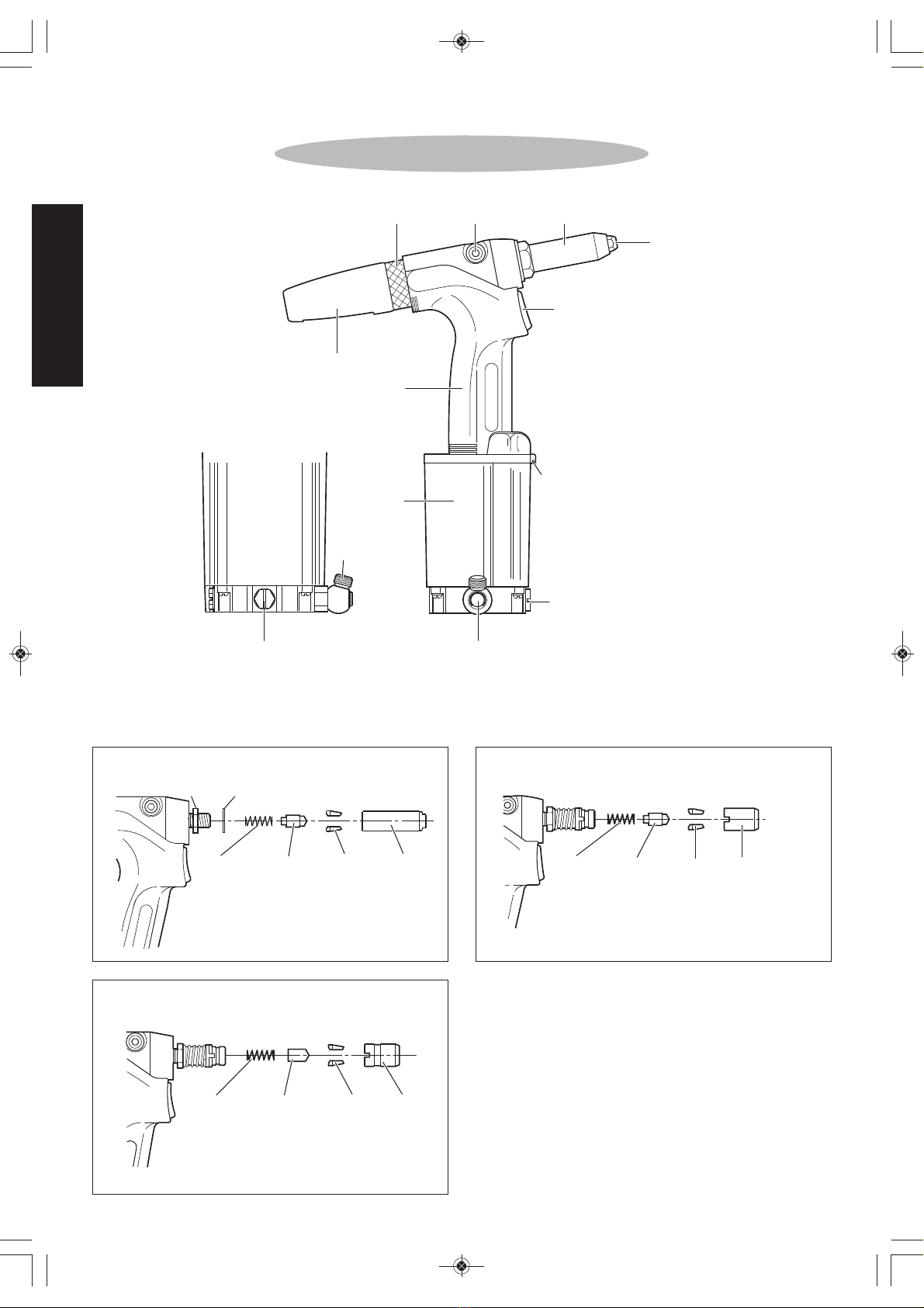
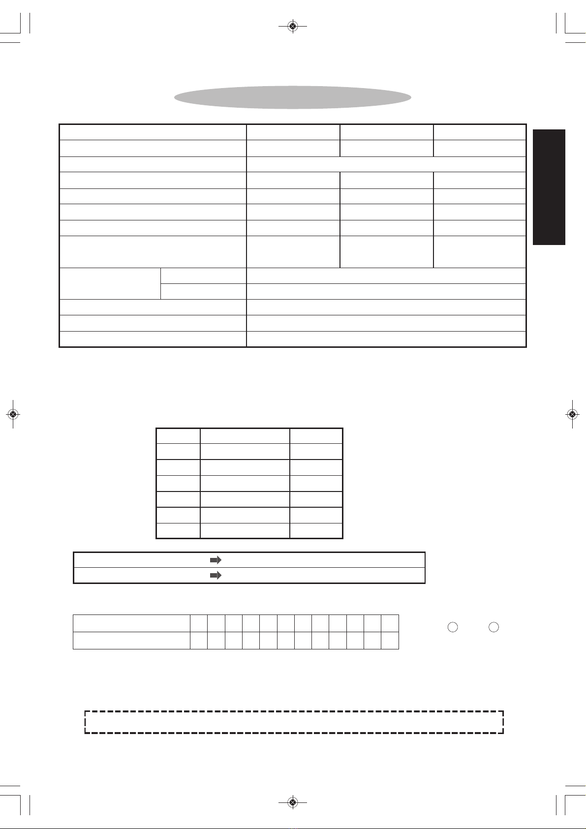
13. The parts to be used must be those supplied from us or recommended by us.
Select and attach parts applicable to your rivet.
¡Otherwise the unit may not produce maximum performance and may sometimes malfunction
resulting in an accident or personal injury.
14. Do not leave the floor littered with cut-mandrels.
¡Cut-mandrels are dangerous because their ends are sharp. Stepping on them is also dangerous
easily causing a slip and fall accident.
tCAUTION
AR-2000S-M-H(A)取扱(GB):AR-2000SM-H(A)取扱(GB)14/08/2713:55ページ3

4
英語/ENGLISH
15. The production date of this product is shown brevity code below the tools. (on page6)
16. Important information and clue about the use are listed in main body label. When
contents cannot read by contamination or by the damage of the label, please order a
new label and put it.
The new label could be ordered from us (Lobtex) via distributor.
17. This product is a tool for exclusive use of the professional business. When you are the
one who uses this tools for the first time, please receive an instruction from the one
who have already used this tools before, also please read the Instruction anual
carefully and understand the content.
¡Wear protective goggles or safety glasses.
¡When this product is damaged, please do not use.
18. For the maintenance of the main body, for every 30,000 installation of the fastener or in
one year.
19. Only qualified and trained operators should install, adjust or use the assembly power
tool for non-threaded mechanical fasteners.
20. Do not modify this assembly power tool. odifications can reduce the effectiveness of
safety measures and increase the risks to the operator.
21. Slips, trips and falls are major causes of workplace injury. Be aware of slippery
surfaces caused by use of the tool and also of trip hazards caused by the air line or
hydraulic hose.
22. Proceed with care in unfamiliar surroundings. There can be hidden hazards, such as
electricity or other utility lines.
23. This assembly power tool is not intended for use in potentially explosive atmospheres
and is not insulated against contact with electric power.
24. Ensure that there are no electrical cables, gas pipes, etc., which can cause a hazard if
damaged by use of the tool.
25. If you experience numbness, tingling, pain or whitening of the skin in your fingers or
hands, stop using the assembly power tool, tell your employer and consult a
physician.
26. Air under pressure can cause severe injury:
¡always shut off air supply, drain hose of air pressure and disconnect tool from air supply when not in
use, before changing accessories or when making repairs;
¡never direct air at yourself or anyone else.
27. Whipping hoses can cause severe injury. Always check for damaged or loose hoses
and fittings.
28. Never carry an air tool by the hose.
29. The regular preventative maintenance shall be carried out, for instance after a
specified time of operation, a specified number of cycles/operations or a stated
number of times per year.
30. When disposing this tool, please follow the regulations and the rules of the country
and autonomous community.
tCAUTION
AR-2000S-M-H(A)取扱(GB):AR-2000SM-H(A)取扱(GB)14/08/2713:55ページ4

5
英語/ENGLISH
NOMENCLATURE
CHANGE PLUG
ROTARY JOINT UNIT
CHANGE PLUG
FRAME HEAD
NOSEPIECE
SWITCH
AIR OUTLET HOLE
SAFETY CAP
FRAME
CYLINDER
BLEED PLUGFRAME CAP
THREADS G1/4
(PF1/4)
FRAME HEAD INTERNAL PARTS
Lock washer
Jaw !
pusher !
spring
Jaw pusher Jaws ‘S’! Jaw case
Jaw case lock nut
AR2000S(A)
Jaw !
pusher !
spring ‘H’!
Jaw !
pusher ‘H’!
Jaws ‘H’! Jaw !
case !
head ‘H’!
AR2000H(A)
Jaw !
pusher !
spring!
Jaw pusher! Jaws ‘M’! Jaw case head!
AR2000 (A)
AR-2000S-M-H(A)取扱(GB):AR-2000SM-H(A)取扱(GB)14/08/2713:55ページ5

6
英語/ENGLISH
TECHNICAL DATA
odel No.
Weight kg (lbs)
Operating air pressure
Dimensions
(Length×Height×Width) mm
Air consumption per rivet r(c.ft.)
Tool stroke mm (inch)
Traction power at 0.59 Pa
kN (kgf)
AR2000S(A)
1.1 (2.43)
266×240×95
0.6 (0.021)
14 (35/64)
4.8 (489)
AR2000M(A)
1.2 (2.65)
270×283×95
1.7 (0.060)
16 (5/8)
9.1 (928)
AR2000H(A)
1.6 (3.53)
295×323×105
3.6 (0.127)
18.5 (23/32)
14.0 (1,428)
* 4.0 mm stainless steel rivets can not be used.
¡Product specifications and design are subject to change for improvement without notice.
¡Weight and dimensions given are standard values. Actual products may differ slightly from the values given.
¡AR2000H(A) is available to install 2.4 (3/32”), 3.2 (1/8”) and 4.0 (5/32”) blind rivets subject to conversion of jaw
case head, ultra jaws, jaw pusher and nosepiece.
■
Air consumption calculation m thod
■
Use the following calculation method to obtain the required air consumption, and select the compressor accordingly.
Make sure that this corresponds to the compressor discharge capacity (per minute).
Required air consumption =Air consumption per rivet ×No. of rivets per minute
Applicable rivets φmm
(rivet diameters) φinch
0.49 ~ 0.59 MPa (5 ~ 6 kgf/cm2, 71 ~ 85 psi.)
2.4, 3.2, 4.0*
3/32, 1/8, 5/32*
2.4, 3.2, 4.0, 4.8
3/32, 1/8, 5/32, 3/16
4.8, 6.4
3/16, 1/4
Index no.
3
4
6
1
1
1
Part name
aw case head ʻMʼ
Ultra jaws (pair) ʻMʼ
aw pusher ʻHʼ
Nosepiece ʻLʼ 2.4
Nosepiece ʻLʼ 3.2
Nosepiece ʻLʼ 4.0
Code no.
14378
10281
10224
10213
10214
10215
Operating environment
Temperature
Relative humidity
Sound Pressure level (Lpa)
Vibration Emission value
Air intake (Rotary joint)
4° to 35 °C
80%RH max. (no condensation)
75 dB
Less than or equal to 2.5 m/sec2
Size of screw G1/4 (PF1/4)
Manufacturing year of unit Indicated on the Cylinder top unit
Caution label Attached on the side of Air Cylinder
* Rated plate and caution plate is identical.
How to check manufactured date
1 2 3 4 5 6 7 8 9 10 11 12
A B M N K T Y U O L Z
year: 2014 month: 8 → NY
↓N↓Y
Example
A year/month of manufacture
An English character
AR-2000S-M-H(A)取扱(GB):AR-2000SM-H(A)取扱(GB)14/08/2713:55ページ6

Replace the nosepiece to conform to the size of
the rivet being used.
The rivet size indicates the diameter of the rivet.
NOTE:
¡Different-sized rivets can be used just by replacing the
nosepiece.
¡At the time of purchase, the AR2000S(A) and AR2000M(A) are fitted with a 3.2 nosepiece, and the
AR2000H(A) is fitted with a 4.8 nosepiece.
¡If you wish to use other sizes, use a spanner to remove and replace the nosepiece.
7
英語/ENGLISH
PREPARATION BEFORE USE
1
2
3
4
5
Use the air regulator to adjust the operating air pressure to 0.49 ~ 0.59 Pa
(5 ~ 6 kgf/cm2, 71 ~ 85 psi).
AIf installing stainless steel rivets with a diameter of 4.8 mm (3/16") with the AR2000M(A),
set the air pressure to 0.54 ~ 0.59 MPa (5.5 ~ 6 kgf/cm2, 78 ~ 85 psi).
tWARNING 1 (P.1)
Remove the dust-proof cap on the bottom of
the tool, and then connect the rotary joint unit.
AConnect the end of the rotary joint unit which has the
O-ring fitted to the tool.
Install the safety cap to the tool.
Set up the compressor, and be sure to install an
air filter, air regulator and air lubricator (3-device
set) between the compressor and the tool.
tWARNING 2 (P.1)
tWARNING 4 (P.1)
ATTENTION:
If the air pressure is too high, damage to parts may occur. If the pressure is too low,
some size of the rivet may not be correctly installed (cut).
ATTENTION:
In case of the usage in the cold district, the
moisture contented air in the tool body may be
frozen on the inside cylinder surface. As the result,
it may not work. To dehydrate, we recommend to
add the air-dryer unit to the normal three units
(Regulator, Filter, and Lubricator).
Rotary joint
O-ring
Safety cap
Air filter
Air regulator
Air lubricator
Body (flange)
Mandrel (shaft)
Rivet diameter
tCAUTION Nosepiece Selection
Conform the size to be used, and replace the nosepiece with the corresponding one.
Wrong size selection of the nose piece will cause jamming the spent mandrel inside.
AR-2000S-M-H(A)取扱(GB):AR-2000SM-H(A)取扱(GB)14/08/2713:55ページ7

8
英語/ENGLISH
OPERATING THE AIR RIVETER
Select a rivet of a size which is suitable for the workpiece to be riveted.
Replace the nosepiece with one which matches the size of the rivet to be used.
(Refer to item in “
Pr paration B for Us
” on page 7.)
Drill a hole of appropriate size (0.1 to 0.2 mm larger than the
diameter of the rivet) into the workpiece.
Insert the rivet into the hole.
ATTENTION:
Some rivets have mandrels with sharp ends.
Be careful not to injure your fingers on these ends.
Place the nosepiece of the air riveter over the mandrel of the rivet.
Gently press the nosepiece of the air riveter against the
workpiece. After checking that there is no gap between the
nosepiece and the workpiece, press the switch.
AWhen you pull the switch or during the keeping pull position, you may find a
little air leak from the point of this switch. This is not the defective of the
quality but the normal condition.
The rivet will be set into the workpiece.
Release the switch, and then tilt the air riveter to remove the cut mandrel from the
nosepiece or safety cap.
NOTE: Make sure that the cut mandrel has been completely removed before proceeding to the next riveting.
<Operating temperature>The ambient temperature for working is within the range of 4° ~ 35°C (40° ~ 95°F).
1
2
5
3
4
5
6
7
8
AR-2000S-M-H(A)取扱(GB):AR-2000SM-H(A)取扱(GB)14/08/2713:55ページ8

9
英語/ENGLISH
MAINTENANCE
After long periods of use, debris from rivet cut mandrels and other foreign materials tend to build up in
various parts of the tool, and the hydraulic oil level also drops, both of which can lead to operating
problems. The tool should be cleaned periodically.
Jaw maint nanc
Also refer to this section when replacing parts.
◎If debris builds up, the jaws will not move smoothly and normal operation will not be possible.
◎The jaws should be cleaned on average once every 3,000 riveting operations.
1
2
3
Turn off the air supply.
Use a spanner or similar tool to remove the
frame head.
AR2000S(A)
Use a spanner or similar tool to loosen and remove
the jaw case, and then remove the jaw pusher spring,
jaw pusher and jaws.
AR2000 (A)/AR2000H(A)
Pull backwards the jaw case collar to loosen and
remove the jaw case head, and then remove the jaw
pusher spring, jaw pusher and jaws.
tCAUTION 2 (P.3)
tCAUTION 1 (P.3)
4Use a brush or similar to clean all parts.
DISASSE BLYCLEANING
Lock washer
Jaw case !
lock nut
Jaw !
pusher !
spring Jaw pusher Jaws Jaw case
1
Jaw case collar
Jaw case head
AR2000S(A)
Jaw pusher
spring
Jaw pusher Jaws
Jaw case
head
AR2000 (A)/AR2000H(A)
tWARNING In case you have some trouble and failure, please refer “Troubleshooting” in the
Instruction anual.
AR-2000S-M-H(A)取扱(GB):AR-2000SM-H(A)取扱(GB)14/08/2713:55ページ9

81
61
RE-ASSE BLY
5AR2000S(A)
Reassemble by following the disassembly procedure
in reverse. Install the jaw case so that its distance
matches those shown in the illustration at right.
AR2000 (A)/AR2000H(A)
Reassemble by following the disassembly procedure in
reverse. Tighten the jaw case head fully, and then turn
it back so that the notch is aligned with the tab on the
jaw case collar, and move the collar into place.
AApply “LOBSTER” brand jaw lube (sold separately)
to the backs of the jaws.
Apply jaw lube •
(lubricating oil)
Lower the jaw case collar
Align the notch
<Jaw case setting position>
61
10
英語/ENGLISH
NOTE:
¡When re-assembling, be sure to apply a lubricant
such as grease to all moving and sliding parts.
¡Be careful not to leave out any parts, and tighten all
connections securely.
¡The jaws are consumable parts, and they should be
replaced periodically.
¡In the case of the AR2000M(A) and AR2000H(A), the
jaw case and jaw case lock nut do not need to be
removed during maintenance. If they are removed
by mistake, replace them so that the distance
matches those shown in the illustration at right.
AR2000 (A)
AR2000H(A)
<Jaw case setting position>AR2000S(A)
AR-2000S-M-H(A)取扱(GB):AR-2000SM-H(A)取扱(GB)14/08/2713:55ページ10

11
英語/ENGLISH
Cl aning and filling th cylind r
◎If foreign materials build up in the cylinder, it will not operate smoothly and service life will be reduced.
26Use a rag, brush or similar to clean all
parts.
CLEANING
FILLING OIL
7Fill with hydraulic oil until just before the
oil starts running out from the filling hole.
RE-ASSE BLY
8
9
Apply grease to the inside of the cylinder
cup and to the O-ring and rod of the
piston.
Put the cylinder cup back in the cylinder
cover.
Cylinder top
Oil filling hole
Cylinder cup
Apply grease
Apply grease
Apply •
grease
Air piston
1
2
3
4
5
Turn off the air supply.
Use a spanner or similar tool to remove
the frame head.
Use a Phillips screwdriver to remove
the four tapping screws on the cylinder
top, and then separate the cylinder and
the frame.
AHold the frame vertical, as the hydraulic oil
will spill out if it is tipped sideways.
Hold the frame upside down
and pull the air piston out from
the cylinder top.
AAir Piston may remain inside Cylinder cup.
Remove the cylinder cup from
the cylinder cover.
tCAUTION 1 (P.3)
DISASSE BLY
Frame head
Tapping screw
Cylinder top
Cylinder top
Air piston
Muffler
Cylinder cup
Cylinder cover
tWARNING 3 (P.1)
Be sure to remove the frame head when
adding hydraulic oil through the cylinder.
AR-2000S-M-H(A)取扱(GB):AR-2000SM-H(A)取扱(GB)14/08/2713:55ページ11

12
英語/ENGLISH
RE-ASSE BLY
10
Put the air piston back inside the cylinder
cup.
AAt that time, the air piston is susceptible to falling
inside the cylinder cup. Carefully press the air
piston straight to the bottom. (10-1)
If the piston inclines, remove it and then press it
again. Do not forcibly press the inclining piston.
(10-2)
Put the air cylinder containing the air piston
together with the cylinder top. Hold them
down while fastening the four tapping
screws.
After all parts have been reassembled but
before the frame head has been re-attached,
hold the tool so that the bleed plug (hexagon
socket head cap screw) is facing directly
upward, and use the accessory hex key
wrench to loosen the bleed plug to drain any
excess oil. After checking that no more oil is
coming out, re-tighten the bleed plug.
ABe careful when loosening the bleed plug, as the
hydraulic oil may spurt out strongly.
Wipe away any oil outside the tool and clean
up any spilt oil before using the tool.
After checking the jaw case setting position,
install the frame head. (Refer to pages 9.)
tCAUTION 8 (P.3)
tCAUTION 4 (P.3)
11
12
13
14
Bleed plug
NOTE:
¡Be careful not to allow any debris or other foreign materials get into the hydraulic oil or the cylinder during
disassembly and re-assembly.
¡The hydraulic oil should be changed on average once every 500,000riveting operation.
Air piston
Air cylinder
Cylinder top
Tapping screw
10-1 10-2
AR-2000S-M-H(A)取扱(GB):AR-2000SM-H(A)取扱(GB)14/08/2713:55ページ12

Cl aning th spool
1
2
3
Turn off the air supply.
Use a spanner or similar tool to
remove the change plugs at the
front and back.
Use a plastic screwdriver or similar
to push out the spool from the rear
hole.
tCAUTION 1 (P.3)
DISASSE BLY
34Use a brush or similar to clean all
parts. Check the spool thoroughly
to ensure that none of the small
holes in the spool are blocked.
CLEANINGRE-ASSE BLY
5Reassemble by following the
disassembly procedure in reverse.
AApply grease to the O-ring of the spool
before reassembly.
AThe front and rear change plugs and
the change plug of the air hose
connector (refer to page 5) have the
same shape, so be careful not to
confuse them.
Front Rear
Rear
Spool
Change plugs
Check for any blocked holes
13
英語/ENGLISH
AR-2000S-M-H(A)取扱(GB):AR-2000SM-H(A)取扱(GB)14/08/2713:55ページ13

Adding oil
◎Oil addition should always be carried out by following the simple procedure given below.
1
2
Turn off the air supply.
Use the accessory hex key wrench to remove
the bleed plug, and attach the priming pump
(syringe unit) to the hole.
A Make sure that the priming pump contains the
necessary amount of oil beforehand.
A If you hold the main body of the priming pump
while tightening, the pump may become damaged.
Use pliers to hold the nozzle of priming pump while
tightening.
tCAUTION 1 (P.3)
DISASSE BLY
43Gently depress the piston of the priming pump.
A When enough hydraulic oil has been added, the
piston will become hard to push. Stop adding oil at
this point.
ADDING OIL
RE-ASSE BLY
4Install the bleed plug.
STORAGE
¡Store in a place which is well-ventilated and free from excessive dust and humidity, and where there
is no danger that the tool will fall.
¡If not using the tool for an extended period of time, carry out a maintenance inspection before storing
it away.
¡To increase the working life of the tool, it is recommended that you give it periodic overhauls. Contact
the place of purchase or your nearest “LOBSTER” dealer for any overhauls and repair work required.
(A charge will be made for this service.)
Piston
Nozzle
Bleed plug
Priming pump •
(syringe unit)
14
英語/ENGLISH
AR-2000S-M-H(A)取扱(GB):AR-2000SM-H(A)取扱(GB)14/08/2713:55ページ14

TROUBLESHOOTING
If a problem occurs, check the following.
If the problem persists after checking the items in the table below, contact your nearest “LOBSTER”
dealer or direct to us.
In making any enquiries about this product or requests for repair work, first check the
troubleshooting items below, and then make a note of the model number, the usage conditions and
the trouble symptoms in as much detail as possible. If you can provide this kind of information, it
will contribute to reducing the amount of time required for delivery or repairs to be completed.
The rivet does not go
in, or the cut mandrel
does not come out
after riveting.
Number of switch
operations increases
before riveting is
complete.
Piston does not
operate, or returns
very slowly, or
operation is not
smooth.
Incorrect combination of replacement parts
being used.
Nosepiece or frame head is loose.
aw case is incorrectly assembled.
Contact surfaces between the jaws and the
jaw case head are not smooth.
The inside of the cylinder is dirty so that the
air piston cannot return to its proper position.
Oil filling was not performed correctly, so that
there is excess hydraulic oil inside the tool.
The rivet length is not correct for the
workpiece thickness.
Compressor air pressure is incorrect.
aw case is incorrectly assembled.
aws are worn.
Insufficient hydraulic oil, causing a shorter
stroke.
Spool is not moving properly.
Air outlet hole muffler is blocked.
The inside of the cylinder is dirty so that the
air piston cannot return to its proper position.
1
2
3
4
5
6
1
2
3
4
5
1
2
3
Replace with the correct part which matches
the rivet size. (Refer to page 7.)
Use a spanner or similar to tighten securely.
Check the jaw case setting position. (Refer to
pages 9 and 10.)
Clean the jaws and inside the jaw case head,
and apply “LOBSTER” brand jaw lube (or
spray-type lubricating oil or the accessory
hydraulic oil) to the backs of the jaws. (Refer
to pages 9 and 10.)
Clean inside the cylinder, and apply grease
inside the cylinder and to the O-ring. (Refer to
pages 11 and 12.)
Loosen the bleed plug to allow the excess
hydraulic oil to drain out. (Refer to page 12.)
Use rivets which match the workpiece
thickness.
Check the air pressure.
Check the jaw case setting position. (Refer to
page 10.)
Replace the jaws. (Refer to page 9.)
Add hydraulic oil. (Refer to page 14.)
Remove the rear part of changeplug (refer
to page 13) and push the spool 2~3mm
with a plastic (soft) stick. In case of no
improvement, take the II measure.
Clean the spool and apply grease to the O-
rings. (Refer to page 13.)
Replace the muffler. (Refer to pages 11 and 12.)
Clean inside the cylinder, and apply grease
inside the cylinder and to the O-ring. (Refer to
pages 11 and 12.)
Trouble Cause Countermeasure
“LOBSTER” brand Hydraulic Oil is supplied in a plastic filler
bottle with the tool, and can also be obtained from your “Lobster”
dealer or agent in your town. If this is not possible, a good quality
mineral oil with the following properties should also be used.
Viscosity ISO : VG46
Viscosity Index : 113
Viscosity at 40°C : 46 c.s.t.
Viscosity at 100°C : 7.06 c.s.t.
Flash Point : 228
RECOMMENDED OILS are:
Shell Tellus No. 46
Esso Teresso No. 46
Mobil D.T.E. 25 Oil (Medium)
I
II
15
英語/ENGLISH
ULTRA JAWS (AR2000 (A)/AR2000H(A))
The AR2000M(A) and AR2000H(A) use ultra jaws which
have greater durability. Be sure to specify “Ultra jaws
M” (AR2000M(A)) or “Ultra jaws H” (AR2000H(A)) as
replacement parts for these models.
HYDRAULIC OIL REQUIRE ENTS
Use only clean hydraulic oil, as the viscosity of the oil used will
affect tool performance.
AR-2000S-M-H(A)取扱(GB):AR-2000SM-H(A)取扱(GB)14/08/2713:55ページ15

16
英語/ENGLISH
AR-2000S-M-H(A)取扱(GB):AR-2000SM-H(A)取扱(GB)14/08/2713:55ページ16

17
英語/ENGLISH
a
a
b
bc2
16
17 16
18
19
19 20
21
1-B
3
4
56
22
23
26
24
25 27
54
60
59 55
54 55 53 52
50
62
70
72
69
71
71
73
62
62
58 55
55
54
51
50
49
56
75
48
c74
14
8
15
12
13
9
11
31
39
47
46
45
44
43
19
20
19
38
37
36
35
34
33
40
40
40
40
AR2000S(A) PARTS TABLE
AR-2000S-M-H(A)取扱(GB):AR-2000SM-H(A)取扱(GB)14/08/2713:55ページ17

18
英語/ENGLISH
63 64 65 67 681-A1-C
1−A Nosepiece ʻSʼ 2.4 (3/32) 10027
1−B Nosepiece ʻSʼ 3.2 (1/8) 10028
1−C Nosepiece ʻSʼ 4.0 (5/32) 10029
2 Frame head ʻSʼ 29801
3 aw case 10173
4 aws (pair) ʻSʼ 10032
5 aw pusher 10132
6 aw pusher spring 10133
8 Lock washer 10148
9 aw case lock nut 10113
11*1Frame unit ʻSAʼ 44561
12
Bleed plug (Hexagon socket head cap screw)
29337
13 Pack seal 6 mm 10355
14 Polyurethane tube 220 mm 44706
15 Connector 29354
16 O-ring P-12 10128
17 B-ring P-12 10129
18 Oil piston ʻXʼ 41258
19 O-ring P-18 23683
20 B-ring P-18 23684
21 Back piston ʻXʼ 41261
22 O-ring P-7 10149
23 Return spring ʻSʼ 29815
24 O-ring S-24 10185
25 Hanger clip ʻSʼ 29819
26 Frame cap ʻSʼ 29817
27 Safety cap 42505
31 Frame lock nut 29757
33 Switch 29348
34 Valve sleeve 29350
35 Miniature Connector 42510
36 Polyurethane tube 115 mm 44705
37 Frame cover ʻMA-Rʼ 42478
38 Frame cover ʻMA-Lʼ 42500
39 Pan head tapping screw 3×10 29340
40 Flat head tapping screw 5×35 29367
43*2Cylinder top unit 44562
44 Muffler 29377
45 Rubber cushion ʻHʼ 29736
46 Air piston unit ʻSʼ 44704
47 O-ring P-60 10134
48 Cylinder cup ʻSʼ 29824
49 Grommet 29361
50 O-ring S-5 10276
51 Cylinder cover ʻSʼ 29822
52 O-ring P-10 10274
53 O-ring P-6 10150
54 Change plug 29375
55 Pan head tapping screw 4×20 29610
56 Cylinder bottom 29366
58 Spool 29612
59 O-ring P-5 (4D) 29613
60 O-ring P-8 (4D) 29614
62 O-ring P-9 10219
63 “LOBSTER” brand hydraulic oil 10012
64 Spanner ʻBʼ 29642
65 Spanner ʻAʼ 10183
67 Hex key wrench 5 mm 25777
68 Priming pump (syringe unit) 29624
69 Rotary joint 42501
70 Retaining ring E-7 10285
71 O-ring P-7 10149
72 Nipple 42479
73 O-ring S-10 10151
74 Rotary joint unit 42502
75 Exhaust plate 42838
separately sold LOBSTER lubricant oil O-50 889
*1Part no. 11 includes part nos. 12, 13, 16, and 17.
*2Part no. 43 includes part nos. 14, 34, 35, 36 and 44.
Parts with circled Index No. are consumable parts. They should be replaced periodically.
* When parts are modified for
improvement, the older parts are kept
in stock for a period of five years.
ORDERING PARTS
Indicate the tool model, part name, code no. and quantity as shown below when ordering.
Model
AR2000S(A)
AR2000S(A)
Part Name
aws (pair) ʻSʼ
Frame head ʻSʼ
Code No.
10032
29801
Qty.
1
1
Index No.
Part name
Code No.
Index No.
Part name
Code No.
AR-2000S-M-H(A)取扱(GB):AR-2000SM-H(A)取扱(GB)14/08/2713:55ページ18

ca2
11
15
16
19 20 19
21
22 23
24
12
14
1-B3456789
26
29
28 30
34
42
50
49
48
57
63
62 58
57 58 56
55
53
43
47
46
19
20
19
41
40
39 a38
37
36
43
43
65
65 73
75
72
74
74
77
61 58
58
57
54
53
52
59
65
76
51
25 c78
27
AR2000M(A) PARTS TABLE
19
英語/ENGLISH
AR-2000S-M-H(A)取扱(GB):AR-2000SM-H(A)取扱(GB)14/08/2713:55ページ19
This manual suits for next models
5
Table of contents
Other LOBSTER Rivet Tools manuals
Popular Rivet Tools manuals by other brands

Stanley
Stanley AV 20 Instruction and service manual

Parkside
Parkside PDBNP 14 B1 Translation of the original instructions

Sunex Tools
Sunex Tools SNAPP SX0918T operating instructions

Connect
Connect PL-10N operating instructions

FAR
FAR RAC 210 TRANSLATION OF ORIGINAL INSTRUCTIONS

Scell-it
Scell-it E-649RA user manual