Logiquip SS32 Technical manual

USE & INSTALLATION GUIDE
CAUTION Read and understand all of the instructions and safety information
in this document before assembling and installing this product.
Surgical Scrub Sinks
USE & INSTALLATION GUIDE

SCRUB SINKS USE & INSTALLATION GUIDE
(800) 665-3760
2|
TABLE OF CONTENTS
PRODUCT DESCRIPTIONS. . . . . . . . . . . . . . . . . . . . . . . . . . . . . . . . . . . . 3
WARNINGS AND CAUTIONS ICON KEY . . . . . . . . . . . . . . . . . . . . . . . . . . . . . . . 4
GENERAL SPECIFICATIONS . . . . . . . . . . . . . . . . . . . . . . . . . . . . . . . . . . . 5
INLINE FLOW SWITCH TIMER CONTROLLER SPECIFICATIONS, RATING & WIRING . . . . . . . . . . . . . . . . 6
SWITCH TIMER CONTROL MAINTENANCE . . . . . . . . . . . . . . . . . . . . . . . . . . . . . . 6
SINK DIMENSIONS . . . . . . . . . . . . . . . . . . . . . . . . . . . . . . . . . . . . . . 7
INSTALLATION . . . . . . . . . . . . . . . . . . . . . . . . . . . . . . . . . . . . . . . . 8
INSTALLATION & OPERATING THE SOAP SPOUT . . . . . . . . . . . . . . . . . . . . . . . . . . . . 9
RECOMMENDED MOUNTING SPECIFICATIONS . . . . . . . . . . . . . . . . . . . . . . . . . . 10-12
CONNECTING THE DRAINPIPE . . . . . . . . . . . . . . . . . . . . . . . . . . . . . . . . . 13
PLUMBING INSTALL INSTRUCTIONS . . . . . . . . . . . . . . . . . . . . . . . . . . . . . . . 13
PREVENTATIVE MAINTENANCE . . . . . . . . . . . . . . . . . . . . . . . . . . . . . . . . . 14
TROUBLESHOOTING . . . . . . . . . . . . . . . . . . . . . . . . . . . . . . . . . . . . 14
REPLACEMENT PARTS FOR SINK PLUMBING (MANUAL AND INFRARED) . . . . . . . . . . . . . . . . . . 15
PLUMBING ACCESS (MANUAL SINKS) . . . . . . . . . . . . . . . . . . . . . . . . . . . . . . 16
INFRARED (IR) CONTROLS . . . . . . . . . . . . . . . . . . . . . . . . . . . . . . . . . . 16
CLEANING INSTRUCTIONS . . . . . . . . . . . . . . . . . . . . . . . . . . . . . . . . . . 17
OPTIONAL IR TIMER ASSEMBLY . . . . . . . . . . . . . . . . . . . . . . . . . . . . . . . . 18
INSTALLING OPTIONAL ELECTRONIC SINK TIMER DISPLAY . . . . . . . . . . . . . . . . . . . . . . . 18
TIMER OPERATION DISPLAY & PROGRAMMING . . . . . . . . . . . . . . . . . . . . . . . . . . . 19
TIMER SPECIFICATIONS & BATTERY REPLACEMENT . . . . . . . . . . . . . . . . . . . . . . . . . 20
IN-LINE WALL CARRIER MOUNT ASSEMBLY . . . . . . . . . . . . . . . . . . . . . . . . . . . 21-23
WARRANTY INFORMATION . . . . . . . . . . . . . . . . . . . . . . . . . . . . . . . . . . 24

SCRUB SINKS USE & INSTALLATION GUIDE
www.logiquip.com |3
PRODUCT DESCRIPTION
This manual covers manual Knee Operated and Infrared Self-Activated Surgical Scrub Sink models:
• SS32 – 1-Station Scrub Sink
• SS64 – 2-Station Scrub Sink
• SS96 – 3-Station Scrub Sink
PURPOSE OF THIS GUIDE
This user guide details the installation, operation maintenance and cleaning of LogiQuip Surgical Scrub Sinks.
It also contains general specifications, warnings and cautions.
PLEASE KEEP THIS GUIDE.

SCRUB SINKS USE & INSTALLATION GUIDE
(800) 665-3760
4|
WARNINGS & CAUTIONS ICON KEY
The following is a list identifying the various warning and caution icons used in this manual.
I
I
c
c
o
o
n
n
T
T
y
y
p
p
e
e
I
I
c
c
o
o
n
n
D
D
e
e
s
s
c
c
r
r
i
i
p
p
t
t
i
i
o
o
n
n
W
W
a
a
r
r
n
n
i
i
n
n
g
g
s
s
(Red triangle with an exclamation point) indicate the potential for minor to
severe injuries up to and including death to personnel.
C
C
a
a
u
u
t
t
i
i
o
o
n
n
s
s
(Yellow triangle with an exclamation point) indicate the potential for minor
injury to personnel and damage to equipment.
Note: The exclamation point will not be visible where only equipment damage
is present.
B
B
u
u
r
r
n
n
H
H
a
a
z
z
a
a
r
r
d
d
W
W
a
a
r
r
n
n
i
i
n
n
g
g
s
s
(Yellow triangle with radiating lines) indicate a potential burn injury to personnel.
E
E
l
l
e
e
c
c
t
t
r
r
i
i
c
c
a
a
l
l
W
W
a
a
r
r
n
n
i
i
n
n
g
g
s
s
(Yellow triangle with a lightning bolt) indicate a possible shock hazard is present.
Severe shock hazards shall be a lightning bolt in a red triangle.
WARNINGS & CAUTIONS WHEN INSTALLING OR OPERATING THIS PRODUCT
Before installation or operation, the user must read these warnings and cautions. The following is a list of the safety
precautions that must be observed when operating this equipment.
IIccoonn TTyyppeeIIccoonnDDeessccrriippttiioonn
WWaarrnniinnggss(Red triangle with an exclamation point) indicate the potential for minor to
severe injuries up to and including death to personnel.
CCaauuttiioonnss
(Yellow triangle with an exclamation point) indicate the potential for minor
injury to personnel and damage to equipment.
Note: The exclamation point will not be visible where only equipment damage
is present.
BBuurrnn HHaazzaarrdd WWaarrnniinnggss(Yellow triangle with radiating lines) indicate a potential burn injury to personnel.
EElleeccttrriiccaall WWaarrnniinnggss
(Yellow triangle with a lightning bolt) indicate a possible shock hazard is present.
Severe shock hazards shall be a lightning bolt in a red triangle.
WARNING–INJURY HAZARD
REPAIRS AND ADJUSTMENTS should be only attempted by experienced service agents fully acquainted with this
equipment. The use of inexperienced, unqualified persons to service the equipment, or the installation of unauthorized
parts, could cause serious personal injury, or result in costly damage. Always unplug the power cord from the power source
prior to attempting any repairs or servicing.
IIccoonn TTyyppeeIIccoonnDDeessccrriippttiioonn
WWaarrnniinnggss(Red triangle with an exclamation point) indicate the potential for minor to
severe injuries up to and including death to personnel.
CCaauuttiioonnss
(Yellow triangle with an exclamation point) indicate the potential for minor
injury to personnel and damage to equipment.
Note: The exclamation point will not be visible where only equipment damage
is present.
BBuurrnn HHaazzaarrdd WWaarrnniinnggss(Yellow triangle with radiating lines) indicate a potential burn injury to personnel.
EElleeccttrriiccaall WWaarrnniinnggss
(Yellow triangle with a lightning bolt) indicate a possible shock hazard is present.
Severe shock hazards shall be a lightning bolt in a red triangle.
WARNING–BURN HAZARD
DO NOT CHANGE temperature settings on the thermostatic mixing valve, unless you are a trained mechanic. ANY REPAIR or
modification of mixing valve may affect the high-temperature setting. The installer must check the operating temperature
before the sink is back in operation.
IIccoonn TTyyppeeIIccoonnDDeessccrriippttiioonn
WWaarrnniinnggss(Red triangle with an exclamation point) indicate the potential for minor to
severe injuries up to and including death to personnel.
CCaauuttiioonnss
(Yellow triangle with an exclamation point) indicate the potential for minor
injury to personnel and damage to equipment.
Note: The exclamation point will not be visible where only equipment damage
is present.
BBuurrnn HHaazzaarrdd WWaarrnniinnggss(Yellow triangle with radiating lines) indicate a potential burn injury to personnel.
EElleeccttrriiccaall WWaarrnniinnggss
(Yellow triangle with a lightning bolt) indicate a possible shock hazard is present.
Severe shock hazards shall be a lightning bolt in a red triangle.
CAUTION–POSSIBLE EQUIPMENT DAMAGE
When cleaning the Sink please see complete Cleaning Instructions in this manual.
NOTE: This product is to be used strictly for the purpose it was designed for. If this product is used in a manner not specified
by LogiQuip, the protection provided by the equipment may be impaired. LogiQuip disclaims all liability for the consequences
of this product being used for purposes other than its intended design. Product modification or misuse can be dangerous.
LogiQuip disclaims all liability for the consequences of product alterations or modifications, as well as for the consequences
which might result from the combination of this product with other products, whether supplied by LogiQuip or by or by other
manufacturers, unless such a combination has been specifically endorsed by LogiQuip.

SCRUB SINKS USE & INSTALLATION GUIDE
www.logiquip.com |5
GENERAL SPECIFICATIONS
1. Material
• Sink basin and sink top: 14 gauge, 300 series stainless steel
• Sink skirt: 18 gauge, 300 series stainless steel
2. Plumbing Material
• ½” copper or brass pipe
• Sink is furnished with in-line check valves on supply lines
3. Utility Requirements
• Cold Water - 20 to 50 psig 70º F max
• Hot Water - 20 to 50 psig 120º F to 140º F
• Water Lines should be flushed clean before water connections are made
• It Shall Be The Customers Responsibility
• To ensure by use of pressure regulators or other means, that maximum specified pressures are not exceeded
• To ensure that water supplies are properly protected for internal cross-connection control in accordance with local building
and plumbing requirements
• To eliminate water hammer conditions should they occur in the service piping
4. Power Requirements (For Sinks With Optional Infrared Sensor Operations)
• 120 Volt, 60 Hz, single phase, 3.0 amp GFIC protected electrical outlet (by others)
• 220 VAC, 60 Hz, single phase 1.5 amp
• To be installed per local building codes
5. Sink Weight
• 1-Station - 130 lbs
• 2-Station - 230 lbs
• 3-Station - 320 lbs
6. Sink Certifications
• UL and cUL Certified
• California OSHPD pre-approved when mounted on a structurally sound wall
7. Mixing Valve Specifications
• Connections - ½” NPT Inlets and ½” NPT Top Outlet
• Capacity (without checkstops) - 5.25 gpm [19.9 L/min - at 45 psi differential (310kPa) with hot water supply between 140° -
180° F (60° - 82° C) and 50/50 mix}] - (±0.25 gpm [0.95 L/min])
• Maximum Hot Water Supply Temperature - 190° F (88° C)
• Minimum Hot Water Supply Temperature (not applicable to low temperature hot water valves - 5° F (2.8°C)
above set point)
• Temperature Ranges - ASSE 1016 Type T: 65-115°F (18-46°C); ASSE 1016 Type T/P: 90-110°F (32-43°C)
• Maximum Operating Pressure - 125 psig (862 kPa)
• Maximum Static Pressure - 125 psig (862 kPa)
• Compliant - ASSE 1016-T-P
• Certified - CSA B125

SCRUB SINKS USE & INSTALLATION GUIDE
(800) 665-3760
6|
IN-LINE FLOW SWITCH TIMER CONTROLLER (S0130-01) – SPECIFICATIONS, SWITCH RATING
AND WIRING DIAGRAM
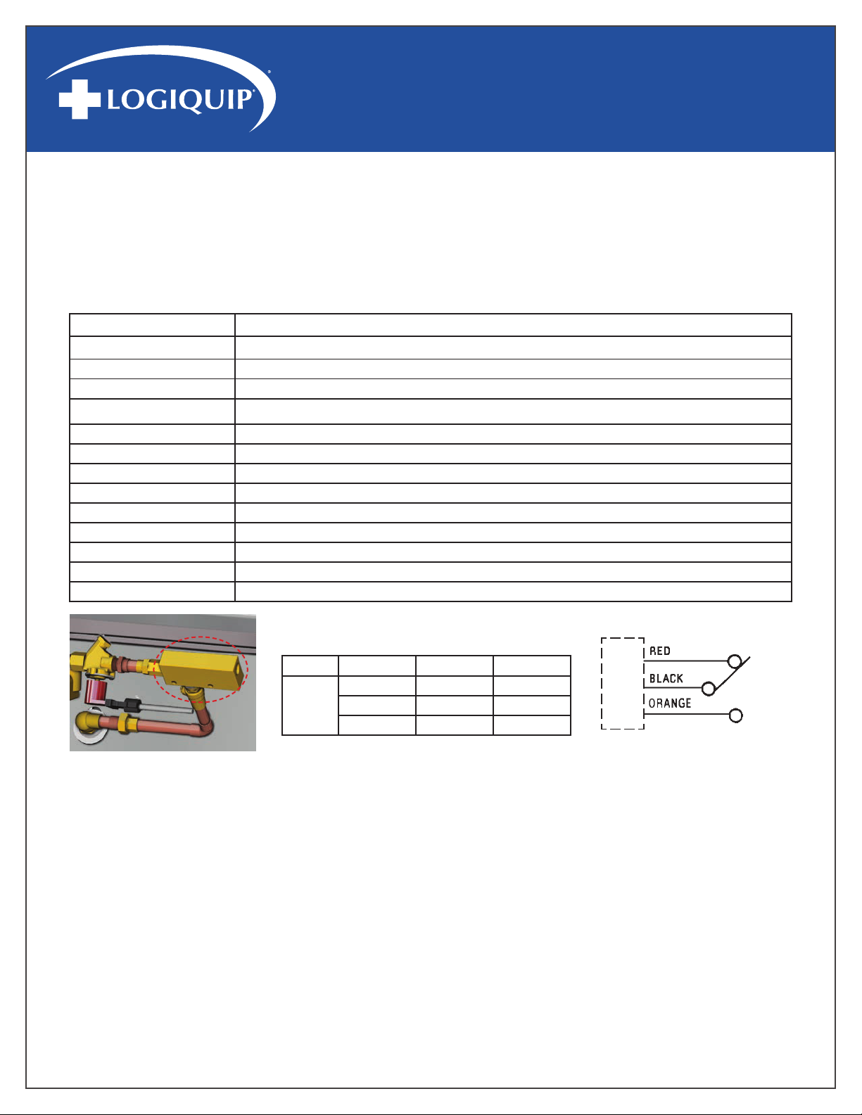
NOTE: This feature (Fig. 1) is available only on Infrared Activated Scrub Sinks.
This is an explosion-proof brass flow switch, actuation setpoint 0.50 GPM (1.89 LPM), and calibrated for water at standard conditions. It
is used for the accurate detection of excessive or insufficient flow rates.
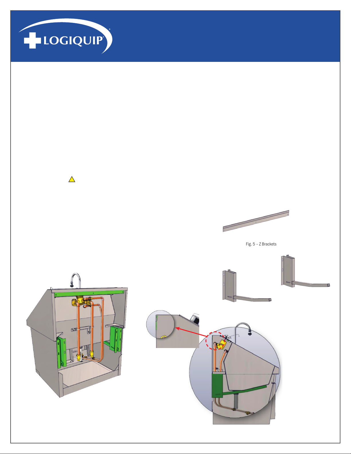
This unit was calibrated in a vertical position, with lead wires up. Install the unit in the piping system, using standard pipe fitting
procedures. Be sure to keep thread sealing compound out of unit. Make sure that flow is in the proper direction - marked “IN” and
“OUT” on housing. See wiring diagrams for electrical connections.
CAUTION: See “Switch Ratings” before connecting power.
CAUTION: Flow settings for this switch is normally calibrated using water @ +70°F on increasing flow. Water-calibrated units are not
recommended for air/gas applications.
SWITCH TIMER CONTROLLER MAINTENANCE
Accumulation of foreign debris should periodically be removed from these switches. Occasional “wipe-down” cleaning when excessive
contamination is present is all that is normally required.
TO CLEAN: Remove unit from system and disassemble as shown below. Clean all parts, reassemble and reinstall unit.
NOTE: 50 micron filtration is recommended.
Fig. 1 – In-Line Flow Timer Controller
Service Compatible liquids
Wetted materials Housing: brass; Piston: polysulfone; Spring: 316SS; O-Ring: Fluoroelastomer, Other: Epoxy.
Temperature Limits -20 to 225°F (-29 to 107°C).
Pressure Limits 1000 psig (68.9 bar).
Accuracy ±10% of set point.
Repeatability ±1%.
Switch Type* SPDT, 20 VA
Electrical Rating .17 A @ 120 VAC, .08 A @ 240 VAC, .13 A @ 120 VDC, .06 A @ 240 VDC.
Electrical Connection 18 AWG, 24" (60.96 cm), Polymeric lead wires.
Process Connection 1/4" female NPT.
Mounting Orientation Any position. Set points shown are based on vertical, inlet down position.
Required Filtration 50 microns or better.
Weight 0.66 lb (301 g).
Agency Approval CE
*Switch Ratings Max Resistive Load
VA Volts Amps AC Amps DC
20
0-30 .4 .3
120 .17 .13
240 .08 .06
AA
CC
BB
Pin Connections for Units with
MS Receptacle
TTyyppiiccaall WWiirriinngg DDiiaaggrraamm
Piston
Inlet Fitting
Housing
Spring
O-Ring
Service Compatible liquids
Wetted materials Housing: brass; Piston: polysulfone; Spring: 316SS; O-Ring: Fluoroelastomer, Other: Epoxy.
Temperature Limits -20 to 225°F (-29 to 107°C).
Pressure Limits 1000 psig (68.9 bar).
Accuracy ±10% of set point.
Repeatability ±1%.
Switch Type* SPDT, 20 VA
Electrical Rating .17 A @ 120 VAC, .08 A @ 240 VAC, .13 A @ 120 VDC, .06 A @ 240 VDC.
Electrical Connection 18 AWG, 24" (60.96 cm), Polymeric lead wires.
Process Connection 1/4" female NPT.
Mounting Orientation Any position. Set points shown are based on vertical, inlet down position.
Required Filtration 50 microns or better.
Weight 0.66 lb (301 g).
Agency Approval CE
*Switch Ratings Max Resistive Load
VA Volts Amps AC Amps DC
20
0-30 .4 .3
120 .17 .13
240 .08 .06
A
A
C
C
B
B
Pin Connections for Units with
MS Receptacle
TTyyppiiccaall WWiirriinngg DDiiaaggrraamm
Piston
Inlet Fitting
Housing
Spring
O-Ring
Service Compatible liquids
Wetted materials Housing: brass; Piston: polysulfone; Spring: 316SS; O-Ring: Fluoroelastomer, Other: Epoxy.
Temperature Limits -20 to 225°F (-29 to 107°C).
Pressure Limits 1000 psig (68.9 bar).
Accuracy ±10% of set point.
Repeatability ±1%.
Switch Type* SPDT, 20 VA
Electrical Rating .17 A @ 120 VAC, .08 A @ 240 VAC, .13 A @ 120 VDC, .06 A @ 240 VDC.
Electrical Connection 18 AWG, 24" (60.96 cm), Polymeric lead wires.
Process Connection 1/4" female NPT.
Mounting Orientation Any position. Set points shown are based on vertical, inlet down position.
Required Filtration 50 microns or better.
Weight 0.66 lb (301 g).
Agency Approval CE
*Switch Ratings Max Resistive Load
VA Volts Amps AC Amps DC
20
0-30 .4 .3
120 .17 .13
240 .08 .06
AA
CC
BB
Pin Connections for Units with
MS Receptacle
TTyyppiiccaall WWiirriinngg DDiiaaggrraamm
Piston
Inlet Fitting
Housing
Spring
O-Ring
*Switch Ratings Max Resistive Load

SCRUB SINKS USE & INSTALLATION GUIDE
www.logiquip.com |7
Fig. 2: SS32 - Single Basin
Fig. 3: SS64 - Double Basin
Fig. 4: SS96 - Triple Basin
SINK DIMENSIONS - SS32, SS64, SS96 MODELS

SCRUB SINKS USE & INSTALLATION GUIDE
(800) 665-3760
8|
INSTALLATION
1. Carefully uncrate the Scrub Sink. The mounting hardware is under the sink, secured to the shipping materials.
• Be sure to remove all hardware before discarding packaging
2. Check water supply and waste terminal locations
• Be sure all connections are safely accessible to the Sink and in proper working condition. NOTE: For proper sink operation the
hot water temperature must be 120° F
• Install Sink near a hot water source
3. Locate Infrared sensor-activated sinks near a 110/120V outlet power source
4. Attach wall mount sink support brackets to the wall
• “Z” Brackets for mounting the sink to the wall come with the sink (Fig. 5). Recommended mounting specifications for Z brackets
shown in Fig. 13 (SS32), Fig. 16 (SS64), and Fig. 19 (SS96) on pages 10-12
• IMPORTANT:
IIccoonn TTyyppeeIIccoonnDDeessccrriippttiioonn
WWaarrnniinnggss(Red triangle with an exclamation point) indicate the potential for minor to
severe injuries up to and including death to personnel.
CCaauuttiioonnss
(Yellow triangle with an exclamation point) indicate the potential for minor
injury to personnel and damage to equipment.
Note: The exclamation point will not be visible where only equipment damage
is present.
BBuurrnn HHaazzaarrdd WWaarrnniinnggss(Yellow triangle with radiating lines) indicate a potential burn injury to personnel.
EElleeccttrriiccaall WWaarrnniinnggss
(Yellow triangle with a lightning bolt) indicate a possible shock hazard is present.
Severe shock hazards shall be a lightning bolt in a red triangle.
For wall-mounted units, the wall structure must be capable of supporting the load
• Optional wall mounting systems (in-wall chair carrier and pedestal-style) and their mounting specifications are shown in Fig. 15
(part S0001 for sink SS32), Fig. 18 (part S0002 for sink SS64), and Fig. 21 (part S0003 for sink SS96) on pages 10-12
5. Install the soap spout on the sink (see page 9)
6. Mount the sink body onto the Z Brackets that were attached to the wall
• A. With the help of an assistant, slide the sink over the “Z” brackets
until it locks securely into place (Fig. 6 - Fig. 7, Z brackets shown in green)
7. Connect the drainpipe to the drain
8. Connect the water supply to the plumbing (page 13)
Fig. 5 – Z Brackets
Fig. 6 – Z Brackets on Sink
Fig. 7 – Cross Section Showing Z Bracket on Sink

SCRUB SINKS USE & INSTALLATION GUIDE
www.logiquip.com |9
Fig. 8 – Soap Spout With Nut And Bushing
Fig. 9 – Install Soap Spout Fig. 10 – Secure Soap Spout with Bushing
Fig. 11 – Install Soap Dispenser Tubing Fig. 12 – Close Up of Soap Pump with Tubing Attached
INSTALLING & OPERATING THE SOAP SPOUT
To prevent damage during shipment, the soap dispenser is stored inside the Sink
Basin. Soap Dispenser tubing is also included. The dispenser spout should be
installed before hanging the Sink.
1. To install - remove the bushing (Fig. 8 - Item 3 shown in green)
2. Feed the spout (item 1) through the small hole at the top of the sink (Fig. 9). The nut
(item 2) should rest on top of the sink
3. Re-install the bushing onto the spout from inside the cabinet (Fig. 10)
4. Attach the soap tubing to the spout and soap pump (circled in red) as shown in Fig. 11
and Fig. 12
To Operate the Soap Pump - press the soap spout down repeatedly to start the flow of the soap.

SCRUB SINKS USE & INSTALLATION GUIDE
(800) 665-3760
10 |
RECOMMENDED MOUNTING SPECIFICATIONS FOR SS32 - 1-STATION SCRUB SINK
For the assembly drawing of In-Line wall Carrier Mount (S0001), see page 21.
Fig. 13 – Z Bracket Mounting Locations - SS32
Fig. 14 – In-Line Wall Carrier Mount - S0001
Fig. 15 – In-Line Wall Carrier Mounting Locations - SS32

SCRUB SINKS USE & INSTALLATION GUIDE
www.logiquip.com |11
RECOMMENDED MOUNTING SPECIFICATIONS FOR SS64 - 2-STATION SCRUB SINK
For the assembly drawing for the In-Line Wall Carrier Mount (S0002), see page 22.
Fig. 17 – In-Line Wall Carrier Mount - S0002
Fig. 16 – Z Bracket Mounting Locations - SS64
Fig. 18 – In-Line Wall Carrier Mounting Locations - SS64

SCRUB SINKS USE & INSTALLATION GUIDE
(800) 665-3760
12 |
RECOMMENDED MOUNTING SPECIFICATIONS FOR SS96 - 3-STATION SCRUB SINK
For the assembly drawing for the In-Line Wall Carrier Mount (S0003), see page 23.
Fig. 20 – In-Line Wall Carrier Mount - S0003
Fig. 19 – Z Bracket Mounting Locations - SS96
Fig. 21 – In-Line Wall Carrier Mounting Locations - SS96

SCRUB SINKS USE & INSTALLATION GUIDE
www.logiquip.com |13
CONNECT DRAINPIPE TO DRAIN AND PLUMBING TO WATER LINES
IIccoonn TTyyppeeIIccoonnDDeessccrriippttiioonn
WWaarrnniinnggss(Red triangle with an exclamation point) indicate the potential for minor to
severe injuries up to and including death to personnel.
CCaauuttiioonnss
(Yellow triangle with an exclamation point) indicate the potential for minor
injury to personnel and damage to equipment.
Note: The exclamation point will not be visible where only equipment damage
is present.
BBuurrnn HHaazzaarrdd WWaarrnniinnggss(Yellow triangle with radiating lines) indicate a potential burn injury to personnel.
EElleeccttrriiccaall WWaarrnniinnggss
(Yellow triangle with a lightning bolt) indicate a possible shock hazard is present.
Severe shock hazards shall be a lightning bolt in a red triangle.
Local building or plumbing codes may require modifications to the information provided. You are required to consult the local
building and plumbing codes before installation. If the information provided here is not consistent with your local building or plumbing
codes, the local codes should be followed. This product must be installed by a licensed contractor in accordance with local codes and
ordinances.
IIccoonn TTyyppeeIIccoonnDDeessccrriippttiioonn
WWaarrnniinnggss(Red triangle with an exclamation point) indicate the potential for minor to
severe injuries up to and including death to personnel.
CCaauuttiioonnss
(Yellow triangle with an exclamation point) indicate the potential for minor
injury to personnel and damage to equipment.
Note: The exclamation point will not be visible where only equipment damage
is present.
BBuurrnn HHaazzaarrdd WWaarrnniinnggss(Yellow triangle with radiating lines) indicate a potential burn injury to personnel.
EElleeccttrriiccaall WWaarrnniinnggss
(Yellow triangle with a lightning bolt) indicate a possible shock hazard is present.
Severe shock hazards shall be a lightning bolt in a red triangle.
FAILURE TO COMPLY WITH PROPER INSTALLATION AND MAINTENANCE INSTRUCTIONS COULD CONTRIBUTE TO VALVE FAILURE.
This hot water master tempering valve cannot be used for tempering water temperature at fixtures. Severe bodily injury (i.e., scalding
or chilling) and/or death may result depending upon system water pressure changes and/or supply water temperature changes. ASSE
standard 1016, 1069, or 1070 listed devices should be used at fixtures to prevent possible injury.
This hot water tempering valve is designed to be installed at or near the boiler or water heater. They are not designed to compensate for
system pressure fluctuations and should not be used where ASSE standard 1016, 1069, or 1070 devices are required. These valves
should never be used to provide “anti-scald” or “anti-chill” service.
The components of the system must be of materials with a construction capable of withstanding the high limit output temperatures of
the water heating source.
IIccoonn TTyyppeeIIccoonnDDeessccrriippttiioonn
WWaarrnniinnggss(Red triangle with an exclamation point) indicate the potential for minor to
severe injuries up to and including death to personnel.
CCaauuttiioonnss
(Yellow triangle with an exclamation point) indicate the potential for minor
injury to personnel and damage to equipment.
Note: The exclamation point will not be visible where only equipment damage
is present.
BBuurrnn HHaazzaarrdd WWaarrnniinnggss(Yellow triangle with radiating lines) indicate a potential burn injury to personnel.
EElleeccttrriiccaall WWaarrnniinnggss
(Yellow triangle with a lightning bolt) indicate a possible shock hazard is present.
Severe shock hazards shall be a lightning bolt in a red triangle.
Need for Periodic Inspection and Yearly Maintenance: Periodic inspection and yearly maintenance by a licensed contractor are
required. Corrosive water conditions, temperatures over 200°F, unauthorized adjustments or repairs could render the valve ineffective
for the service intended. Regular checking and cleaning of the valve’s internal components and check stops helps assure maximum life
and proper product function. Frequency of cleaning and inspection depends upon local water conditions.
PLUMBING INSTALL INSTRUCTIONS
Plumbing Installation should be in accordance with accepted plumbing practices. Installation and field adjustment are the
responsibility of the installer.
1. Flush all pipes thoroughly before installation.
2. Connect sink drainpipe to drain connection.
3. Close both hot and cold water shutoff valves upstream of the tempering valve.
4. Bleed pressure from the system.
5. Route copper tubing or piping to fit valve dimensions.
6. Remove tailpieces from the valve and make sure union nuts are over the tubing/piping before connecting to the tailpiece.
Note: If soldering, remove unions and gaskets from the valve body before soldering to prevent damage to the valve from
excessive heat.
7. Flush piping again, install valve using filter gasket on hot and cold water inlets and fiber gasket on the mixed water outlet.
8. Turn on the cold and hot water. If any leaks are observed, tighten connections as necessary to stop leaks before proceeding.
9. After the plumbing installation is complete, the water pressure can be adjusted to avoid excess splash. The pressure can be
controlled by adjusting the flow with the flow control valve. See Item #4 of the plumbing diagram for the manual knee operated
plumbing on page 15.
10. Feed the spout (Item #1) through the small hole at the top of the sink (Item #9). The nut (Item #2) should rest on top of the sink.
11. Re-install the bushing onto the spout from inside the cabinet (Fig. 10) as shown on page 10.
12. Attach the soap tubing to the spout and soap pump (circled in red) as shown in Fig. 11 and Fig. 12 on page 10.

SCRUB SINKS USE & INSTALLATION GUIDE
(800) 665-3760
14 |
PREVENTATIVE MAINTENANCE
EVERY 6 MONTHS
1. Check and adjust the temperature setting
EVERY 12 MONTHS
1. Shut off the water supply
2. Open up checkstops
3. Clean strainers and check for free movement of checkstop poppet
4. Replace seals if cracked, cut, or worn
5. Re-assemble
6. Adjust stem to the desired temperature
TROUBLESHOOTING
1. If the flow of water is less than desired
• Valves upstream from supply not fully open
• Low supply pressures
• Accumulation of lime deposit is in hot water pipes, restricting the flow of water
• Checkstops not fully open
• Clogged strainer screens in the checkstops
• Clogged cartridge
2. Flow of water is completely cut off
• Valves upstream from supply completely closed
• Failure of cold water supply pressure (mixing value is designed to shut off on a cold water supply failure)
• Checkstops completely closed
3. Flow low is untempered hot or cold water
• Valves Accumulation of time deposits in hot water pipes, restricting the flow of hot water
• Thermostatic actuator failure; replace with new thermostatic actuator
• Hot and cold water supplies are connected to the wrong ports
4. Maximum temperature specified for the mixing valve cannot be obtained
• Accumulation of lime deposits in hot water pipes restricting the flow of hot water
• Hot water supply temperature is too low
5. Variable discharge temperature occurs
• Extreme pressure variations in supply lines
• Valve operating below minimum capacity requirements

SCRUB SINKS USE & INSTALLATION GUIDE
www.logiquip.com |15
8
IItteemm ##DDeessccrriippttiioonnKKnneeee OOppeerraatteeddPPaarrtt ##IInnffrraarreedd AAccttiivvaatteeddPPaarrtt ##
1 Spout For Both Knee Operated or Infrared Activated Plumbing SS0132-01
2 Thermostatic Mixing Valve For Both Knee Operated or Infrared Activated Plumbing S0009
3Mixing Valve Handle For Both Knee Operated or Infrared Activated Plumbing S0010
41/2” Balance Flow Control Valve S0024 Solenoid Valve (for Infrared) S0013
5 Knee Operated Water Valve S0029 Infrared Sensor S0012
6 Inline Flow Switch Timer For Infrared Activated Plumbing S0130-01
7 Checkstop Strainer (L/R) For Both Knee Operated or Infrared Activated Plumbing S0011
8 Swivel Aerator For Both Knee Operated or Infrared Activated Plumbing S0032
9 Soap Spout For Both Knee Operated or Infrared Activated Plumbing S0041
10 Soap Pump Kit For Both Knee Operated or Infrared Activated Plumbing S0028
11 Check Valve For Both Knee Operated or Infrared Activated Plumbing S0131
12 Sink Dividers (not shown) For Both Knee Operated or Infrared Activated Plumbing S0034
REPLACEMENT PARTS FOR MANUAL KNEE OPERATED AND
INFRARED SELF-ACTIVATED SINK PLUMBING
Both plumbing configurations shown below indicate which parts are replaceable. See the table below for replacement part numbers.
Fig. 23 - Infrared Self-Activated Sink Plumbing
Fig. 22 - Manual Knee Operated Sink Plumbing
8
I
I
t
t
e
e
m
m
#
#
D
D
e
e
s
s
c
c
r
r
i
i
p
p
t
t
i
i
o
o
n
n
K
K
n
n
e
e
e
e
O
O
p
p
e
e
r
r
a
a
t
t
e
e
d
d
P
P
a
a
r
r
t
t
#
#
I
I
n
n
f
f
r
r
a
a
r
r
e
e
d
d
A
A
c
c
t
t
i
i
v
v
a
a
t
t
e
e
d
d
P
P
a
a
r
r
t
t
#
#
1 Spout For Both Knee Operated or Infrared Activated Plumbing SS0132-01
2 Thermostatic Mixing Valve For Both Knee Operated or Infrared Activated Plumbing S0009
3Mixing Valve Handle For Both Knee Operated or Infrared Activated Plumbing S0010
41/2” Balance Flow Control Valve S0024 Solenoid Valve (for Infrared) S0013
5 Knee Operated Water Valve S0029 Infrared Sensor S0012
6 Inline Flow Switch Timer For Infrared Activated Plumbing S0130-01
7 Checkstop Strainer (L/R) For Both Knee Operated or Infrared Activated Plumbing S0011
8 Swivel Aerator For Both Knee Operated or Infrared Activated Plumbing S0032
9 Soap Spout For Both Knee Operated or Infrared Activated Plumbing S0041
10 Soap Pump Kit For Both Knee Operated or Infrared Activated Plumbing S0028
11 Check Valve For Both Knee Operated or Infrared Activated Plumbing S0131
12 Sink Dividers (not shown) For Both Knee Operated or Infrared Activated Plumbing S0034

SCRUB SINKS USE & INSTALLATION GUIDE
(800) 665-3760
16 |
INFRARED CONTROLS (FOR INFRARED SELF-ACTIVATED SINKS ONLY)
TROUBLESHOOTING
The sinks are supplied with a 24V power transformer(s) that connects to a standard duplex outlet (110/120V outlet required). 1-Station
sinks have one sensor, dual basin sinks have two sensors (one for each basin) and 3-Station sinks have
three sensors (one for each basin).
1. Plug the transformer(s) into the outlet
2. A red LED will flash in the sensor window (Fig. 29 - circled in red)
IMPORTANT: Do not interrupt the sensor beam until the light turns off
OPERATION
The sensors are pre-set and equipped with a logic board. The sensors determine the
range during the initialization period (The time after initial power until the light turns off
is approximately 5 minutes). The range is approximately 12-14” in front of the sensor
and is 25 degrees at peak.
During the initialization period, the sensors allow for fixed objects that may be within the sensors’
range. The sensors are equipped with a 2-second on/off delay, and no-time-out feature. This
prevents the sink from turning on when walking past at a normal pace and no timeout allows for
an uninterrupted scrub.
SOAP
;,
'
I ·
■·
I
PLUMBING ACCESS ( MANUAL KNEE OPERATED SINKS ONLY)
1. Open the knee panel door by depressing the latch at the bottom of the panel door (Fig. 24).
2. Swing the door fully open to access the hinges (Fig. 25).
3. Push the hinge pins inward to release the door from the hinges (Fig. 26). Infrared Controls (for Infrared Self-Activated Sinks only)
4. To re-attach the door, push in the hinge pins and fit the top corners of the knee panel door onto the left and right hinge leaves
(Fig.27 - circled in red). When the door is refitted, release the hinge pins to secure the door to the sink.
5. The knee panel door should rotate freely on its hinges. Rotate the door back down on its bottom latch to close it (Fig. 28).
Fig. 24 - Push Down Knee
Panel Door Latch Fig. 25 - Door in Fully
Opened Position
Fig. 26 - Push Hinges Inward
Fig. 27 - Left /Right Hinge Leaves
SOAP
;,
'
I ·
■·
I
SOAP
;,
'
I ·
■·
I
Fig. 28 - Door Should
Rotate Freely on Hinges
Fig. 29 - Location of Infrared Sensor

SCRUB SINKS USE & INSTALLATION GUIDE
www.logiquip.com |17
INSTRUCTIONS FOR CLEANING STAINLESS STEEL SURGICAL SCRUB SINKS
Stainless steel sinks must be cleaned on a regular basis to prevent any unnecessary damage to the stainless steel surfaces. When
cleaning stainless steel sinks, make sure to use the proper approved cleaning agents and cleaning materials.
APPROVED CLEANING MATERIALS AND AGENTS
• Soft, clean lint-free cloth
• Non-abrasive cleaning pads
• Soft bristle brush
• Mild detergents
• Sodium Bicarbonate (baking soda)
• Distilled water (pH rating 7) alone or with a mild detergent
• White vinegar (in a spray bottle)
• Isopropyl Alcohol
• Hospital-grade non-bleach disinfectants
• Cleaners approved for use on stainless steel
CLEANING STAINLESS STEEL SURFACES
1. Using a damp, lint-free cloth and approved cleaner, wipe down the entire exterior surface of the stainless steel sinks. Using a
damp, lint-free cloth with distilled water and a mild detergent, wipe down the entire exterior surface of the stainless steel sinks.
2. Let cleaned sinks air dry.
CLEANING DECALS OR PRINTED LABELS
• Use only distilled water and a mild detergent applied with a clean, dry lint-free cloth to clean decals or printed labels.
• Cleaning agents can remove or smear any printing from decals and print labels.
• Cleaning agents can damage plastic materials used in manufacturing covers for electronic items such as infrared sensor face.
C
C
A
A
U
U
T
T
I
I
O
O
N
N
D
D
O
O
N
N
O
O
T
T
U
U
S
S
E
E
these Cleaning Materials
C
C
A
A
U
U
T
T
I
I
O
O
N
N
D
D
O
O
N
N
O
O
T
T
U
U
S
S
E
E
these Cleaning Agents
Abrasive Pads Hard Water (water with a pH reading above 7.0).
Scrapers Hydrochloric Acid
Steel Wool Steam or high pressure water
Wire Brushes Bleach or any compounds containing chlorine or Soldium hypochlorate, or
ammonium chloride salts.

SCRUB SINKS USE & INSTALLATION GUIDE
(800) 665-3760
18 |
OPTIONAL IR TIMER ASSEMBLY
An Electronic IR Timer Assembly (S0202-SST-KT, Fig. 30) can be purchased and in-
stalled on Infrared Activated surgical scrub sinks.
The installation would require some modification of the sink top in order to install.
INSTALLING OPTIONAL ELECTRONIC SINK TIMER DISPLAY
1. To mount the timer housing on the sink top, drill three (3) holes using the hole
dimension sizes and locations as shown in the
illustration (below). Two (2) holes are for mounting the timer housing, one (1) for
threading the three (3) flow-switch timer wires to the top side for connection to the timer readout.
2. Place a grommet in the 0.38” diameter wire threading hole. (Grommet to be supplied by others.)
3. Mount the timer housing to the top of the sink in the 0.31” diameter drilled holes (Fig 31). Mounting studs (0.25” diameter) are
provided on the housing. Secure to sink top with the provided hex nuts.
4. Thread the three (3) flow-switch timer wires through the drilled hole on top of the sink (Fig. 32 - circled in red).
5. Connect the three (3) timer wires (black, red and orange) to the timer read-out terminal connections as shown in Fig. 33.
6. Program the timer as shown on page 19.
Fig. 30 - IR Timer Assembly For IR Scrub Sinks
Fig. 31 - Drill Locations on Sink Top Fig. 32 - Thread Wires Through Grommet Hole
Fig. 33 - Wiring Diagram For Timer
Ø0.31
Ø.31
Ø0.38
SSiinnkk BBaacckk SSiiddee
Sink Left Side
5
6
7
8
4
3
2
1
RReedd WWiirree OOrraannggee
WWiirree
BBllaacckk WWiirree
Ø0.31
Ø.31
Ø0.38
S
S
i
i
n
n
k
k
B
B
a
a
c
c
k
k
S
S
i
i
d
d
e
e
S
S
i
i
n
n
k
k
B
B
a
a
c
c
k
k
S
S
i
i
d
d
e
e
Sink Left Side
5
6
7
8
4
3
2
1
RReedd WWiirree OOrraannggee
WWiirree
BBllaacckk WWiirree
Ø0.31
Ø.31
Ø0.38
SSiinnkk BBaacckk SSiiddee
Sink Left Side
5
6
7
8
4
3
2
1
R
R
e
e
d
d
W
W
i
i
r
r
e
e
O
O
r
r
a
a
n
n
g
g
e
e
W
W
i
i
r
r
e
e
B
B
l
l
a
a
c
c
k
k
W
W
i
i
r
r
e
e
Ø0.31
Ø.31
Ø0.38
SSiinnkk BBaacckk SSiiddee
Sink Left Side
5
6
7
8
4
3
2
1
RReedd WWiirree OOrraannggee
WWiirree
BBllaacckk WWiirree

SCRUB SINKS USE & INSTALLATION GUIDE
www.logiquip.com |19
TIMER OPERATION DISPLAY AND PROGRAMMING
TIME DISPLAY
Accumulates time when the timing start input is active. Timing will not take place when the external or front panel reset is active.
The leftmost digit is the time value legend.
DOWN KEY
When the program input is active the Down Key is used to scroll through the menu items. After a menu item has been chosen for editing,
the Down Key is used to set the value for the currently selected (flashing) digit.
NEXT/RESET KEY
Resets the accumulated time if Front Panel Reset is enabled in Programming Mode. When the program input is active the Next/Reset
Key is used to select a menu item for editing (left most digit will begin to flash) and then move to the desired digit to be changed.
PROGRAMMING
Programming parameters can be accessed, when the Program Enable input is active, by pressing the Down Key. To edit a parameter use
the Down Key to scroll until the desired parameter appears on the screen. Pressing the Next Key key will cause the leftmost digit of that
value to begin to flash. Use the Next and Down Key in combination to choose individual digits and change their value.
FRONT PANEL RESET ENABLE
When active (ON) the time value, when being displayed, can be reset by pressing the Next/Reset Key. If set
to OFF, the time value can only be reset through the remote input.
TIME FORMAT
Sets the units in which the elapsed time will be accumulated. Use the Next Key to scroll through the
available choices: Seconds, Minutes (_ _ _ _ _ . _), Hours (_ _ _ __ . _) , Hours: Minutes: Seconds.
NOTE: On initial start-up, as well as after any programming changes, it is necessary to reset the unit before beginning operation.
MAN-004 18 www.macmedical.com
-ROOT
R
N
N
e
e
x
x
t
t
/
/
R
R
e
e
s
s
e
e
t
t
K
K
e
e
y
y
34567
8S
D
D
o
o
w
w
n
n
K
K
e
e
y
y
EAGLE SIGNAL
on
______
S.
1.
T
T
i
i
m
m
e
e
D
D
i
i
s
s
p
p
l
l
a
a
y
y
MAN-004 18 www.macmedical.com
-ROOT
R
NNeexxtt//RReesseett KKeeyy
345678S
DDoowwnn KKeeyy
EAGLE SIGNAL
on
______
S.
1.
TTiimmee DDiissppllaayy
MAN-004 18 www.macmedical.com
-ROOT
R
NNeexxtt//RReesseett KKeeyy
345678S
DDoowwnn KKeeyy
EAGLE SIGNAL
on
______
S.
1.
TTiimmee DDiissppllaayy

SCRUB SINKS USE & INSTALLATION GUIDE
(800) 665-3760
20 |
TIMER (S0050) SPECIFICATIONS AND TERMINAL CONNECTIONS
The timer is an Elapsed Time Indicator which is powered by an internal 3 volt lithium battery. It comes pre-assembled in its housing and
ready for mounting to the sink.
TIMER BATTERY REPLACEMENT
The unit is shipped with one CR ½ AA size 3V Lithium battery, which is pre-installed. To
change the battery, remove the battery cover by pushing inward and down. Install the
battery in either of the two slots. The unit runs on a single battery, and the second slot
is provided to allow for installing a new battery before removing the old one, retaining
count total and program data. The unit can also be run on two (2) batteries to extend
the battery life to 10 years.
Once the battery is in place the unit will go into a self test mode, and all the segments on
the LCD display will be illuminated. The self test mode is exited by depressing the Next
Key, which will then display the model number (6). Depress the Next Key again to ready
the unit for operation.
Specification Description
Start/Stop Input NPN, Contact Closure; Accumulates time when connected to common; Low State: < 1.0 VDC, High State: > 2.0 VDC
(28VDC max)
Security Input Allows access to panel reset and programming features
Remote Reset Input NPN or Contact Closure to common; level sensitive
Power Source Single or dual 3V Lithium battery; typical 5 years life w/single battery, 10 years w/dual batteries
Ranges & Resolution Seconds, minutes to 1/10, hours to 1/10,hours: minutes: seconds
Display 12mm high, Supertwist LCD; 7 digits; “Low Bat” indicator
Backlighting Green Illumination over whole viewable area. Requires 10 to 28 VDC power source
Dimensions & Mounting See dimensions picture below. Panel Mount with supplied mounting bracket and gasket
Connections Screw terminals
Weight Approximately 64 grams (2.25 ounces)
RReeaarr TTeerrmmiinnaall CCoonnnneeccttiioonnss
TTiimmeerr DDiimmeennssiioonnss ((wwiitthhoouutt mmeettaall hhoouussiinngg))
5
6
7
8
4
3
2
1
72mm (2.83")
68mm (2.66")
33mm
(1.30")
36mm
(1.42")
55.. FFrroonntt PPaanneell PPrrooggrraamm EEnnaabbllee -- AAlllloowwss aacccceessss ttoo
pprrooggrraamm mmooddee wwhheenn ttiieedd ttoo ccoommmmoonn
66.. NNoott UUsseedd
77.. NNoott UUsseedd
88.. DDCC SSuuppppllyy IInnppuutt -- FFoorr bbaacckklliigghhttiinngg
11.. CCoommmmoonn
22.. NNoott UUsseedd
33.. TTiimmiinngg EEnnaabbllee -- NNPPNN oorr ddrryy
ccoonnttaacctt iinnppuuttss
44.. RReemmoottee RReesseett -- RReesseettss ttiimmee vvaalluuee
wwhheenn ttiieedd ttoo ccoommmmoonn
5
6
7
8
4
3
2
1
+
-
10 - 28 VDC
-
+TTAB
+ BATT -
BBaatttteerryy SSlloottss
Specification Description
Start/Stop Input NPN, Contact Closure; Accumulates time when connected to common; Low State: < 1.0 VDC, High State: > 2.0 VDC
(28VDC max)
Security Input Allows access to panel reset and programming features
Remote Reset Input NPN or Contact Closure to common; level sensitive
Power Source Single or dual 3V Lithium battery; typical 5 years life w/single battery, 10 years w/dual batteries
Ranges & Resolution Seconds, minutes to 1/10, hours to 1/10,hours: minutes: seconds
Display 12mm high, Supertwist LCD; 7 digits; “Low Bat” indicator
Backlighting Green Illumination over whole viewable area. Requires 10 to 28 VDC power source
Dimensions & Mounting See dimensions picture below. Panel Mount with supplied mounting bracket and gasket
Connections Screw terminals
Weight Approximately 64 grams (2.25 ounces)
R
R
e
e
a
a
r
r
T
T
e
e
r
r
m
m
i
i
n
n
a
a
l
l
C
C
o
o
n
n
n
n
e
e
c
c
t
t
i
i
o
o
n
n
s
s
T
T
i
i
m
m
e
e
r
r
D
D
i
i
m
m
e
e
n
n
s
s
i
i
o
o
n
n
s
s
(
(
w
w
i
i
t
t
h
h
o
o
u
u
t
t
m
m
e
e
t
t
a
a
l
l
h
h
o
o
u
u
s
s
i
i
n
n
g
g
)
)
5
6
7
8
4
3
2
1
72mm (2.83")
68mm (2.66")
33mm
(1.30")
36mm
(1.42")
5
5
.
.
F
F
r
r
o
o
n
n
t
t
P
P
a
a
n
n
e
e
l
l
P
P
r
r
o
o
g
g
r
r
a
a
m
m
E
E
n
n
a
a
b
b
l
l
e
e
-
-
A
A
l
l
l
l
o
o
w
w
s
s
a
a
c
c
c
c
e
e
s
s
s
s
t
t
o
o
p
p
r
r
o
o
g
g
r
r
a
a
m
m
m
m
o
o
d
d
e
e
w
w
h
h
e
e
n
n
t
t
i
i
e
e
d
d
t
t
o
o
c
c
o
o
m
m
m
m
o
o
n
n
6
6
.
.
N
N
o
o
t
t
U
U
s
s
e
e
d
d
7
7
.
.
N
N
o
o
t
t
U
U
s
s
e
e
d
d
8
8
.
.
D
D
C
C
S
S
u
u
p
p
p
p
l
l
y
y
I
I
n
n
p
p
u
u
t
t
-
-
F
F
o
o
r
r
b
b
a
a
c
c
k
k
l
l
i
i
g
g
h
h
t
t
i
i
n
n
g
g
1
1
.
.
C
C
o
o
m
m
m
m
o
o
n
n
2
2
.
.
N
N
o
o
t
t
U
U
s
s
e
e
d
d
3
3
.
.
T
T
i
i
m
m
i
i
n
n
g
g
E
E
n
n
a
a
b
b
l
l
e
e
-
-
N
N
P
P
N
N
o
o
r
r
d
d
r
r
y
y
c
c
o
o
n
n
t
t
a
a
c
c
t
t
i
i
n
n
p
p
u
u
t
t
s
s
4
4
.
.
R
R
e
e
m
m
o
o
t
t
e
e
R
R
e
e
s
s
e
e
t
t
-
-
R
R
e
e
s
s
e
e
t
t
s
s
t
t
i
i
m
m
e
e
v
v
a
a
l
l
u
u
e
e
w
w
h
h
e
e
n
n
t
t
i
i
e
e
d
d
t
t
o
o
c
c
o
o
m
m
m
m
o
o
n
n
5
6
7
8
4
3
2
1
+
-
10 - 28 VDC
-
+TTAB
+ BATT -
BBaatttteerryy SSlloottss
Specification Description
Start/Stop Input NPN, Contact Closure; Accumulates time when connected to common; Low State: < 1.0 VDC, High State: > 2.0 VDC
(28VDC max)
Security Input Allows access to panel reset and programming features
Remote Reset Input NPN or Contact Closure to common; level sensitive
Power Source Single or dual 3V Lithium battery; typical 5 years life w/single battery, 10 years w/dual batteries
Ranges & Resolution Seconds, minutes to 1/10, hours to 1/10,hours: minutes: seconds
Display 12mm high, Supertwist LCD; 7 digits; “Low Bat” indicator
Backlighting Green Illumination over whole viewable area. Requires 10 to 28 VDC power source
Dimensions & Mounting See dimensions picture below. Panel Mount with supplied mounting bracket and gasket
Connections Screw terminals
Weight Approximately 64 grams (2.25 ounces)
RReeaarr TTeerrmmiinnaall CCoonnnneeccttiioonnss
TTiimmeerr DDiimmeennssiioonnss ((wwiitthhoouutt mmeettaall hhoouussiinngg))
5
6
7
8
4
3
2
1
72mm (2.83")
68mm (2.66")
33mm
(1.30")
36mm
(1.42")
55.. FFrroonntt PPaanneell PPrrooggrraamm EEnnaabbllee -- AAlllloowwss aacccceessss ttoo
pprrooggrraamm mmooddee wwhheenn ttiieedd ttoo ccoommmmoonn
66.. NNoott UUsseedd
77.. NNoott UUsseedd
88.. DDCC SSuuppppllyy IInnppuutt -- FFoorr bbaacckklliigghhttiinngg
11.. CCoommmmoonn
22.. NNoott UUsseedd
33.. TTiimmiinngg EEnnaabbllee -- NNPPNN oorr ddrryy
ccoonnttaacctt iinnppuuttss
44.. RReemmoottee RReesseett -- RReesseettss ttiimmee vvaalluuee
wwhheenn ttiieedd ttoo ccoommmmoonn
5
6
7
8
4
3
2
1
+
-
10 - 28 VDC
-
+TTAB
+ BATT -
B
B
a
a
t
t
t
t
e
e
r
r
y
y
S
S
l
l
o
o
t
t
s
s
This manual suits for next models
2
Table of contents
Other Logiquip Medical Equipment manuals
Popular Medical Equipment manuals by other brands

Innovate
Innovate Fine-Light user guide

laerdal
laerdal Nursing Anne Directions for use

Belmont
Belmont Phot-X II 303 DENTAL X-RAY Operator instructions

Endotronix
Endotronix my cordella manual

Danmeter
Danmeter elpha ii 1000 Practical guide

Blatchford
Blatchford Silcare Walk SWTTCP Series Instructions for use