manuals.online logo
Brands
  1. Home
  2. •
  3. Brands
  4. •
  5. London Electronics
  6. •
  7. Measuring Instrument
  8. •
  9. London Electronics Fusion Series Configuration guide

London Electronics Fusion Series Configuration guide

1
Document Ref:pm65\manuals\Fusion_L Revision:11 Dated: 8 September 2009
Software version F00.14
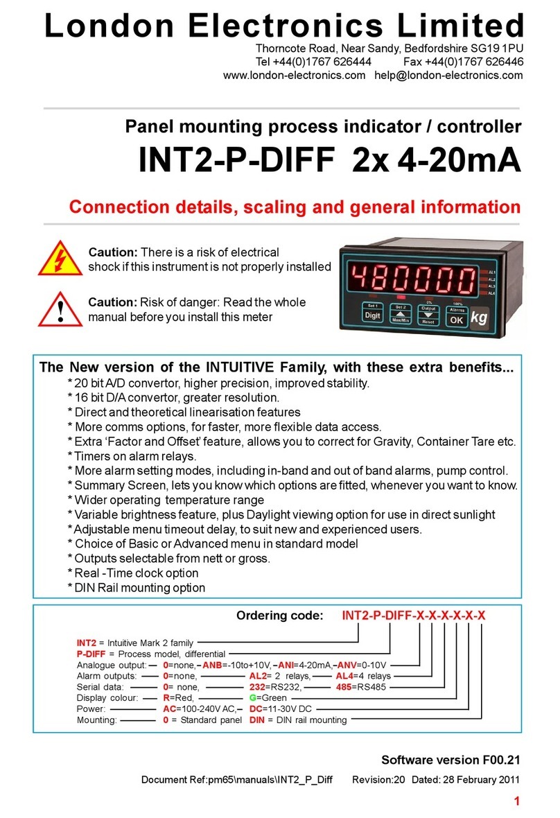
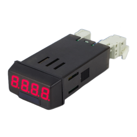
Large digit scalable loadcell / weighing meter
FUSION-L 4 digit version
Connection details, scaling and general information
!
Caution: There is a risk of electrical
shock if this instrument is not properly installed
Caution: Risk of danger: Read the whole
manual before you install this meter
London Electronics Limited
Thorncote Road, Near Sandy, Bedfordshire SG19 1PU
Tel +44(0)1767 626444 Fax +44(0)1767 626446
www.london-electronics.com [email protected]
2
.
3
Alarm board configuration 25
Alarm programming 26-31
Analogue output 23-24
Bootup routine 10
Brightness Adjustment 11
Button Functions 12-13
Calibration - introduction 14
Calibration method - direct, no linearisation 15
Calibration method - direct, with linearisation 20
Calibration method - theoretical, no linearisation 16-17
Calibration method - theoretical, with linearisation 19
Connections 9
Decalaration of conformity 44
General Description 6
Introduction 5
Keyboard timeout Delay 10
Language 10
Logic inputs 34-35
Mounting and Installation 7
Notes 40-43
Option boards- installing 22
Record of revisions 37
Serial output option 32-33
Specifications 36
Warnings 4
WEEE 38
Wiring Advice 8
Zero drift compensation 21
Contents
4
Safety First ..............Don't assume anything............. Always double check.
If in doubt, ask someone who is QUALIFIED to assist you in the subject.
Warnings
Please carefully read this manual and all warnings. Install the display
ONLYwhen you are sure that you’ve covered all aspects.
Check that the model number and supply voltage suit your application
before you install the display.
Connect the display according to current IEE regulations, IEC61010 &
NFPA:70 National Electric Code in USA.
We designed this meter for Pollution-Degree 2 environments.
It is sealed to IP65 NEMA4 all round for wall and suspension mounting
versions with glands on the bottom surface.
Power supplies to this equipment must have anti-surge (T) fuses at
2A for 230V supply, 5A for 110V supply or 5A for DC supplies in the
range 11-30VDC. Aswitch or circuit breaker, clearly marked as a
disconnecting device, must be included close to the installation.
Don’t touch any circuitry after you have connected the display, because
there may be lethal voltages on the circuit board.
Only adjust on-board switches or connections with the power turned off
Make sure all screw terminals are tight before you switch the meter on.
Only clean the display’s case with a soft damp cloth. Only lightly dampen
with water. Do not use any other solvents.
!
!
!
!
!
Rear case screws - please note
The rear panel is held in place with finger-screws, which
only need to be gently tightened.
Do not use tools to tighten or loosen the screws, as
this could cause damage to the internal threads.
5
Introduction
Please contact us if you need help, if you have a complaint, or if you have
suggestions to help us improve our products or services.
If you contact us about a product you already have, please tell us the full
model number and serial number, so that we can give you accurate and fast
help.
This product has a 2 year warranty. We will put right or replace any meter
which is faulty because of bad workmanship or materials. This warranty does
not cover damage caused by misuse or accident.
IMPORTANT
If this equipment is important to your process, you may want to buy a spare to
cover possible failure or accidental damage in the future.
This is because during factory shutdown periods, you may have to to wait
several weeks for an equivalent replacement, or we may have no stock at the
time you urgently need it.
You may also need to pay extra carriage charges if you want a fast, guaranteed
courier service. Warranty repairs or replacements are usually returned with a
standard courier service.
We do not offer compensation for losses caused by failure of this instrument.
If you do not agree with these conditions, please return this item in unused,
condition, in its original packaging and we will refund the purchase price,
excluding any carriage paid.
We thought you’d prefer to know about possible delays and extra charges
now, rather than during a panic. Aspare unit could help to avoid these issues.
We always try to improve our products and services, so these may change
over time. You should keep this manual safely, because future manuals, for
new designs, may not describe this product accurately.
We believe these instructions are accurate, and that we have competently
designed and manufactured the product, but please let us know if you find any
errors.
6
General Description
The FUSION Series of displays accept industrial sensors to allow various
physical measurements to be made, such a weight, temperature, pressure,
humidity etc. Different models are available for different sensor types.
The main function of the FUSION series is to give a large numeric readout of
the variable being monitored. You can choose from various digit sizes and
formats. Most models include an excitation power output, to power the sensor
directly.
Optional output modules are also available, to give alarm relay outputs, analogue
output or digital communications, or any combination of these options.
Displays are programmed using front panel pushbuttons. The buttons may be
locked with a switch. The buttons may also be wired remotely, so that you can
make your settings from ground level.
These displays have two power supply options : 100-240 VAC or 11-30VDC
These units must be installed fully assembled, and must be installed according
to local electrical installation rules. When properly installed, with glands on the
lower surface, they provide ingress protection to IP65 / NMA4X
Safety
Obey all safety warnings in this manual, and install the display according to
local wiring and installation regulations. Failure to follow these guidelines may
cause damage to the display, connected equipment, or may be harmful to
personnel.
Any moving mechanical device controlled by this equipment must have suitable
access guards to prevent injury to personnel if the meter should fail.
!
Caution: There is a risk of electrical
shock if this instrument is not properly installed
Caution: Risk of danger: Read the whole
manual before you install this meter
7
Mounting and Installation
Install your Fusion display according to local electrical regulations.
Mount it away from moving machinery, to minimise the chance of damage, and
keep away from sources of heat, plastics solvents and electrical and magnetic
noise, such as welding equipment, arc lighting, inductive machines etc.
The screws on the back of the display are necessary for sealing - do not omit
any screws.
Do not overtighten screws - it is sufficient to finger-tighten them. In no
circumstance use an electric screwdriver to remove or fit screws, or you will
damage the case threads and sealing will be impaired.
Power cables and alarm relay cables should be routed seaparately to input
signal, logic signal, serial data and analogue output cabling, to minimise the
chances of electrical interference.
8
Only open the case when power has been removed.
This display uses internal detachable screw terminal connectors. Refer to the
wiring diagram on the following page for the correct positioning of each wire.
Each cable is fed through a compression gland for sealing. All glands must be
sealed, unused glands must be plugged.
The conductors you use must be suitable for the meter’s temperature, current
and voltage rating, which is broadly described as follows:-
Cable Temperature Rating
All cables must be rated for operation up to 90C continuous.
Cable gauge
The connectors on this instrument can accept conductors up to 1.5mm2c.s.a.
The minimum cross sectional area shall be 0.5mm2
Cable insulation voltage rating
Cables shall have an insulation voltage rating of at least 380V continuous.
Wire preparation:
We recommend multi-strand wire, because it withstands vibration better than
single strand cable. Pull the wire firmly after you make the connection to confirm
it is tight.
Use screened cable for all signal and control wiring and connect the screen to
earth at the destination end only. Route signal cabling away from power cabling
and relay switching cabling, to avoid electrical noise interference.
Use a single, circular cable through each gland, diameter 4.5 to 6.5mm
Wiring Advice
No bare wires exposed
Terminal screwdiver - 3mm blade
Strip back
5mm max.
London
Electronics
Pull connector
this way to detach
Detachable
connectors
Main board
Function board
Support pillars
9
Connectors and options
Connectors may be present
even if output options are not
installed. Refer to rating label
to see installed options.
!
Connections
Signal Input Board Alarm, Analogue and
Serial comm.s board Power
Board
Analog O/P -
Analog O/P +
Data B / TXD
Data A/ RXD
Common
Enable
Alarm 1
Alarm 1
Alarm 2
Alarm 2
Alarm 3
Alarm 3
Alarm 4
Alarm 4
Excitation -
Sense -
Signal -
Signal +
Sense +
Excitation +
Common
Tare
Peak.Valley
Reset
Sensor Inputs logic Power
Alarm Lock switch
Calib. Lock switch
DC+/AC L
DC- / AC N
n/c
Earth
Contact
closure
From 4 to 8 glands will be fitted, depending on output options installed.
OK Button
Down Button
Up Button
Digit Button
Common
Remote
programming button
connector.
Remove this jumper link to
disable front panel buttons
Board positions
Your display may have its
boards in a different position or
orientation. The pinouts will be
the same as shown,
!
10
Startup meter Settings
Menu Language Choice
Press the two right hand buttons briefly. You will see the User Interface language, which you
can change with the UP or DOWN buttons. Accept with OK
Next you will see ...
Meter Bootup routine
1. Activates all digit segments
2. Runs up and down brightness
settings
3. Displays model number and
installed options
4. Displays firmware version
5.Displays calibration audit
number.
6. Goes to meter mode
When you switch the meter on, it can run through a summary list of software version number,
installed options, calibration number etc.
You can choose from the 3 lists of bootup information to be displayed, the less information
you display, the sooner the meter will be available to operate.
Next you will see ...
Tare Memory
You can configure the meter to store any tared values on power down (Tar.1), typical in
weighing applications, or you can clear the tare memory on power down (Tar.0).
Next you will see ...
Lockout notes: Cal Lock switch = OFF when changing. Switch Cal Lock to ON after changing
L.EnG L.FRA
Bt 0 Bt 1 Bt 2
1. Activates all digit segments
2. Runs up and down brightness
settings
3. Displays model number and
installed options
4. Goes to meter mode
1. Goes immediately to meter
mode
tar.1tar.0
11
Brightness Adjustment
In normal operation, you can select from one of 8 brightness levels, to suit your local lighting
conditions, or to match the brightness of several meters which may be from different batches
or ages.
Press for 3 seconds, then press the down or up button to decrease or increase the
brightness.
Press OK when set.
Your chosen brightness level will be saved in memory, so that the meter will return to the
chosen brightness after power-off.
Lockout notes: Cal Lock switch = ON when changing.
Drift cancellation (Not on INT2-C, INT2-S)
If your meter will normally be showing 0, for example a platform scale, you can set the meter
to continually cancel any long term drift. To do this, set Drf. 1. to remove this feature, select
Drf.0
This only operates at and around zero reading.
The meter will compares readings to previous ones every 30 seconds, and if the value has
changed by a small amount, the meter will aoutomatically re-zero. The maximum movement in
a 30 second period is 8 counts of the least-significant digit. Any more than that, we assume
the change has been a valid process movement, so leave the change unaltered.
drf.0
bril
drf.0
12
Button Functions- ‘Quick-Step’ - Page 1
Functions Buttons Conditions
Cal
AL.CF
8888
8888
8888
Calibration lockout OFF
Can be viewed at any time.
Alarm lockout OFF to
change
Calibration lockout OFF
Calibration Type
Press both buttons >3 secs
Change with UP/DOWN button. OK=Accept
Alarm Settings
Press button briefly to view
>3 seconds to change setpoint
>5 seconds to change function
Analogue Output Settings
Press > 3 seconds to enter
Calibration Zero Setting
Press > 3 seconds to enter
Calibration Span Setting
Press > 3 seconds to enter
brilCalibration lockout ON
Brightness
Press button for 3 seconds
Change with UP/DOWN button. OK=Accept
of.st Calibration lockout OFF
Calibration Offset
Press both buttons >3 secs, press OK 3x
Change with UP/DOWN button. OK=Accept
fact Calibration lockout OFF
Calibration Factor
Press both buttons >3 secs, press OK 2x
Change with UP/DOWN button. OK=Accept
8888 Calibration lockout OFF
Decimal Point position
Press button 3 seconds, set during Cal Span
Change with UP/DOWN button. OK=Accept
13
L.eng
int..p
l.d. 1
Calibration lockout OFF
Can be viewed at any time
Calibration lockout OFF
Button Functions- ‘Quick-Step’ - Page 2
Functions Buttons Conditions
8888 Calibration lockout ON
Link terminals 7,10 and 8
Language& Boot-up mode
Press both buttons briefly
Change with UP/DOWN button. OK=Accept
Hardware & Software summary
Press both buttons >3 secs
Last digit round-up
Press both buttons >3 secs, press OK once
Change with UP/DOWN button. OK=Accept
Reset Peak & Valley memories
Press buttons briefly
dy.10 Calibration lockout OFF
Menu timeout delay
Press both buttons briefly, press OK 3x
Change with UP/DOWN button. OK=Accept
lin.o Calibration lockout OFF
Linearisation
Press both buttons briefly, press
Change with UP/DOWN button. OK=Accept
Fi.0.5 Calibration lockout OFF
Filter time constant
Press both buttons >3 secs
Change with UP/DOWN button. OK=Accept
drf.0 Calibration lockout OFF
Drift Compensation
Press both buttons briefly, press OK 2x
Change with UP/DOWN button. OK=Accept
F.J.10 Calibration lockout OFF
Filter Jump percentage
Press both buttons >3 secs, press OK 1x
Change with UP/DOWN button. OK=Accept
14
Button Functions- ‘Quick-Step’ - Page 3
Functions Buttons Conditions
888888 Calibration lockout ON
Link terminals 7, 10 and 8
Reset Tare
Press buttons briefly 8888
8888 Calibration lockout OFF
8888
8888
Calibration lockout ON and
Link terminals 7 and 8
Calibration lockout ON
Link terminals 7 and 9
Serial Comms setup
Press both buttons briefly
Tare display to 0
Press button briefly. Display shows 0 and the
button LED will illuminate to show you are tared.
Valley & Peak (Max. & Min.)
Press button briefly, once for peak, next for
valley.
tar.1Calibration lockout OFF
Tare Storage
Press both buttons briefly, press OK once
Change with UP/DOWN button. OK=Accept
rEv.0 Calibration lockout OFF
Reverse / Mirror display
Press both buttons briefly, press OK 5x
Change with UP/DOWN button. OK=Accept
15
Filter settings
You can use the filter to improve display stability. This is useful if your signal is unstable. Bigger
time constants give more stability but slower response.
The Time constant of this digital filter is very similar to the time constant of an RC filter where
T=RC . The time constant is the time it takes for the display to reach 63 % of its final reading
value, after a step change on the input.
You will see that if you select a 1 second filter time, it will take several seconds for the meter to
reach its final value.
To give improved response to large step changes, we can momentarily cancel the filter action
with the ‘Filter Jump’ feature
How does the Filter Jump feature work?
First, make a note of the range you calibrated your meter over (not the full dynamic range of the
meter, just the the difference between the maximum and minimum display values you set, in
either direct or theoretical calibration) Let’s assume you calibrated the meter for a 250 range.
If you set the filter jump percentage to 25%, any sudden change in input of less than 25% of 250
will be included in the averaging calculation.
However, a jump of greater than 25% will cause the filter to be ignored and the meter will
immediately jump to that new value.
If you set a jump of 0%, filtering will always be overridden (never any filtering)
If you set a jump of 99%, filtering will always be present, so long as the input signal doesn’t jump
more than 99% of the calibrated range.
Fi.0.5 Calibration lockout OFF
Filter time constant
Press both buttons >3 secs
Change with UP/DOWN button. OK=Accept
F.J.10 Calibration lockout OFF
Filter Jump percentage
Press both buttons >3 secs, press OK 1x
Change with UP/DOWN button. OK=Accept
16
Calibration Methods - introduction
Calibration lockout switch must be OFF to view
and/or change calibration.
Press Set1 and Set2 buttons at the same time...
There are two ways you can calibrate your display, and each way can be done with 2 points
only, or up to 10 linearisation points.
A. Direct connection of real-time low and high input signal levels, which you
scale the display against. (Zero and Span)
B. Theoretical scaling, where you use the keyboard to enter expected zero and
full scale sensor signals, and the measurement amounts these relate to .
After a couple of seconds,
display shows...
Press UP or DOWN arrow to change Press UP or DOWN arrow to change
Press OK to choose. Press OK to choose.
Examples of Theoretical Calibration...
1. If you do not yet have your sensor, but know what
its published calibration settings are.
For example, you plan to use a pressure sensor,
which will give 0-20mV for 0-250 kg. You can
enter the input range of 0-20mV and the
measurement range of 0-250.
2. If you are a distributor, supplying adisplay to
an end user who will be buying his sensor from
another source. He has told you on his order what
he would like the scaling to be.
Shortly after CAL.SrC appears, the
display will change to show either dIrECt
or tHEor as below.
When you have chosen the Calibration type, it will be saved in your display’s memory, so you
will not need to repeat the procedure.
You may now calibrate your display using your preferred method, on the following pages.
..
Examples of Direct Calibration...
1. If you want to calibrate a weighing system by
loading it with known calibration weights.
2. If you want to calibrate a straight-sided tank
gauging system by filling the tank with a known
amount of liquid.
3. If you are performing a calibration check against
a calibration reference, such as humidity cells, pH
buffers etc.
Press
button
to toggle
8888
dir theo
17
Direct Calibration, no linearisation
Set your calibration method to DIRECT - see previous page.
Assume we want to calibrate a weighing platform, rated at 250kg. We have a 200kg calibration
weight. (Use at least 60% rated load for calibration. 100% ideally)
First, calibrate the full scale (SPAN) reading. We do SPAN first, because in the SPAN procedure we
can set the decimal point position of our measurement, to set resolution.
SPAN Calibration . Apply your calibration load and press the Set2 button for 3 seconds.
Display will show ‘direct’ , ‘set HI’ . Press OK. You will see that one digit is brighter than the others.
You can edit the value of a brightened digit with the UP/DOWN buttons.
You can brighten other digits with the DIGIT button.
Go through each digit in turn, to set the desired value of your calibration load.
Press OK when done.
To set the decimal point position, press the Set2 button for 3 seconds whilst in the numeric
setting stage . You’ll see all decimal points light, with one brighter than the rest. Use UP or DOWN
buttons to move the brightest decimal point and press OK when in the desired position.
ZERO Calibration. Remove your load and press the Set1 button for 3 seconds.
Display will show ‘direct’ , ‘set LO’ . Press OK. You will see that one digit is brighter than the others.
You can edit the value of a brightened digit with the UP/DOWN buttons.
You can brighten other digits with the DIGIT button.
Go through each digit in turn, to set all digits to 0. Press OK when done.
200 kg
200 kg
200 kg
200 kg
Enter your calibration weight value.
Press OK
when done.
Example only
Example only
200.0
000.0
Lockout notes: Cal Lock switch = OFF when changing. Switch Cal Lock to ON after changing
18
Theoretical Cal., no linearisation - page 1
Set your calibration method to THEORETICAL - see previous pages
As an example, let us assume we want to calibrate the display for a pressure sensor input.
Let us also assume that we know from the calibration sheet which came with the pressure
sensor, that it has an output of 0-20mV and a rated capacity of 0 to 50 kg
.
We need to enter these figures into the display...
Start with the full scale SPAN setting...
Press the Set2 button for around 3 seconds.
The display will briefly show theor, to confirm that we
are in the theoretical setup mode.
Choose with the up or down arrows and press OK.
Set to highest input signal level which was
20mA, according to the sensor calibration
sheet in our example.
You can change the value of the brightest
digit with the UP or DOWN buttons.
Brighten other digits with the DIGIT button.
Press OK when done...
In HI will appear briefly, followed by a numeric
value, which you can set...
The numeric value will need to be the High
input signal level ...
theo
in.hi 20.00
Lockout notes: Cal Lock switch = OFF when changing. Switch Cal Lock to ON after changing
19
rd HI will appear briefly, followed by a
numeric value, which you can set...
The numeric value will need to be the High
display reading value ...
Set to highest reading value, which was 50
according to the sensor calibration sheet in
our example.
You can change the value of the brightest
digit with the UP or DOWN buttons.
Brighten other digits with the DIGIT button.
Press OK when done...
You can change the position of the decimal point,
relating to rd HI (and rd LO)
This may be useful if you want to increase the
resolution of the display.
The resolution affects several of the display’s
important functions, such as ....
...the resolution of the analogue output signal
...the resolution of your alarm relay action.
...the resolution of the serial data output value.
As an example, assume you have a sensor with 10
tonne capacity.
If you scale the display for 0 to 10, the resolution will
only be 1 part in 10
Your analogue output will change in 10% steps.Your
precision of alarm setting would be to within 1 tonne.
The resolution of serial data would be within 1 tonne.
However, if you include a decimal point you could
control the resolution, as in these examples :-
0-10.0 which gives 1% resolution
0-10.00 which gives 0.1% resolution
0-10.000 which gives 0.01% resolution
You cannot get more resolution than 1 part in 60000.
This is the limit of resolution in the A/D converter.
Note: If you change the decimal point position, you
must reset the rdLO and rdHI values also.
Next .... how to set the theoretical ZERO calibration...
Theoretical cal., no linearisation - page 2
To change decimal point position, press the Set2
button for around 3 seconds while you’re in the rdHI
setup...
Use the UP arrow button to move the decimal point to
your desired position.
Press OK when done.
....Continued from previous page
rd.hi 5000
5.0.0.0.
50.00
20
Theoretical cal., no linearisation - page 3
Press the Set1 button for around 3 seconds.
theor will appear briefly, to confirm that you
are in the theoretical calibration mode.
The numeric value will need to be the low
input signal value ...
Next, In Lo will appear briefly. Set to the
low input value, which was 4mA according
to the sensor calibration sheet in our
example.
You can change the value of the brightest
digit with the UP or DOWN buttons.
Brighten other digits with the DIGIT button.
Press OK when done...
rd LO will now appear briefly, followed by a
numeric value, which you can set...
The numeric value will need to be the low
reading value ...
Set to the low reading value, which was
0kg according to the sensor calibration
sheet in our example.
You can change the value of the brightest
digit with the UP or DOWN buttons.
Brighten other digits with the DIGIT button.
Press OK when done...
This completes the Theoretical calibration routine. Please remember to switch the Calibration
Lockout switch ON
Continued from previous pages. ZERO setting ...
theo 00.00
rd.lo0000

Other manuals for Fusion Series

2

This manual suits for next models

1

Other London Electronics Measuring Instrument manuals

London Electronics INTUITIVE INT2 Series Configuration guide

London Electronics

London Electronics INTUITIVE INT2 Series Configuration guide

London Electronics ASR-GPS Configuration guide

London Electronics

London Electronics ASR-GPS Configuration guide

London Electronics INT2-P-DIFF User manual

London Electronics

London Electronics INT2-P-DIFF User manual

London Electronics ADEPT5 mk.2 User manual

London Electronics

London Electronics ADEPT5 mk.2 User manual

London Electronics IL2-L Configuration guide

London Electronics

London Electronics IL2-L Configuration guide

London Electronics PICA-P User manual

London Electronics

London Electronics PICA-P User manual

London Electronics INTUITIVE INT4-P Installation instructions

London Electronics

London Electronics INTUITIVE INT4-P Installation instructions

London Electronics Fusion-P User manual

London Electronics

London Electronics Fusion-P User manual

London Electronics INT-AH User manual

London Electronics

London Electronics INT-AH User manual

London Electronics Fusion-L 6 digit Configuration guide

London Electronics

London Electronics Fusion-L 6 digit Configuration guide

London Electronics MAXI-INT2-L Mk.2 User manual

London Electronics

London Electronics MAXI-INT2-L Mk.2 User manual

London Electronics Intuitive INT4-AH Installation instructions

London Electronics

London Electronics Intuitive INT4-AH Installation instructions

Popular Measuring Instrument manuals by other brands

Schmidt SS 20.515 LED Instructions for use

Schmidt

Schmidt SS 20.515 LED Instructions for use

MREL MicroTrap Operation manual

MREL

MREL MicroTrap Operation manual

Yamaha YPDR601 operating manual

Yamaha

Yamaha YPDR601 operating manual

Yamato Body Planner DF870 Operation manual

Yamato

Yamato Body Planner DF870 Operation manual

Advanced Bilirubin Stat-Analyzer BR2 Service manual

Advanced

Advanced Bilirubin Stat-Analyzer BR2 Service manual

Hanna Instruments Chromium VI quick start guide

Hanna Instruments

Hanna Instruments Chromium VI quick start guide

GW Instek GSP-818-TG user manual

GW Instek

GW Instek GSP-818-TG user manual

TPI DC710 manual

TPI

TPI DC710 manual

GHM Delta OHM LPPYRA12 operating manual

GHM

GHM Delta OHM LPPYRA12 operating manual

VOLTCRAFT ENERGY LOGGER 3500 operating instructions

VOLTCRAFT

VOLTCRAFT ENERGY LOGGER 3500 operating instructions

Bühler technologies GAS 222.21 Assembly, installation and operation instructions

Bühler technologies

Bühler technologies GAS 222.21 Assembly, installation and operation instructions

Kane KM9106 Operator's manual

Kane

Kane KM9106 Operator's manual

Meggitt VM600 manual

Meggitt

Meggitt VM600 manual

Enpaix EFGS series user manual

Enpaix

Enpaix EFGS series user manual

Endress+Hauser Waterpilot FMX21 operating instructions

Endress+Hauser

Endress+Hauser Waterpilot FMX21 operating instructions

Hanna Instruments HI 96702 instruction manual

Hanna Instruments

Hanna Instruments HI 96702 instruction manual

ACS A1207D user manual

ACS

ACS A1207D user manual

LaserLiner AutoSmart-Laser instruction manual

LaserLiner

LaserLiner AutoSmart-Laser instruction manual

manuals.online logo
manuals.online logoBrands
  • About & Mission
  • Contact us
  • Privacy Policy
  • Terms and Conditions

Copyright 2025 Manuals.Online. All Rights Reserved.