manuals.online logo
Brands
  1. Home
  2. •
  3. Brands
  4. •
  5. LOVATO ELECTRIC
  6. •
  7. Measuring Instrument
  8. •
  9. LOVATO ELECTRIC DME D121 User manual

LOVATO ELECTRIC DME D121 User manual

I390 GB D 02 17 31100194
1
WARNING!
– Carefully read the manual before the installation or use.
– This equipment is to be installed by qualified personnel, complying to current standards, to avoid damages or safety
hazards.
– Remove eventual dangerous voltage from the product before any maintenance operation on it.
– The manufacturer cannot be held responsible for electrical safety in case of improper use of the equipment.
– Products illustrated herein are subject to alteration and changes without prior notice. Technical data and descriptions
in the documentation are accurate, to the best of our knowledge, but no liabilities for errors, omissions or
contingencies arising therefrom are accepted.
– A circuit breaker must be included in the electrical installation of the building. It must be installed close by the
equipment and within easy reach of the operator.
It must be marked as the disconnecting device of the equipment: IEC /EN 61010-1 § 6.11.
– Fit the instrument in an enclosure or cabinet with minimum IP51 degree protection.
– Clean the instrument with a soft dry cloth, do not use abrasives, liquid detergents or solvents.
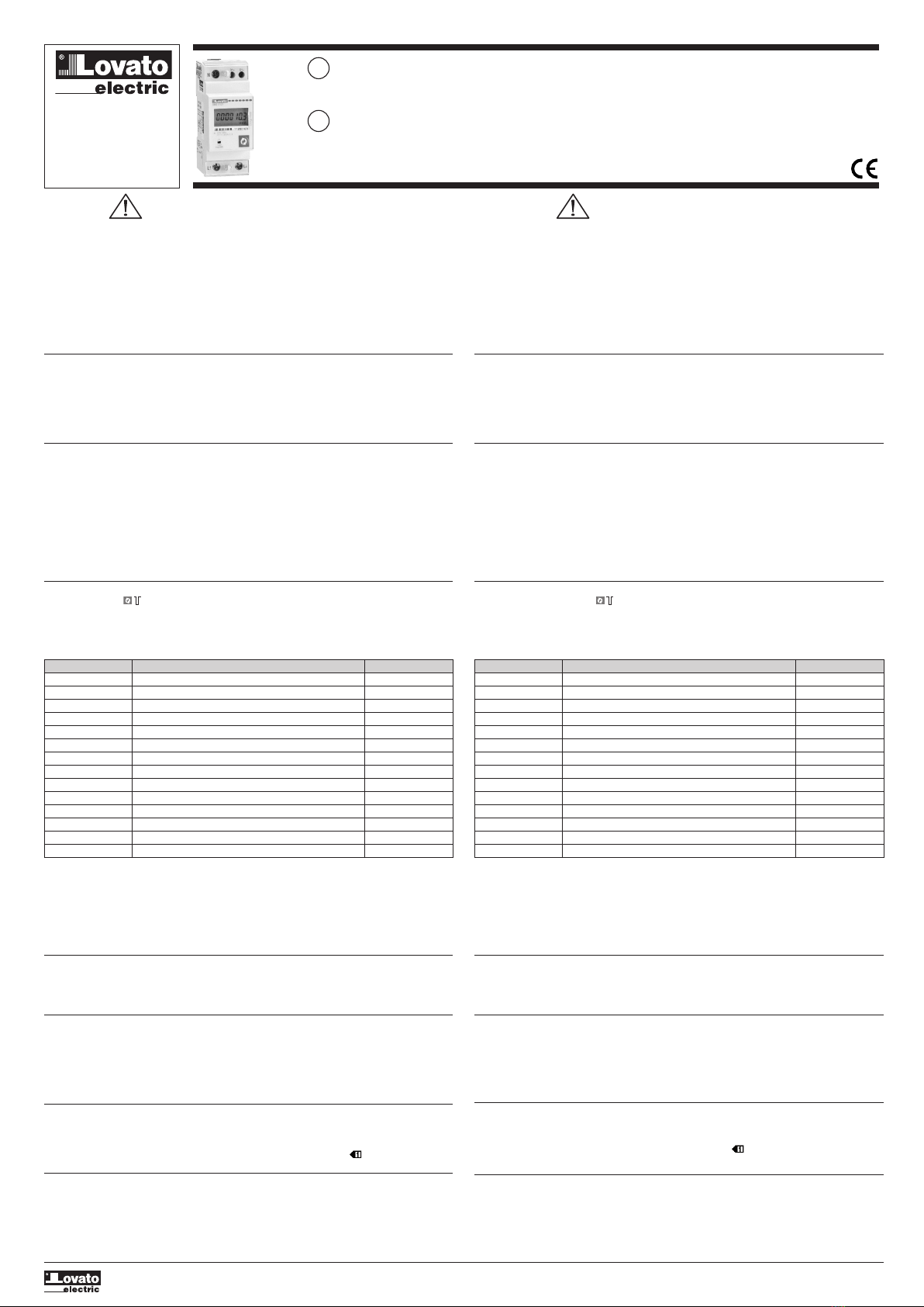
INTRODUCTION
The DME D121 is a single-phase active and reactive energy meter for direct connection, for currents up to 63A, equipped
with a built-in RS-485 serial interface.
The energy accuracy is compliant with standard EN50470-3 class B.
Apart from energy metering, it can measure additional indications, for a total of 14 measurements that can be visualized on
the backlighted LCD display.
The DME D121 has a standard 2U (36mm wide) modular housing and is supplied with sealable terminal blocks.
DESCRIPTION
– Modular DIN-rail housing, 2U (36mm wide).
– Direct connection for currents up to 63A.
– Active energy measure complies EN50470-3 class B.
– LCD display with backlight.
– Counter with 6+1 digits.
– Button for measure selection and programming.
– Total active and reactive energy meters.
– Partial active and reactive energy meters, resettable.
– Hour counter, total and partial.
– Pulse LED for active energy consumption.
– Indication of instantaneous consumption (active power).
– RS-485 interface with Modbus RTU and ASCII protocols.
SELECTION OF READINGS
– Pressing briefly the button it is possible to select the readings on the display, following the sequence in the table
reported below.
– Each measure is indicated by the correspondent icon in the lower part of the display.
– After one minute has elapsed after the last keystroke, the display moves automatically back to the total active energy
screen.
ACHTUNG!!
– Diese Betriebsanleitung vor Gebrauch und Installation aufmerksam lesen.
– Zur Vermeidung von Personen- und Sachschäden dürfen diese Geräte nur von qualifiziertem Fachpersonal und unter
Befolgung der einschlägigen Vorschriften installiert werden.
– Vor jedem Eingriff eventuell am Gerät anliegende gefährliche Spannungen trennen.
– Bei zweckwidrigem Gebrauch der Vorrichtung übernimmt der Hersteller keine Haftung für die elektrische Sicherheit.
– Die in dieser Broschüre beschriebenen Produkte können jederzeit weiterentwickelt und geändert werden. Die im
Katalog enthaltenen Beschreibungen und Daten sind daher unverbindlich und ohne Gewähr.
– In die elektrische Anlage des Gebäudes ist ein Ausschalter oder Trennschalter einzubauen. Dieser muss sich in
unmittelbarer Nähe des Geräts befinden und vom Bediener leicht zugänglich sein. Er muss als Trennvorrichtung für das
Gerät gekennzeichnet sein: IEC/ EN 61010-1 § 6.11.
– Das Instrument in einem Gehäuse und/oder in einer Schalttafel mit Mindestschutzart IP51 installieren.
– Das Instrument mit einem weichen Tuch reinigen, keine Scheuermittel, Flüssigreiniger oder Lösungsmittel verwenden.
VORWORT
Der DME D121 ist ein einphasiger Energiezähler mit Direktanschluss für Ströme bis zu 63A und serieller Schnittstelle
RS-485.
Die Energiemessung erfüllt die Bestimmungen der Norm EN 50470-3 Klasse B.
Neben der Energiemessung liefert das Gerät weitere Angaben für insgesamt 14 Messungen, die auf dem großen
LCD-Display mit Hintergrundbeleuchtung angezeigt werden können.
Der DME D121 hat ein modulares Standardgehäuse der Breite 2U (36 mm) und ist serienmäßig mit plombierbaren
Klemmenabdeckungen ausgestattet.
BESCHREIBUNG
– Modulare Ausführung 2U (36mm) für DIN-Schiene.
– Direktanschluss für max. Ströme 63A.
– Wirkenergiemessung gemäß EN 50470-3 Klasse B.
– LCD-Display mit Hintergrundbeleuchtung.
– Zähler mit 6+1 Ziffern.
– Taste für die Wahl der Messungen und Programmierung.
– Wirk- und Blindenergiezähler (Gesamt).
– Energiezähler (Teil, rücksetzbar).
– Gesamt- und Teilstundenzähler.
– Impulsgesteuerte, frontseitige LED für die verbrauchte Wirkenergie.
– Anzeige Momentanverbrauch (Wirkleistung).
– Schnittstelle RS-485 mit Protokoll Modbus RTU und ASCII.
WAHL DER MESSUNGEN
– Durch kurzes Drücken der Taste können die Messungen auf dem Display des Instruments gemäß der in der
nachstehenden Tabelle angegebenen Sequenz gewählt werden.
– Jede Wahl wird mit der jeweiligen Maßeinheit vom entsprechenden Symbol im unteren Display-Abschnitt angezeigt.
– Nachdem die Taste an der Vorderseite eine Minute lang nicht gedrückt wurde, wechselt die Messung wieder auf den
Gesamt-Wirkenergiezähler.
Icon Measurement Format
kWh Total active energy 000000,0
kWh + Part Partial active energy 000000,0
kvarh Total reactive energy 000000,0
kvarh + Part Partial reactive energy 000000,0
V Voltage 000,0
A Current 00,00
kW Active power 00,00
kvar Reactive power 00,00
PF Power factor 0,00
Hz Frequency 00,0
h ❶ Hour counter (hhhhh.mm) 00000,00
h + Part ❶ Partial hour counter (hhhhh.mm) 00000,00
kW +d ❷ Average active power (15 min demand) 00,00
kW+d+❷ Max avg. active power (max demand) 00,00
Symbol Messung Format
kWh Gesamtwirkenergie 000000,0
kWh + Part Teilwirkenergie 000000,0
kvarh Gesamtblindenergie 000000,0
kvarh + Part Teilblindenergie 000000,0
V Spannung 000,0
A Strom 00,00
kW Wirkleistung 00,00
kvar Blindleistung 00,00
PF Leistungsfaktor 0,00
Hz Frequenz 00,0
h ❶ Stundenzähler (hhhhh.mm) 00000,00
h + Part ❶ Teilstundenzähler (hhhhh.mm) 00000,00
kW +d ❷ Durchschn. Wirkleistung (Leistung in 15 Min.) 00,00
kW+d+❷ Max. durchschn. Wirkleistung (max. Leistung) 00,00
∂ These measurements are shown only enabling parameter P-08
∑ These measurements are shown only enabling parameter P-09
❶ Diese Messungen sind nur sichtbar, wenn der Parameter P-08 aktiviert wird
❷ Diese Messungen sind nur sichtbar, wenn der Parameter P-09 aktiviert wird
DME D121
GB
EINPHASIGER ENERGIEZÄHLER MIT DIREKTANSCHLUSS MIT SCHNITTSTELLE RS-485
Installationshandbuch
D
LOVATO ELECTRIC S.P.A.
24020 GORLE (BERGAMO) ITALIA
VIA DON E. MAZZA, 12
TEL. 035 4282111
TELEFAX (Nazionale): 035 4282200
TELEFAX (International): +39 035 4282400
E-mail info@LovatoElectric.com
Web www.LovatoElectric.com
SINGLE-PHASE DIRECT CONNECTION ENERGY METER WITH RS-485 INTERFACE
Installation manual
METROLOGICAL LED
– The red LED on the front emits 1000 pulses for every kWh of consumed Energy (that is, one pulse every Wh).
– The pulsing frequency of the LED gives an immediate indication of the energy flowing in every moment.
– The pulse duration, LED colour and intensity are compliant with the reference standards that define its utilization in
order to verify the accuracy of the energy meter.
ENERGY FLOW INDICATION
– When the device detects a flow of active energy to the load, it shows a rotating icon in the top-right part of the display.
– When there is no active energy consumption or when the load draws less than the starting current the rotating icon
disappears.
RS-485 INTERFACE
– Via the RS-485 interface the value of energy meters and can be read from DMED121 as well as all other measures.
– The device acts as a standard Modbus slave.
– The configuration of the serial communication is done with the setup parameters from P-20 to P-24.
– The map of the measures on the Modbus protocol is shown in the following Modbus address table chapter. For a more
detailed description, see technical instruction I315 (downloadable from website).
– For wiring diagrams, see the end of this manual.
PROGRAMMABLE LIMIT THRESHOLD
– Through parameters from P-02 to P-07 it is possible to define the behaviour of a programmable limit threshold, whose
status can be read from the communication protocol (see modbus addresses table).
– The programmable limit threshold can be used for instance to signal alarm situation to a remote device.
– The activation of the programmable limit threshold is shown on the display through the icon.
– Note: During parameter setting (setup) the status of the programmable limit threshold is not updated.
INCORRECT WIRING INDICATION
– In case of incorrect wiring, when the device detects a reverse energy flow, the display shows the blinking code Err 3.
– This error is caused by either reverse connection of current wires (terminals Land L) or reverse voltage wiring
(terminals N - L).
– In these conditions, the energy is not counted.
METROLOGISCHE LED AN DER VORDERSEITE
– Die rote LED an der Vorderseite gibt 1000 Impulse pro kWh verbrauchte Energie ab (d.h. 1 Impuls pro Wh).
– Die Blinkfrequenz der LED liefert eine unmittelbare Angabe über den Umfang der in einem bestimmten Augenblick
angeforderten Leistung.
– Die Dauer des Blinkimpulses sowie die Farbe und Leuchtstärke der LED entsprechen den Normen, die ihre
Verwendung zwecks metrologischer Überprüfung der Genauigkeit des Energiezählers vorschreiben.
ENERGIEFLUSSANZEIGE
– Wenn das Instrument einen Energiefluss zur Last misst, erscheint auf dem Display in der rechten oberen Ecke ein
drehendes Symbol.
– Wenn die Last keine Wirkenergie erfordert, oder wenn die Stromaufnahme geringer als der Anlaufstrom ist,
verschwindet das drehende Symbol.
SCHNITTSTELLE RS-485
– Über die Schnittstelle RS-485 kann vom DMED121 sowohl der Wert der Energiezähler als auch alle anderen
Messungen abgelesen werden.
– Das Gerät verhält sich wie ein Standard Slave Modbus.
– Die Parametrisierung der seriellen Kommunikation erfolgt mit den Setup-Parametern von P-20 bis P-24.
– Die Karte der Messungen am Modbus-Protokoll ist im folgenden Kapitel „Tabelle der Modbus-Adressen“ aufgeführt.
Für eine genauere Beschreibung wird auf die technische Anleitung I315 verwiesen (die von der Website
heruntergeladen werden kann).
– Die Anschlusspläne befinden sich am Ende dieses Handbuchs.
PROGRAMMIERBARER GRENZWERT
– Über die Parameter von P-02 bis P-07 kann das Verhalten eines programmierbaren Grenzwerts festgelegt werden,
dessen Status über das Kommunikationsprotokoll abgelesen werden kann (siehe Tabelle der Modbus-Adressen).
– Der programmierbare Grenzwert kann beispielsweise für Fernalarmierungen verwendet werden.
– Die Aktivierung des programmierbaren Grenzwerts wird mit dem Symbol auf dem Display angezeigt.
– Hinweis: Während der Parametereinstellung (Setup) wird der Status des programmierbaren Grenzwerts nicht
aktualisiert.
ANZEIGE FALSCHER ANSCHLUSS
Wenn das Gerät falsch angeschlossen wurde und ein Energiefluss in die falsche Richtung erfasst wird, wird die
blinkende Anzeige Err 3 aktiviert.
Dieser Fehler kann durch Vertauschen des Stromanschlusses (Klemmen L↑und L↓) oder durch Vertauschen der
Spannungsklemmen (N - L↑) verursacht werden.
Unter diesen Bedingungen wird die Energie nicht gezählt.
I390 GB D 02 17 31100194
2
NAVIGATION WITH FRONT KEY
– To move through menus, use the following rules:
– A short click of the front key, indicated by , changes the current selection, shown on the display, with a new one
(the next).
– Pressing the key for a long time (> 3s), indicated with symbol , is used to confirm the displayed selection.
– Symbol indicates when the user must wait for the display to move to a new selection.
– To quit a menu, select the --ESC-- option.
ADVANCED FUNCTIONS
– To access the advanced functions, use the following procedure:
1. Starting from any visualization screen, press . If the password protection is disabled (factory default, password =
0000), display jumps directly to point 4, otherwise it will show PASS to inform that the access code must be entered
first.
2. Release the button. The display now waits for the password and indicates 0000. The single digits are flashing
sequentially. Pressing while a digit is flashing, that digit is incremented. Waiting for some seconds, the selection
moves to the next digit. After having entered the right password code, press to confirm.
3. If the entered password is wrong, the display shows PASS Er and goes back to normal visualization. If instead the
code is correct, it proceeds to next point.
NAVIGATION MIT DER VORDEREN TASTE
– Für das Navigieren zwischen den Menüs gelten die folgenden Regeln:
– Mit einem kurzen Druck der Taste an der Vorderseite, hier mit dem Symbol kenntlich gemacht, wird von der
momentan angezeigten Auswahl auf eine andere, darauf folgende gewechselt.
– Mit einem anhaltenden (> 3s) Tastendruck, hier mit dem Symbol kenntlich gemacht, wird die angezeigte Auswahl
bestätigt.
– Das Symbol erscheint, wenn gewartet werden muss, bis das Display eine neue Auswahl bereitstellt.
– Zum Beenden des Menüs die Option --ESC-- wählen.
ERWEITERTE FUNKTIONEN
– Für den Zugang zu den erweiterten Funktionen folgendermaßen vorgehen:
1. Von einer beliebigen Bildschirmseite auf drücken. Wenn der Passwortschutz deaktiviert ist (Werkseinstellung,
Passwort = 0000) wechselt das Display direkt zu Punkt 4, andernfalls erscheint die Anzeige PASS, mit der zur
Passworteingabe aufgefordert wird.
2. Die Taste loslassen. Das Display wartet nun auf die Passworteingabe und zeigt 0000 an. Die einzelnen Ziffern blinken
nacheinander. Wenn gedrückt wird, solange eine Ziffer blinkt, wird diese erhöht. Wenn ein paar Sekunden
gewartet wird, beginnt die nächste Ziffer zu blinken. Nach Eingabe des Passworts mit der Taste bestätigen.
3. Wenn das eingegebene Passwort nicht korrekt ist, wird die Meldung PASS Er eingeblendet und das Display kehrt zur
normalen Ansicht zurück. Wenn das Passwort hingegen korrekt ist, mit dem nächsten Punkt fortfahren.
Passworteingabe
4. The display shows the first item of the following list. To move through the list, click
CLEAR P = clearing of partial energy meters
CLEAR H = clearing of partial hour counter (if enabled)
CLEAR D = clearing of max demand values (if enabled)
SETUP = parameters programming (setup)
INFO = revision and checksum of internal software
--ESC-- = returns to normal operation
5. To select a function, press while the desired function is displayed.
6. If the button is never pressed for 60 consecutive seconds, the display goes back automatically to normal operation.
LOST OR FORGOTTEN PASSWORD
If password is lost or forgotten, after three consecutive faulty attempts to enter the password, the display shows a 6-digit
unlock code. Please contact LOVATO Electric customer service reporting this unlock code. The right password will be
provided. The user is then free to change setting it as desired in the usual way (parameter P.01).
4. Das Display zeigt die erste der in der folgenden Liste aufgeführten Optionen an. Für den Wechsel zur jeweils nächsten
Option die folgenden Tasten drücken :
CLEAR P = Rücksetzen der Teilenergiezähler
CLEAR H = Rücksetzen des Teilstundenzählers (falls aktiviert)
CLEAR D = Rücksetzen max. Leistung (falls aktiviert)
SETUP = Parameterprogrammierung
INFO = Software-Revision und interne Prüfsumme
--ESC-- = Rückkehr zum normalen Betrieb
5. Für die Auswahl einer Funktion drücken, während die gewünschte Funktion angezeigt wird.
6. Wenn 60 Sekunden lang keine Tasten betätigt werden, kehrt das Gerät automatisch zum normalen Betrieb zurück.
VERGESSENES ODER VERLORENES PASSWORT
Wenn das Passwort vergessen wurde oder verloren gegangen ist, zeigt das Display nach drei aufeinanderfolgenden
fehlgeschlagenen Versuchen der Passworteingabe einen 6stelligen Freischaltcode an. Bitte wenden Sie sich an den
Kundenservice (Tel. 07243 7669370) von LOVATO Electric GmbH und teilen Sie diesen Freischaltcode mit. Sie werden ein
neues Zugangspasswort erhalten. Der Benutzer kann das Passwort anschließend nach Belieben neu einstellen (mit dem
Parameter P.01).
Erweiterte Funktionen
PARAMETER SETTING (SETUP)
– While display is showing SETUP, press .
– The display shows the first parameter code P-01.
– Short-click to move to next parameters P-02, P-03…, etc use .
– When the display indicates the code of the parameter that needs to be modified, press .
If it is a numeric parameter (password, thresholds, delays), the display shows its present value.
The single digits are flashing sequentially. Pushing while a digit is flashing, that digit is incremented. Waiting
some seconds, the selection moves to the next digit.
If instead, the parameter provides selection among different functions (e.g. output functions, measure etc), pressing
,it is possible to sequentially select the desired one.
Confirm with to go back to parameter code selection.
– After last parameter code, display shows --ESC--. Pressing button in this moment, parameters are saved and
system goes back to normal operation.
PARAMETEREINSTELLUNG (SETUP)
– Während auf dem Display SETUP angezeigt wird, drücken.
– Auf dem Display erscheint der Code des ersten Parameters P-01.
– Die darauf folgenden Parameter P-02, P-03 … mit auswählen.
– Wenn das Display den Code des Parameters anzeigt, der bearbeitet werden soll, auf die Taste drücken.
Wenn es sich um einen numerischen Parameter handelt (Passwort, Schwellenwerte, Verzögerungen), zeigt das
Display den aktuellen Wert der Parametereinstellung an. Die einzelnen Ziffern blinken nacheinander. Wenn
gedrückt wird, solange eine Ziffer blinkt, wird diese erhöht. Wenn kurz gewartet wird, beginnt die nächste Ziffer zu
blinken.
Wenn der Parameter hingegen die Wahl zwischen verschiedenen Optionen (Funktion, Ausgang, Messung) vorsieht,
kann die gewünschte Funktion durch Drücken auf aus den nacheinander angezeigten gewählt werden.
Durch Bestätigung mit ist es möglich, zur Parameterauswahl zurückzukehren.
– Nach dem letzten Parametercode erscheint am Display die Anzeige --ESC--. Wird in diesem Augenblick die Taste
gedrückt, werden die Parameter gespeichert und das Gerät kehrt zum normalen Betrieb zurück.
Parametereinstellung (Setup)
I390 GB D 02 17 31100194
3
Code Description Default Range
P-01 Password 0000 0000 - 9999
P-02 Programmable limit threshold enable OFF OFF - THR
P-03 Threshold measure kW 01=kW - 02=kvar - 03=V
04=A - 05=Hz - 06=kWh Part 07=h
Part – 08 kW demand
P-04 ON threshold 100.00 0.00 – 999.99
P-05 ON delay 5 s 0 – 9999 sec.
P-06 OFF threshold 50.00 0.00 – 999.99
P-07 OFF delay 5 s 0 – 9999 sec.
P-08 Hour counter enable OFF OFF-ON-THR
P-09 Enable demand measures OFF OFF-ON
P-20 Serial node address 001 001-255
P-21 Serial speed 9600 1200 / 2400 / 4800 / 9600
19200 / 38400
P-22 Data format 8 bit – n 8 bit - no parity / 8 bit, odd
8 bit,even / 7 bit,odd / 7 bit, even
P-23 Stop bits 1 1-2
P-24 Protocol Modbus Modbus RTU
RTU Modbus ASCII
SETUP PARAMETER TABLE
Address Measure Word UoM
1A20h Total active energy 2 Wh
1A2Ah Partial active energy 2 Wh
1A24h Total reactive energy 2 Varh
1A2Eh Partial reactive energy 2 Varh
02h Voltage 2 V*100
08h Current 2 A*1000
14h Active power 2 KW*100
1Ah Reactive power 2 KVar*100
26h Power factor 2 *100
32h Frequency 2 Hz*10
1E00h Hour counter 2 sec
1E02h Partial hour counter 2 sec
812h Average kW power (15 min demand) 2 kW*1000
A12h Max avg. kW power (max demand) 2 kW*1000
2210h Programmable threshold status 1
MODBUS ADDRESSES TABLE
– Using modbus functions 03 or 04 it is possible to read from the device the measures listed in the following table:
P-01 – If set to 0000 (default) the password protection is disabled.
P-02 - Defines the function of the programmable limit threshold:
OFF - Programmable threshold disabled.
THR - The programmable threshold is activated by a maximum or minimum limit, depending on values programmed in P-04 and P-06.
If P-04 > P-06, then the limit threshold activates when the measure defined by P-03 is higher than P-04, end de-activates when its value
becomes less than P-06 (maximum limit with hysteresis).
If P-04 < P-06, then the limit threshold activates when the measure defined by P-03 is lower than P-04, end activates when its value
becomes higher than P-06 (minimum limit with hysteresis).
P-03 – Selection of measure to compare with thresholds.
P-04 and P-05 – Threshold and delay for output activation. Note: The measurements are updated every 1 second, that means that the
variability of this delay is in the range from 0 to + 1 second.
P-06 and P-07 – Threshold and delay for output de-activation.
P-08 – Defines the hor counter operation:
OFF –hour counter disabled. It is not shown on the display.
ON – The hour counter is incremented as long as the energy meter is supplied.
THR – The hour counter is incremented as long as the threshold defined with previous parameter ( P-02, P-03, P-04 e P-05) is active.
P-09 – Enable of calculation and visualization of active energy demand and max demand.
P-20 – Node address for serial communication.
P-21 – Baudrate (speed) for serial communication.
P-22 – Data format of serial communication.
P-23 – Stop bits of serial communication.
P-24 – Selection of modbus protocol.
Code Beschreibung Default Wertebereich
P-01 Passwort 0000 0000 - 9999
P-02 Aktivierung des programmierbaren Grenzwerts OFF OFF - THR
P-03 Messung für Schwellenwert kW 01=kW - 02=kvar - 03=V
04=A - 05=Hz - 06=kWh Part 07=h
Part – 08 kW Leistung
P-04 Schwellenwert Ein 100,00 0,00 – 999,99
P-05 Verzögerung Schwellenwert Ein 5 s 0 – 9999 s
P-06 Schwellenwert Aus 50,00 0,00 – 999,99
P-07 Verzögerung Schwellenwert Aus 5 s 0 – 9999 s
P-08 Aktivierung Stundenzähler OFF OFF-ON-THR
P-09 Aktivierung Messungen Leistung OFF OFF-ON
P-20 Serielle Knotenadresse 001 001-255
P-21 Serielle Geschwindigkeit 9600 1200 / 2400 / 4800 / 9600
19200 / 38400
P-22 Datenformat 8 bit – n 8 bit - keine Parität / 8 bit, ungerade
8 bit, gerade / 7 bit, ungerade / 7 bit, gerade
P-23 Stoppbit 1 1-2
P-24 Protokoll Modbus Modbus RTU
RTU Modbus ASCII
TABELLE DER SETUP-PARAMETER
P-01 – Bei Einstellung auf 0000 (Grundeinstellung) ist der Passwortschutz deaktiviert.
P-02 – Definiert die Funktion des programmierbaren Grenzwerts:
OFF – Programmierbarer Schwellenwert deaktiviert.
THR – Der programmierbare Schwellenwert ist als oberer oder unterer Schwellenwert aktiviert, je nach den in P-04 und
P-06 eingestellten Werten.
Wenn P-04 > P-06 wird der Grenzwert aktiviert, sobald die Messung P-03 > P-04 ist, und deaktiviert, sobald sie wieder
< P-06 ist (Funktion oberer Schwellenwert mit Hysterese).
Wenn P-04 < P-06 wird der Grenzwert aktiviert, sobald die Messung P-03 < P-04 ist, und deaktiviert, sobald sie wieder
> P-06 ist (Funktion unterer Schwellenwert mit Hysterese).
P-03 – Auswahl der Messung, auf die die Schwellenwerte angewandt werden.
P-04 und P-05 – Schwellenwert und entsprechende Verzögerung für die Aktivierung des Ausgangs. Hinweis: Die
Messungen werden 1 Mal pro Sekunde aktualisiert und integriert, diese Verzögerung hat daher eine Variabilität von 0 bis
+ 1 Sekunde.
P-06 und P-07 – Wie oben, für die Deaktivierung des Ausgangs.
P-08 – Definiert die Funktionsweise des Stundenzählers:
OFF – Stundenzähler deaktiviert, wird nicht angezeigt.
ON – Der Stundenzähler wird erhöht, solange der Energiezähler mit Spannung versorgt wird.
THR – Der Stundenzähler wird erhöht, solange der mit den vorhergehenden Parametern (P-02, P-03, P-04 und P-05)
definierte Schwellenwert aktiv ist.
P-09 – Aktivierung der Messung und Anzeige der aktuellen integrierten und maximalen Wirkleistung (max. Leistung)
P-20 – Adresse des Knotens für die serielle Kommunikation.
P-21 – Baudrate (Geschwindigkeit) der seriellen Kommunikation).
P-22 – Format der seriellen Übertragung.
P-23 – Stoppbit der seriellen Übertragung.
P-24 – Wahl des Modbus-Protokolltyps.
MECHANICAL DIMENSIONS AND WIRING DIAGRAMS
90
44.7
35.8 43.7
63
5
92.5
RS485 CONNECTION
LL
B
NA
DME D121
220...240V 50/60Hz
0.5-10 (63)A CI. 1
100...120V 50/60Hz
Energy meter
1000
Imp/kWh
LL
B
NA
DME D121
220...240V 50/60Hz
0.5-10 (63)A CI. 1
100...120V 50/60Hz
Energy meter
1000
Imp/kWh
MECHANISCHE ABMESSUNGEN UND ANSCHLUSSPLÄNE
ANSCHLUSS RS485
Example:
The master asks the DMED121 with node address 008 the value of active energy meter count:
08 04 1A 1F 00 02 47 8C
DMED121 answers that active energy meter count is 10.353 kWh
08 04 04 00 00 28 71 BC A0
Adresse Messung Word M.E.
1A20h Gesamtwirkenergie 2 Wh
1A2Ah Teilwirkenergie 2 Wh
1A24h Gesamtblindenergie 2 Varh
1A2Eh Teilblindenergie 2 Varh
02h Spannung 2 V*100
08h Strom 2 A*1000
14h Wirkleistung 2 KW*100
1Ah Blindleistung 2 KVar*100
26h Leistungsfaktor 2 *100
32h Frequenz 2 Hz*10
1E00h Stundenzähler 2 s
1E02h Teilstundenzähler 2 s
812h Durchschn. Leistung kW (Leistung in 15 Min.) 2 kW*1000
A12h Max. durchschn. Leistung kW (max. Leistung) 2 kW*1000
2210h Status programmierbarer Schwellenwert 1
TABELLE DER MODBUS-ADRESSEN
– Über die Modbus-Funktionen 03 oder 04 können die in der folgenden Tabelle enthaltenen Maße abgelesen werden:
Beispiel:
Der Master fragt beim DMED121 mit seriellem Knoten 008 den Wert des Wirkenergiezählers ab:
08 04 1A 1F 00 02 47 8C
Der DMED121 antwortet, dass der Zähler 10.353 kWh anzeigt
08 04 04 00 00 28 71 BC A0
LL
B
NA
DME D121
220...240V 50/60Hz
0.5-10 (63)A CI. 1
100...120V 50/60Hz
Energy meter
1000
Imp/kWh
LINE LOAD
NN
LL
I390 GB D 02 17 31100194
4
GB
TECHNICAL CHARACTERISTICS
Voltage
Nominal voltage Us 110 - 120V
~
/ 220 - 240V
~
Operating voltage range 88 – 132V
~
/ 187 – 264V
~
Nominal frequency 50 / 60Hz
Operating frequency range 45 - 66Hz
Power consumption/dissipation 4,8VA / 1,4W
Current
Minimum current (Imin) 0.5A
Transition current (Itr) 1A
Reference current (Iref - Ib) 10A
Max current (Imax) 63A
Start current (Ist) 40 mA
Accuracy
Active energy (IEC/EN62053-21) Class 1
LED pulse
Integration constant 1000 pulses / kWh
Pulse lenght 30ms
RS-485 inter ace
RS485 Serial interface type Opto-isolated
Baud-rate programmable 1200…38400 bps
Termination resistor External – 120 Ohm
Ambient operating conditions
Mounting Indoor use only
Operating temperature -25 - +55°C
Storage temperature -25 - +70°C
Relative humidity <80% non-condensing (IEC/EN 60068-2-78)
Maximum pollution degree 2
Overvoltage category III
Altitude ≤2000m
Climatic sequence Z/ABDM (IEC/EN 60068-2-61)
Shock resistance 10g (IEC/EN 60068-2-27)
Vibration resistance 0.7g (IEC/EN 60068-2-6)
Mechanical environment Class M1
Electromagnetic environment Class E1
Insulation voltage
Rated insulation voltage Ui 250V
~
Rated impulse withstand voltage Uimp 6kV
Power frequency withstand voltage 4kV
Supply / measure connections
Terminal type Screw (fixed)
Number of terminals 3 for Aux supply / measure
Cable cross section (min… max) 2.5 - 16 mm2
Tightening torque 2 - 2.2 Nm
RS485 connections
Terminal type Screw (fixed)
Number of terminals 2
Cable cross section (min… max) 0.5 - 4 mm2
Tightening torque 1.3 Nm
Housing
Version 2 modules (DIN 43880)
Mounting
35mm DIN rail (EN 60715) or by screw using extractible clips
Material Polyamide RAL 7035
Degree of protection IP40 on front ❶
Weight 148g
Certi ications and compliance
Certifications cULus, EAC, RCM
Comply with standards IEC/EN 61010-1, IEC/EN 61000-6-2, IEC/EN 61000-6-3,
UL 61010-1, CSA 22.2 n° 61010-1
UL marking Supply/measure connections
AWG Range: (14 - 6 AWG - stranded)
(14 - 10 AWG - solid)
Field wiring terminals tightening torque: (26.5lb.in)
RS-485 connections
AWG range: (20 - 10AWG)
Field wiring terminals tightening torque: (12.1lb.in)
❶
To comply with the protection requirements the meter must be mounted in a class IP51 enclosure or better. (IEC/EN 60529).
TECHNISCHE MERKMALE
Spannung
Nennspannung Us 110 - 120V
~
/ 220 - 240V
~
Betriebsgrenzen 88 - 132V
~
/ 187 - 264V
~
Nennfrequenz 50 / 60Hz
Betriebsgrenzen 45 - 66Hz
Leistungsaufnahme/Leistungsverlust 4,8VA / 1,4W
Strom
Mindeststrom (Imin) 0,5A
Übergangsstrom (Itr) 1A
Referenzstrom (Iref - Ib) 10A
Max. Strom (Imax) 63A
Startstrom (Ist) 40 mA
Genauigkeit
Wirkenergie (IEC/EN62053-21) Klasse 1
LED-Impuls
Integrationskonstante 1000 imp / kWh
Impulsdauer 30ms
Schnittstelle RS-485
Typ serielle Schnittstelle RS-485 Isoliert
Baudrate programmierbar 1200 - 38400 bps
Terminierungswiderstand extern – 120 Ohm
Einsatzbedingungen
Installation Nur für den Innenbereich
Betriebstemperatur -25 - +55°C
Lagertemperatur -25 - +70°C
Relative Feuchte <80% nicht kondensierend (IEC/EN 60068-2-78)
Max. Verschmutzungsgrad der Umgebung 2
Überspannungskategorie III
Höhenlage ≤2000m
Klimasequenz Z/ABDM (IEC/EN 60068-2-61)
Stoßfestigkeit 10g (IEC/EN 60068-2-27)
Schwingfestigkeit 0,7g (IEC/EN 60068-2-6)
Mechanische Umgebung Klasse M1
Elektromagnetische Umgebung Klasse E1
Trennspannung
Nennisolationsspannung Ui 250V
~
Nennhaltespannung mit Impuls Uimp 6kV
Haltespannung bei Betriebsfrequenz 4kV
Anschlüsse Versorgungskreis / Messung
Klemmentyp Schraubklemmen (fest)
Anz. Klemmen 3 für Versorgung / Messung
Leiterquerschnitt (min. und max.) 2,5 - 16 mm2
Anzugsmoment Klemmen 2 - 2,2 Nm
Anschlüsse RS485
Klemmentyp Schraubklemmen (fest)
Anz. Klemmen 2
Leiterquerschnitt (min. und max.) 0,5 - 4 mm2
Anzugsmoment Klemmen 1,3 Nm
Gehäuse
Ausführung 2 Module (DIN 43880)
Montage Schiene 35mm (EN 60715) oder verschraubt mit herausnehmbaren Clips
Material Polyamid RAL 7035
Schutzart IP40 Vorderseite ❶
Gewicht 148g
Zulassungen und Kon ormität
Zulassungen cULus, EAC, RCM
Erfüllt die Normen IEC/EN 61010-1, IEC/EN 61000-6-2, IEC/EN 61000-6-3,
UL 61010-1, CSA 22.2 Nr. 61010-1
UL marking Supply/measure connections
AWG Range: (14 - 6 AWG - stranded)
(14 - 10 AWG - solid)
Anzugsmoment der Feldverdrahtungsanschlüsse: (26.5lb.in)
RS-485 connections
AWG-Bereich (Kabel 20 – 10 AWG)
Anzugsmoment der Feldverdrahtungsanschlüsse: (12.1lb.in)
❶
Um den erforderlichen Schutz zu gewährleisten, muss das Instrument in einem Gehäuse mit Mindestschutzart IP51
(IEC/EN60529) installiert werden.
D

Other LOVATO ELECTRIC Measuring Instrument manuals

LOVATO ELECTRIC DMG900 User manual

LOVATO ELECTRIC

LOVATO ELECTRIC DMG900 User manual

LOVATO ELECTRIC DMECD User manual

LOVATO ELECTRIC

LOVATO ELECTRIC DMECD User manual

LOVATO ELECTRIC DME D120 T1 User manual

LOVATO ELECTRIC

LOVATO ELECTRIC DME D120 T1 User manual

LOVATO ELECTRIC DME D300T2 User manual

LOVATO ELECTRIC

LOVATO ELECTRIC DME D300T2 User manual

LOVATO ELECTRIC DMED301MID User manual

LOVATO ELECTRIC

LOVATO ELECTRIC DMED301MID User manual

LOVATO ELECTRIC DMED301UL User manual

LOVATO ELECTRIC

LOVATO ELECTRIC DMED301UL User manual

LOVATO ELECTRIC DME D100 T1 User manual

LOVATO ELECTRIC

LOVATO ELECTRIC DME D100 T1 User manual

LOVATO ELECTRIC DME D111 User manual

LOVATO ELECTRIC

LOVATO ELECTRIC DME D111 User manual

LOVATO ELECTRIC DMG600 User manual

LOVATO ELECTRIC

LOVATO ELECTRIC DMG600 User manual

LOVATO ELECTRIC DME D310 T2 MID User manual

LOVATO ELECTRIC

LOVATO ELECTRIC DME D310 T2 MID User manual

LOVATO ELECTRIC DME D305T2 User manual

LOVATO ELECTRIC

LOVATO ELECTRIC DME D305T2 User manual

LOVATO ELECTRIC EXP10 16 User manual

LOVATO ELECTRIC

LOVATO ELECTRIC EXP10 16 User manual

LOVATO ELECTRIC DME D300 T2 User manual

LOVATO ELECTRIC

LOVATO ELECTRIC DME D300 T2 User manual

LOVATO ELECTRIC DME D122MID User manual

LOVATO ELECTRIC

LOVATO ELECTRIC DME D122MID User manual

LOVATO ELECTRIC EXP10 11 User manual

LOVATO ELECTRIC

LOVATO ELECTRIC EXP10 11 User manual

LOVATO ELECTRIC DME D310 T2 MID User manual

LOVATO ELECTRIC

LOVATO ELECTRIC DME D310 T2 MID User manual

LOVATO ELECTRIC DME D112 User manual

LOVATO ELECTRIC

LOVATO ELECTRIC DME D112 User manual

LOVATO ELECTRIC DMED301MID User manual

LOVATO ELECTRIC

LOVATO ELECTRIC DMED301MID User manual

LOVATO ELECTRIC LAWN DME D121 User manual

LOVATO ELECTRIC

LOVATO ELECTRIC LAWN DME D121 User manual

LOVATO ELECTRIC DMED302MID User manual

LOVATO ELECTRIC

LOVATO ELECTRIC DMED302MID User manual

LOVATO ELECTRIC DME D305T2MID User manual

LOVATO ELECTRIC

LOVATO ELECTRIC DME D305T2MID User manual

LOVATO ELECTRIC DMED302MID User manual

LOVATO ELECTRIC

LOVATO ELECTRIC DMED302MID User manual

LOVATO ELECTRIC DME D110T1 User manual

LOVATO ELECTRIC

LOVATO ELECTRIC DME D110T1 User manual

LOVATO ELECTRIC LOVATO ELECTRIC User manual

LOVATO ELECTRIC

LOVATO ELECTRIC LOVATO ELECTRIC User manual

Popular Measuring Instrument manuals by other brands

Ametek DTI 1000 Reference manual

Ametek

Ametek DTI 1000 Reference manual

Niigata seiki JLVC-30 instruction manual

Niigata seiki

Niigata seiki JLVC-30 instruction manual

UFM KATflow 200 operating instructions

UFM

UFM KATflow 200 operating instructions

Fox Thermal FT3 manual

Fox Thermal

Fox Thermal FT3 manual

RDL EZ Series Installation and operation manual

RDL

RDL EZ Series Installation and operation manual

NXP Semiconductors S32 user guide

NXP Semiconductors

NXP Semiconductors S32 user guide

WEBTEC RFS200 user manual

WEBTEC

WEBTEC RFS200 user manual

FujiFilm FCR CAPSULA X Service manual

FujiFilm

FujiFilm FCR CAPSULA X Service manual

Piera Systems Canaree ARUBA quick start guide

Piera Systems

Piera Systems Canaree ARUBA quick start guide

TFT SHO-FLOW 1 Instructions for installation, operation and maintenance

TFT

TFT SHO-FLOW 1 Instructions for installation, operation and maintenance

Klein Tools VDV512-110 instructions

Klein Tools

Klein Tools VDV512-110 instructions

KROHNE OPTISONIC 8300 quick start

KROHNE

KROHNE OPTISONIC 8300 quick start

GME AccuSat MT610G PLB instruction manual

GME

GME AccuSat MT610G PLB instruction manual

Badger Meter LM OG-TAER Instructions for use and maintenance

Badger Meter

Badger Meter LM OG-TAER Instructions for use and maintenance

Cirrus Research Trojan Lite user manual

Cirrus Research

Cirrus Research Trojan Lite user manual

Seca 222 manual

Seca

Seca 222 manual

R&S ZNL user manual

R&S

R&S ZNL user manual

Agilent Technologies InfiniiVision 7000B Series Quick demo guide

Agilent Technologies

Agilent Technologies InfiniiVision 7000B Series Quick demo guide

manuals.online logo
manuals.online logoBrands
  • About & Mission
  • Contact us
  • Privacy Policy
  • Terms and Conditions

Copyright 2025 Manuals.Online. All Rights Reserved.