manuals.online logo
Brands
  1. Home
  2. •
  3. Brands
  4. •
  5. LOVATO ELECTRIC
  6. •
  7. Multimeter
  8. •
  9. LOVATO ELECTRIC DMK25 User manual

LOVATO ELECTRIC DMK25 User manual

PL
MIERNIK CYFROWY DIGITAL MULTIMETER
DMK25 DMK25
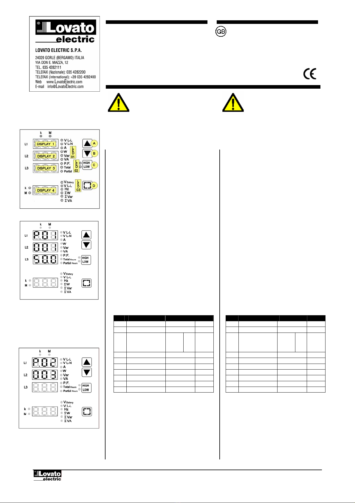
Przykład ustawiania przekładni
150 (750 / 5).
Example of CT ratio set to 150
(750 / 5).
Przykład ustawiania filtru uśredniania
na wartość 3.
Example of average filter 3 setting
OPIS
•Zasilanie baterii 9…32VDC. Przeznaczony do
zastosowania w aplikacjach z generatorem. Odporny
na wahania napięcia (odporność na mikrowyłączenia
500 ms)
•4 wyświetlacze LED o wysokiej dokładności.
•Łatwy do montażu i konfiguracji.
•Pomiar RMS (TRMS).
•47 pomiary i funkcja analizatora sieci
•Zapis wartości max i min.
•Zakres pomiaru napięcia baterii 9…38VDC.
USTAWIENIA PARAMETRÓW
•Naciśnij jednocześnie przyciski C i D przez 5 sekund
by uzyskaćdostęp do ustawień
•Wyświetlacz DISPLAY 1 pokaże P.01 co oznacza że
wybrany do ustawiania zostałparametr 01.
•Wyświetlacz DISPLAY 2 i 3 pokaże wartość
zaprogramowanądla wybranego parametru.
•Przyciskami A i B zwiększamy lub zmniejszamy
wartość wybranego parametru.
•Przyciskami C i D wybieramy param. P.01 do P.10.
•Naciskając przycisk D przez 2 sekundy
zapamiętujemy ustawienia i wychodzimy.
•Normalnie, by urządzenie zaczęło działać, ustawiamy
tylko parametr P.01, pozostałe zostawiamy jako
domyślne, ustawione fabrycznie
TABELA PARAMETRÓW
PAR Funkcja Zakres Domyśl
P.01 Przekładnia CT 1.0 ÷ 2000 1.0
P.02 Filtr uśredniania 1÷ 5 3
P.03 Typ połączeń1 f
2 f
3 f
3 f.sym
1ph
2ph
3ph
3bl
3ph
P.04 Częstotliwość Aut – 50 – 60 Aut
P.05 Wst. ust. wyś1-2-3 1÷9 1
P.06 Wst. ust. wyś4 1÷6 1
P.07 Ust. opóźnienie Off÷250 sec 60
P.08 Próg napięcia 0ff÷100.0 Off
P.09 Próg prądu 0ff÷100.0 Off
P.10 Ust. liczba godzin Off÷60000 Off
Uwaga! Miernik może mierzyćmoce do wartości
40MVA .
•By ustawićwartość parametru P.01 na 5-cyfr ±0,1
użyj razem wyświetlaczy 2 i 3.
•P.02 pozwala zmienićefekt stabilizacji funkcji
uśredniania używanej do pomiarów
•P.03 musi odpowiadaćpodłączeniom miernika,
zobacz “Schematy połączeń”.
W układzie trójfazowym symetrycznym, tylko jeden
CT musi byćpodłączony do fazy L1.
Wyłączając wartości napięcia, wszystkie inne
pomiary na fazach L2 i L3 sątakie same jak na L1.
DESCRIPTON
•Battery power supply 9…32VDC. Designed to meet the
technical requirements of generating-set applications.
Able to survive during cranking dropouts (500ms micro-
breaking immunity)
•4 LED displays for excellent readability.
•Easy to install and configure.
•Measurements in the RMS (TRMS).
•47 measurements with power analyser functions.
•Maximum and minimum measurement recording.
•Battery (supply) voltage measurement range 9…38VDC.
PARAMETER SETTING
•Press keys C and D together for 5 seconds to access
setting.
•DISPLAY 1 will show P.01 meaning that the setting for
parameter 01 has been chosen.
•DISPLAY 2 and 3 will show the current value of
parameter
•Key A and B increase \ decrease the value of the
currently selected parameter.
•Key C and D select parameter from P01 to P.10.
•Press key D for 2 seconds to store the setting and exit.
•Normally , to set the instrument working it is necessary
to set parameter P0.1 only, leaving the other parameters
at the default value.
PARAMETER TABLE
PAR Function Range Default
P.01 CT ratio 1.0 ÷ 2000 1.0
P.02 Average filter 1÷ 5 3
P.03 Type of connection 1 fase
2 fasi
3 fasi
3 fasi bil.
1ph
2ph
3ph
3bl
3ph
P.04 Frequency Aut – 50 – 60 Aut
P.05 Preset display 1-2-3 1÷9 1
P.06 Preset display 4 1÷6 1
P.07 Preset delay Off÷250 sec 60
P.08 Voltage threshold 0ff÷100.0 Off
P.09 Current threshold 0ff÷100.0 Off
P.10 Partial preset Off÷60000 Off
Note! The DMK calculating system can handle total power
values of up 40 MVA.
•To set the value of parameter P0.1 DISPLAYS 2 and 3
are use together to view and value with 5 digit +1 decimal.
•P.02 allows to change the stabilising effect to the
average function applies to the measurements.
•P.03 mast reflect the multimeter connection ( see the
“wring diagrams” section).
Whit balanced three – phase connection only one CT is to
be inserted on phase L1.
Except for voltage values, all the other measurements on
phase L2,L3 are the same as phase L1.
I144 PL GB 09 03
WARNING! This equipment is to be installed by
trained personnel, complying to current standard,
to avoid damages or safety hazards. Products
illustrated herein are subject to alteration and
changes without prior notice. Technical data and
descriptions in the documentation are accurate, to
the best of our knowledge, but no liabilities for
errors, omossions or contingencies arising
therefrom are accepted.
UWAGA!!
Aby uniknąć zagrożenia dla zdrowia
i życia oraz uszkodzenia sprzętu, urządzenie
powinno byćinstalowane z zastosowaniem
obowiązujących norm przez wykwalifikowany
personel. Przedstawiany tu produkt może byćw
każdej chwili zmodyfikowany. Dane techniczne
oraz część opisowa oddająw jak najdokładniejszy
sposób posiadanąprzez nas wiedzę, jednak nie
bierzemy odpowiedzialności za ewentualne błędy,
braki oraz sytuacje awaryjne.
I144 PL GB 09 03 P 1 / 6
I144 PL GB 09 03 P 2 / 6
•P.04 ustawiamy 50 lub 60 Hz, odświeżanie jest
częstsze. Zobacz Dane Techniczne
•P.05 i P.06 sąużywane do ustawiania jakie pomiary
sądomyślne na wyświetlaczach 1-2-3–4.
P.05 Pomiar P.06 Pomiar
1 V L-L 1 V Baterii
2 V L-N 2 V L-L
3 A 3 Hz
4 W 4 ΣW
5 var 5 Σvar
6 VA 6 ΣVA
7 P.F.
8 Całkow. godziny
9 Częściowe godz.
•P.07 jest używany do ustalania czasu kasowania
konfiguracji zrobionej z P.05 i P.06.
•P.08 e P.09 wyrażająodpowiednio progi procentowe
napięcia i prądu (odnośnie do zakresu pomiaru)
by synchronizowaćstart licznika całkowitego z
częściowym. Jeśli oba parametry zostału ustawione
na OFF, liczniki startująkiedy urządzenie jest zasilone.
•P.10 jest używany do ustawienia liczby godzin, od
których licznik, bedzie zmniejszałsie do zera. Kiedy
zostanie osiągnięte zero, licznik zacznie zliczać
wartości ujemne (miga dioda PARTIAL).
WYŚWIETLANIE POMIARÓW
Funkcje przycisków A i B
•Przyciski A i B służą do wyboru pomiarów
pokazanych w grupie LED01.
•Pomiary odpowiadające fazom L1, L2 i L3 sąna
wyświetlaczach 1, 2 i 3.
•Diody LED ki Mpokazująże pomiary sąwyrażone
w tysiącach lub milionach.
TABELA POMIARÓW GRUPY LED 01:
LED Funzione
V L-L Napięcie międzyfazowe
V L-N Napięcie fazowe
A Prąd
W Moc aktywna
var Moc bierna
VA Moc pozorna
P.F. Całkowity współczynnik mocy
(T.P.F , Total Power Factor)
Całkow godz. Calkowita ilość godzin
Część. godz.
Częściowa ilośćgodzin
•W układzie bez przewodu neutralnego, wyświetla się
wewnętrzne napięcie DMK w układzie gwiazdy
•Całkowity współczynnik mocy jest obliczany z
uwzględnieniem odkształceńharmonicznych prądu
i napięcia
•Wyświetlacze 1-2-3 w odpowiedniej kolejności,
pokazuje napięcia międzyfazowe L1-L2,L2-L3 i L3-
L1.
•Wyświetlacz godzin jest wyrażony w godzinach
i minutach oddzielonych kropką(Np. 1500.30 to 1500
godzin i 30 minut). Mrugająca kropkaoznacza iżlicznik
działa.
KASOWANIE LICZNIKA GODZIN (Partial hours)
•Używając przycisków A lub B, przesunąć sięna
pomiar Partial hours bez zwalniania przycisku kiedy
dany pomiar jest ustawiony i nacisnąć przycisk D
•Przytrzymując wciśnięte przez 5 sekund, kasujemy
wartość wybranego parametru.
•Na wyświetlaczach pokaże sięskrót CLr (cleared)
potwierdzający operację.
•Whit P.04 set at 50 or 60 Hz, viewing is refreshed more
often.
•P.05 and p.06 are used to establish which default
measurement to view on DISPLAYS 1-2-3-4.
P.05 Misura P.06 Misura
1 V L-L 1 V Battery
2 V L-N 2 V L-L
3 A 3 Hz
4 W 4 ΣW
5 var 5 Σvar
6 VA 6 ΣVA
7 P.F.
8 Total hours
9 Partial hours
•P.07 is used to the reset time of configuration made with
configuration made with P.05 and P.06.
•P.08 and P.09 are respectively the voltage phase and
current thresholds expressed in percentage (referred to
the measurements range), to synchronize the start of the
total and partial hour meters. If both parameters have
been set at OFF the hour counters are started when the
instrument is powered.
•P.10 is used to set a number of partial of hours that will
be decreased down to zero. Once zero has been reached
the counter continues to decrease negatively (partial LED
flashing).
VIEWING THE MEASURAMENTS
Keys A and B functions
•Keys A and B are used to select the measurement
indicated by LED 01 group.
•The measures related with phases L1,L2 and L3 are
show respectively on DISPLAY 1, 2 and 3.
•LEDs kand Mat the top respectively indicate that
measurements are expressed in thousands or millions.
LED 01 GROUP MEASURAMENT TABLE:
LED FUNCTION
V L-L Line voltage
V L-N Phase voltage
A Current
W Active power
var Reactive power
VA Apparents power
P.F. Total power factor
(T.P.F , Total Power Factor)
Total hours
Total hours
Partial hours
Partila hours
•without the neutral connection , the DMK internal star
voltage is shown.
•Total power factor calculated taking into consideration
the voltage and current harmonic distortion.
•DISPLAYS 1-2-3 respectively view line voltages L1-L2,
L2- L3 and L3-L1.
•The partial hour current display is in hours and minutes
separated by a dot (E.g.1500.30 means 1500 hours and
30 minutes).The flashing dot means that the partial hour
counter is working.
PARTIAL HOUR METER CLEARING
•Using key A or B move to the Partial Hours
measurement without releasing the key once the required
measurement has been reached.
•keeping it pressed for 5 consecutive seconds, the value
of the chosen measurement is cleared.
•The wording CLr (cleared) is shown on the display to
confirm it has taken place.
I144 PL GB 09 03 P 3 / 6
KASOWANIE LICZNIKA GODZIN (Total hours)
•Używając przycisków A lub B, przesunąć sięna
pomiar Total hours bez zwalniania przycisku kiedy
dany pomiar jest ustawiony i nacisnąć przycisk D
•Przytrzymując wciśnięte przez 5 sekund, kasujemy
wartość wybranego parametru.
•Na wyświetlaczach pokaże sięskrót CLr (cleared)
potwierdzający operację.
FUNKCJA PRZYCISKU C
Przycisk C jest używany do załączania jednej z funkcji
z grupy LED 02, lub wyłączenia wszystkich
DIODY LED HIGH I LOW
Na odpowiednim wyświetlaczu pokazane sązapisane
wartości max i min dla następujących pomiarów:
WYŚW. Pomiar Funkcja
1-2-3 V L-N Napięcie fazowe
1-2-3 A Prąd
4 ΣW Moc czynna
4 Σvar Moc bierna
4 ΣVA Moc pozorna
Uwaga: Wartości max sązapamiętywane przy zaniku
napięcia zasilania
KASOWANIE WARTOŚCI HIGH I LOW
•Używając przycisku C, przejdźdo funkcji (High
Low) bez zwalniania przycisku kiedy dany pomiar
jest ustawiony
•Przytrzymując wciśnięte przez 5 sekund, kasujemy
wartość wybranego parametru.
•Na wyświetlaczach pokaże sięskrót CLr (cleared)
potwierdzający operację.
•Wszystkie pomiary dostępne sąkasowane
•Kasowanie uwzględnia zapis pomiarów chwilowych
max i min
FUNKCJE PRZYCISKU D
•Używając przycisku D, możemy wybieraćjedną
z pośród sześciu funkcji z grupy LED 03 i zobaczyć
je na wyświetlaczu nr 4
•Te pomiary sąśredniąz trzech faz. Dla jednostki
pomiaru, wyświetlacz nr 4 ma swoje własne diody
ki M (lewa strona panelu)
LED Funkcja
V Battery Pomiar napięcia baterii
V L-L Średnie napięcie linii
Hz Częstotliwość
ΣW Całkowita moc czynna
Σvar Całkowita moc bierna
ΣVA Całkowita moc pozorna
TOTAL HOUR METTER CLEARING
•Using key A or B move to the Total Hours
measurement without releasing the key once the required
measurement has been reached and press key D.
•keeping it pressed for 5 consecutive seconds, the value
of the chosen measurement is reset.
•The wording CLr is shown on the display to confirm it
has taken place.
KEY C FUNCTION
Key C is used to enable one of the functions contained in
LED 02 group, or leave them all disabled.
HIGH AND LOW LEDs.
These respectively display instantaneous maximum and
minimum values recorded by the instrument for the
following measurements:
DISPLAY Misura Funzione
1-2-3 V L-N Phase voltage
1-2-3 A Current
4 ΣW Active power
4 Σvar IReactive power
4 ΣVA Apparent power
Note: The high values are also stored at the lack of
supply voltage.
HIGH\LOW VALUE CLEARING
•Using key C, move to the function (High Low) without
releasing the key once the required function has been
reached.
•Keeping it pressed for 5 consecutive seconds, the
values the function chosen are cleared.
•The wording CLr (cleared) is shown on the display to
confirm it has taken place.
•All the measurement available with the function are
cleared.
•Clearing consists of recording the measurement
in that moment as maximum or minimum value.
KEY D FUNCTIONS
•Using key D, it is possible to select among the six
functions of LED group 03 and view them on DISPLAY 4.
•These measurements are to be intended as the average
of the three phases. For the unit of the measure, DISPLAY
4 has its own kand MLEDs on the left.
LED Function
V Battery Battery voltage measure
V L-L Line voltage averange
Hz Frequency
ΣW Total active power
Σvar Total reactive power
ΣVA Total apparent power
SCHEMATY POŁĄCZEŃ
I144 PL GB 09 03 P 4 / 6
CI3I2
CURRENT
I1NL3L1 L2
VOLTAGE
L
O
A
TA2
TA1
D
L1
L3
L2
12...24VDC
BATTERY
-
AUX SUPPLY
+
Obwód trójfazowy bez przewodu neutralnego
Pomiar prądu w układzie Arona
Parametr P.03 = 3ph (domyślne ustawienia
fabryczne)
Three-phase without neutral
Current input with Aron wiring configuration
Parameter P.03 set to 3ph (default factory setting)
WIRING DIAGRAMS
WAŻNA UWAGA O POMIARZE W UKŁADZIE ARONA
Ta konfiguracja zwiększa dokładność pomiaru wartości prądu fazowego bez CT, od ±0,25% zakresu ±1cyfra do ±0,75% zakresu ±1cyfra
IMPORTANT NOTE ABOUT ARON WIRING CONFIGURATION
This configuration increases the accuracy value of the phase current measurement without CT, from ±0,25% full scale ±1digit to ±0,75% full scale ±1digit.
Notka:TA = Przekładnik prądowy Note: CT = Current transformer.
TV = Przekładnik napięciowy VT = Voltage transformer.
N
L2
L3
L1
CURRENT
VOLTAGE
L2L1L3NI1I2I3C
TA2
TA1
TA3 O
A
D
L
AUX SUPPLY
-+
BATTERY
12...24VDC
Obwód trójfazowy z przewodem neutralnym
Parametr P.03 = 3ph (domyślne ustawienia
fabryczne)
Three-phase with neutral
Parameter P.03 set to 3ph (default factory setting)
VOLTAGE
L2L1 NL3
L2
L3
L1
CURRENT
I1 I2 I3 C
TA2
TA1
TA3 O
D
A
L
12...24VDC
BATTERY
-
AUX SUPPLY
+
Obwód trójfazowy bez przewodu neutralnego
Parametr P.03 = 3ph (domyślne ustawienia
fabryczne)
Three-phase without neutral
Parameter P.03 set to 3ph (default factory setting)
TA1
VOLTAGE
N
L2
L1 L2 NL3 I1
L1
CURRENT
O
TA2
I2 I3 C
A
D
L
12...24VDC
BATTERY
-
AUX SUPPLY
+
Obwód dwufazowy
Parametr P.03 = 2ph
Two-phase
Parameter P.03 set to 2ph
12...24VDC
BATTERY
-
AUX SUPPLY
+
VOLTAGE CURRENT
C
N
L
L2L1 L3 I2I1NI3
TA1
A
D
L
O
Obwód jednofazowy
Parametr P.03 = 1ph
Single-phase
Parameter P.03 set to 1ph
VOLTAGE
L3
L2
AUX SUPPLY
L3
+
-L2L1
BATTERY
12...24VDC
L1
A
CURRENT
NI1 I2 I3 C
D
TA1
TA3
L
O
Obwód trójfazowy bez przewodu neutralnego
Pomiar prądu w układzie Arona
Parametr P.03 = 3ph (domyślne ustawienia
fabryczne)
Three-phase without neutral
Current input with Aron wiring configuration
Parameter P.03 set to 3ph (default factory setting)
I144 PL GB 09 03 P 5 / 6
Charakterystyka techniczna
Zasilanie Ausiliari supply
Napięcie znamionowe (Us) 12 – 24VDC
z baterii
Rated voltages (Us) 12 – 24VDC
by battery
Zakres pracy 9…32VDC Operation limits 9 -32VDC
Pobór maksymalny 1,1W Maximum consumption 1.1W
Rozproszenie maksymalne 1,1W Maximum dissipation 1.1W
Odporność na mikrowyłaczenia 500ms Immunity time at micro breaking 500ms
Wejścia napięciowe Voltage inputs
Max. Napięcie znamionowe (Ue) 690VAC L-L (400VAC L-N) Max. rated voltage Ue 690VAC phase-phase (400VAC phase
neutral)
Wg UL 600VAC L-L 347VAC L-N UL rating 600VAC phase-phase 374VAC phase-
neutral
Zakres częstotliwości 45…65Hz Frequency range 45 - 65Hz
Typ pomiaru True RMS Measuring method True RMS
Impedancja wejścia pomiarowego >1,1MΩL-L i >570KΩL-N Measuring input impedance >1.1MΩphase-phase and >570KΩ
phase-neutral
Typ połaczenia Jedno, dwu , trójfazowe i symetryczne
trójfazowe
Wiring mode Single-phase, two phase, tree phase and
balanced three phase.
Wejścia prądowe Current inputs
Prąd znamionowy (Ie) 5A (1A na życzenie) Rated current Ie 5A (1A on request)
Zakres pomiaru 0,05…6A Measuring range 0.05 - 6A
Typ wejścia Zewnętrzny przekładnik prądowy Input type Internal insulated CT
Wg UL Przez zewnętrzny przekładnik prądowy
(niskie napięcie) max 5A
UL rating Supplied by an external CT
( low voltage) max 5A
Typ pomiaru True RMS
Measuring method True RMS
Przeciążenie +20% Ie przez zewnętrzny przekładnik
prądowy 5A
Overload capacity +20% Ie from external CT with 5A
secondary
Pik przeciążenia 50A przez 1 sekunde Overload peak 50A for 1 seconds
Graniczny prąd dynamiczny 125A przez10ms Dynamic limit 125A for 10ms
Pobór własny mocy <0,2VA per fase Self - consumption <0.2VA for phase
Dokładność pomiaru Measuring accuracy
Warunki pomiaru Measuring conditions
Temperatura
Względna wilgotność
Napięcie DC
Napięcie
Prąd
+23°C ±1°C
45±15%
9 - 32VDC (Us)
0,2 - 1.2 Ue
0,2 - 1.2 Ie
Temperature
Relative Humidity
DC Voltage
Voltage
Current
+23°C ±1°C
45±15%
9 - 32VDC (Us)
0.2 - 1.2 Ue
0.2 - 1.2 Ie
Napięcie DC Klasa 0.5
±0.25% pełnej skali ±1 cyfra
DC Voltage Class 0.5
±0.25% full scale. ±1digit
Napięcie Klasa 0,5
±0,25% pełnej skali ±1 cyfra
Voltage Class 0.5
±0.25% full scale. ±1digit
Prąd Klasa 0,5
±0,25% pełnej skali ±1 cyfra
Current Class 0.5
±0.25% full scale. ±1digit
Częstotliwość ±1 cyfra Frequency ±1digit
Moc pozorna ±0,5% pełnej skali ±1 cyfra Apparent power ±0.5% full scale ±1digi
±1% pełnej skali ±1 cyfra
(cosϕ. 0,7 ÷1)
±1% f.s. ±1digit
(cosϕ. 0.7 - 1)
Moc czynna
±1,25% pełnej skali ±1 cyfra
(cosϕ. 0,3 ÷0,7)
Active power
±1.25% f.s. ±1digit
(cosϕ. 0.3 – 0.7)
±1% pełnej skali ±1 cyfra
(sinϕ. 0,7 ÷1)
±1% f.s. ±1digit
(senϕ. 0.7 – 1)
Moc bierna
±1,25% pełnej skali ±1 cyfra
(sinϕ. 0.3 – 0.7)
Reactive power
±1% f.s. ±1digit
(senϕ. 0.3 – 0.7)
Dodatkowe błędy Additional errors
Względna wilgotność ±1 cyfra 60% - 90% R.H. Relative Humidity ±1digit 60% to 90% R.H.
Temperatura ±1 cyfra –20° ... +60°C Temperature ±1digit –20° to +60°C
Izolacja Insulation
Nominalne napięcie izolacji (Ui)
IEC/EN 61010-1
690V Nominal insulation voltage (Ui)
IEC/EN 61010-1
690V
Warunki pracy Ambient operating conditions
Temperatura pracy -20…+60°C Operating temperature -20 to +60°C
Temperatura składowania -30…+80°C Storage temperature -30 to +80°C
Względna wilgotność <90% Relative Humidity <90%
Max stopieńzanieczyszczenia stopień2 Max pollution degree 2
Połączenie Connections
Typ zacisków Wtykowe Terminal type Plug - in
Przekrój kabla (min i max) 0,2…2,5 mmq (24÷12 AWG) Cable cross selection (min - max) 0.2 - 2,5 mmq (24 - 12 AWG)
Moment dokręcenia 0,5 Nm (4,5 LBin) Tigheting torque 0.5 Nm (4.5 LBin)
Obudowa Housing
MateriałNoryl SE1-GNF2 czarny, samogasnący Material N190 blak Self-extinguishing Noryl
Wersja Tablicowa, zgodna z IEC61554 Version Flush mount for IEC 61554
Wymiary SZ x W x G 96 x 96 x 76mm Dimension w x h x d 96 x 96 x 76 mm
Wycięcie w panelu 91 x 91mm Cutout 91 x 91 mm
Stopieńochrony IP54 od przodu
IP54 z pokrywąochronną
IP20 zaciski
Degree of protection IP54 frontal
IP54 with transparent cover
IP20 housing and terminals
Masa 350g Weihgt 350g
Certyfikaty i normy Compllance
Normy IEC/EN 61010-1:2001 - IEC/EN 61000-6-
2:1999 - CISPR 11/EN 55011:1998+ A1
EC/EN 61000-3-2:1995 + A12 + A1 + A2+ EC
+ A14
IEC/EN 61000-3-3:1995 + A1 - IEC/EN
60068-2-61:1993
IEC/EN60068-2-27:1993 - IEC/EN60068-2-
6:1995 - UL508 - C22.2-N°14-95
Reference standards IEC/EN 61010-1:2001 - IEC/EN 61000-6-
2:1999 - CISPR 11/EN 55011:1998+ A1
EC/EN 61000-3-2:1995 + A12 + A1 +
A2+ EC + A14
IEC/EN 61000-3-3:1995 + A1 - IEC/EN
60068-2-61:1993
IEC/EN60068-2-27:1993 - IEC/EN60068-
2-6:1995 - UL508 - C22.2-N°14-95
UL “marking” UL “marking”
•Te urządzenia powinny byćchronione bezpiecznikami 15A na wejściu
napięciowym.
•Użyj przewodnika miedzianego (CU) 60°C/75°C o zakresie 18/12 AWG,
linka lub drut
•Montażna płaszczyźnie w obudowie "Type 1"
These Devices shall be protected by Any Listed Fuses, Miscellaneous,
Miniature and Micro (JDYX) 15 A Fuses on voltage input phases
"Use 60°C/75°C copper (CU) conductor and wire size range 18-12
AWG, stranded or solid"
“For use on a flat surface of a Type 1 Enclosure”
Wymiary (mm) Overall dimensions and panel cutout
I144 PL GB 09 03 P 6 / 6
- Instalacja urządzenia wymaga przełącznika albo automatycznego wyłącznika.
- Musi byćon zainstalowany blisko urządzenia, aby byłłatwo dostępny dla
operatora.
- Musi byćoznaczony jako urządzenie: IEC/EN 61010-§ 6.12.2.1.
-A load–break switch or circuit breaker must be included in the electrical
installation of the building.
-It must be installed close by the equipment and within easy reach of the
operator.
-It must be marked the disconnecting device of the equipment:
IEC /EN 61010-1 § 6.12.2.1

Other LOVATO ELECTRIC Multimeter manuals

LOVATO ELECTRIC DMG800 User manual

LOVATO ELECTRIC

LOVATO ELECTRIC DMG800 User manual

LOVATO ELECTRIC DMG600 User manual

LOVATO ELECTRIC

LOVATO ELECTRIC DMG600 User manual

LOVATO ELECTRIC DMK 61 User manual

LOVATO ELECTRIC

LOVATO ELECTRIC DMK 61 User manual

LOVATO ELECTRIC DMG100 User manual

LOVATO ELECTRIC

LOVATO ELECTRIC DMG100 User manual

LOVATO ELECTRIC DMG800L01 User manual

LOVATO ELECTRIC

LOVATO ELECTRIC DMG800L01 User manual

LOVATO ELECTRIC DMG210L01 User manual

LOVATO ELECTRIC

LOVATO ELECTRIC DMG210L01 User manual

LOVATO ELECTRIC DMG611R Series User manual

LOVATO ELECTRIC

LOVATO ELECTRIC DMG611R Series User manual

LOVATO ELECTRIC DMG210 User manual

LOVATO ELECTRIC

LOVATO ELECTRIC DMG210 User manual

LOVATO ELECTRIC DMG600 User manual

LOVATO ELECTRIC

LOVATO ELECTRIC DMG600 User manual

LOVATO ELECTRIC DMK 20 User manual

LOVATO ELECTRIC

LOVATO ELECTRIC DMK 20 User manual

LOVATO ELECTRIC DMK 21 User manual

LOVATO ELECTRIC

LOVATO ELECTRIC DMK 21 User manual

LOVATO ELECTRIC DMG300 User manual

LOVATO ELECTRIC

LOVATO ELECTRIC DMG300 User manual

LOVATO ELECTRIC DMG800RGCA User manual

LOVATO ELECTRIC

LOVATO ELECTRIC DMG800RGCA User manual

LOVATO ELECTRIC DMG610 User manual

LOVATO ELECTRIC

LOVATO ELECTRIC DMG610 User manual

LOVATO ELECTRIC DMG615 User manual

LOVATO ELECTRIC

LOVATO ELECTRIC DMG615 User manual

LOVATO ELECTRIC DMG600 User manual

LOVATO ELECTRIC

LOVATO ELECTRIC DMG600 User manual

LOVATO ELECTRIC DMG610 User manual

LOVATO ELECTRIC

LOVATO ELECTRIC DMG610 User manual

LOVATO ELECTRIC DMK16 User manual

LOVATO ELECTRIC

LOVATO ELECTRIC DMK16 User manual

LOVATO ELECTRIC DMG800 User manual

LOVATO ELECTRIC

LOVATO ELECTRIC DMG800 User manual

LOVATO ELECTRIC DMG600 User manual

LOVATO ELECTRIC

LOVATO ELECTRIC DMG600 User manual

LOVATO ELECTRIC DMG600 User manual

LOVATO ELECTRIC

LOVATO ELECTRIC DMG600 User manual

LOVATO ELECTRIC DMG600 User manual

LOVATO ELECTRIC

LOVATO ELECTRIC DMG600 User manual

LOVATO ELECTRIC DMG300 L01 User manual

LOVATO ELECTRIC

LOVATO ELECTRIC DMG300 L01 User manual

LOVATO ELECTRIC DMG200 User manual

LOVATO ELECTRIC

LOVATO ELECTRIC DMG200 User manual

Popular Multimeter manuals by other brands

FLIR IM75-2 user manual

FLIR

FLIR IM75-2 user manual

Amprobe AC71B user manual

Amprobe

Amprobe AC71B user manual

Extech Instruments MN30 user manual

Extech Instruments

Extech Instruments MN30 user manual

Extech Instruments 380947 user guide

Extech Instruments

Extech Instruments 380947 user guide

VOLTCRAFT 12 44 55 VC135 operating instructions

VOLTCRAFT

VOLTCRAFT 12 44 55 VC135 operating instructions

MARTINDALE MM37 instructions

MARTINDALE

MARTINDALE MM37 instructions

Shijiazhuang Suin Instruments Co., Ltd SA5041 user guide

Shijiazhuang Suin Instruments Co., Ltd

Shijiazhuang Suin Instruments Co., Ltd SA5041 user guide

Testboy TB 312 operating instructions

Testboy

Testboy TB 312 operating instructions

Keysight U1233A user guide

Keysight

Keysight U1233A user guide

Draper DMM17 Instructions for

Draper

Draper DMM17 Instructions for

Harbor Freight Tools 40994 operating instructions

Harbor Freight Tools

Harbor Freight Tools 40994 operating instructions

Craftsman 82312 owner's manual

Craftsman

Craftsman 82312 owner's manual

Fluke 8506A instruction manual

Fluke

Fluke 8506A instruction manual

Elma BM126 user manual

Elma

Elma BM126 user manual

PeakTech 1080 Operation manual

PeakTech

PeakTech 1080 Operation manual

IDEAL 61-494 Technical manual

IDEAL

IDEAL 61-494 Technical manual

Würth MM 50/20 Translation of the original operating instructions

Würth

Würth MM 50/20 Translation of the original operating instructions

Mastech MS8239A user manual

Mastech

Mastech MS8239A user manual

manuals.online logo
manuals.online logoBrands
  • About & Mission
  • Contact us
  • Privacy Policy
  • Terms and Conditions

Copyright 2025 Manuals.Online. All Rights Reserved.