manuals.online logo
Brands
  1. Home
  2. •
  3. Brands
  4. •
  5. LOVATO ELECTRIC
  6. •
  7. Relay
  8. •
  9. LOVATO ELECTRIC LVM25 User manual

LOVATO ELECTRIC LVM25 User manual

I223PLGB_0307 03/2007 Str. 1/ 3
PL
PRZEKAŹNIK POZIOMU LEVEL RELAY
DLA PŁYNÓW FOR CONDUCTIVE LIQUIDS
PRZEWODZĄCYCH
LVM25
OPIS
- Kontrola poziomu plynów przewodzących
- Detekcja 3 elektrodowa COM, MIN i MAX
(sondy sprzedawane osobno)
- Regulacja czułości 2,5 ... 100 kΩ
- Funkcja napełniania (UP) i opróżniania
(DOWN)
- Zasilanie AC/DC
- Zielona dioda LED sygnalizująca zasilanie
- Czerwona dioda LED sygnalizująca stan
pompy
- Wejścia elektrod zabezpieczone
warystorami
DZIAŁANIE
LVM25 jest przekaźnikiem kontroli poziomu
do płynów przewodzących, umożliwia
kontrolęnapełniania lub opróżniania
zbiornika, poprzez odpowiednie ustawienie
potencjometru MODE, za pomocąelektrod
MIN i MAX. Czułość przekaźnika jest
regulowana w zakresie od 2.5 do 100kΩ.
FUNKCJA OPRÓŻNIANIA „DOWN”
Z UŻYCIEM 3 SOND
Gdy poziom cieczy osiągnie MAX,
przekaźnik jest pobudzony i aktywuje pompę
opróżniania zbiornika lub studni. Gdy poziom
cieczy jest niższy od MIN, przekaźnik
przechodzi w stan nie-pobudzenia i wyłącza
pompę.
Przekaźnik jest załączany gdy poziom płynu
jest wyższy od MAX, ale tylko jeśli elektroda
MIN jest zanurzona w płynie przewodzącym.
FUNKCJA NAPEŁNIANIA „UP”
Z UŻYCIEM 3 SOND
Kiedy poziom cieczy jest wyższy niżsonda
MIN, wyjście przekaźnika, który kontroluje
pompęnapełniania zbiornika jest pobudzone.
Kiedy poziom płynu osiągnie MAX pompa
jest zatrzymywana.
FUNKCJA OPRÓŻNIANIA „DOWN”
Z UŻYCIEM 2 SOND.
Ten typ działania wymaga podłączenia
zacisku MAX z zaciskiem COM .
Gdy poziom cieczy osiągnie MIN, przekaźnik
wyjściowy jest załączany i aktywuje pompę
opróżniającązbiornik. Gdy poziom cieczy
jest jużniższy od MIN, wyjście przekaźnika
przechodzi w stan nie-pobudzenia i pompa
jest zatrzymywana. Minimalny czas przerwy
pomiędzy rozruchem a zatrzymaniem
DESCRIPTION
– Level control for conductive liquids
– Detection by means of electrodes COM,
MIN and MAX, to be purchased separately
– Sensitivity adjustment 2.5...100kΩ
– Filling (UP) and emptying (DOWN)
function
– AC/DC supply voltage
– Indication LED for power ON
– Indication LED for pump relay status
– Electrode input protected by varistors.
OPERATION
LVM25 is a level control relay for conductive
liquids, which provides the tank emptying or
filling control, by rotating the MODE selector,
by means of MIN and MAX level electrodes.
With the “Sensitivity” potentiometer, the
adjustment of the relay sensitivity, between
2.5 and 100kΩ, is obtained.
EMPTYING “DOWN” FUNCTION USING 3
ELECTRODES
When the liquid reaches, the MAX electrode,
the output relay energises and switches on
the tank or well-emptying pump. When the
liquid does not wet the MIN electrode, the
output relay de-energises and switches off
the pump.
The level relay energises when the liquid
wets the MAX electrode but only if the MIN
electrode is wet by the liquid as well.
FILLING “UP” FUNCTION USING 3
ELECTRODES
When the liquid wets the MIN electrode, the
output relay, which controls the tank-filling
pump, energises. When the liquid wets the
MAX electrode, the pump is stopped.
EMPTYING “DOWN” FUNCTION USING 2
ELECTRODES
This type of operation requires the MAX
terminal to be shorted on the COM terminal.
When the liquid wets the MIN electrode, the
output relay energises and switches on the
tank-emptying pump. When the liquid no
longer wets the MIN electrode, the output
relay de-energises and switches off the
pump. The minimum time interval between
pump starting and stopping is about 1 second,
I223
PL
GB 0
307
CAUTION! This equipment must
be installed by qualified personnel,
complying with current standards,
to avoid damages or safety hazards.
UWAGA! W celu uniknięcia uszkodzeń
i zagrożenia urządzenia te musząbyć
instalowane przez wykwalifikowany
personel, zgodnie z obowiązującymi
standardami.
Products illustrated herein are subject to alterations
and changes without prior notice. Technical data and
descriptions in the documentation are accurate to the
best of our knowledge, but no liabilities for errors,
omissions, or contingencies arising therefrom are
accepted.
Produkty zaprezentowane w tym dokumencie są
zgodne z nasząaktualnąofertą, ale zastrzegamy
sobie prawo do wprowadzenia zmian bez
wcześniejszego powiadomienia. Dane i opisy
wyszczególnione w tym dokumencie nie mają
wartości kontraktowej, więc nie odpowiadamy za
powstałe błędy lub pominięcia.
I223PLGB_0307 03/2007 Str. 2/ 3
wynosi około 1 sekundy, to jest czas
opóźnienia sondy.
FUNKCJA NAPEŁNIANIA „UP”
Z UŻYCIEM 2 SOND
Ten typ pracy nie wymaga podłączenia
sondy MIN
Gdy poziom cieczy osiągnie MAX,
przekaźnik wyjściowy jest załączany,
i aktywuje pompęnapełniającązbiornik.
Gdy poziom cieczy jest niższy niżMAX,
pompa jest ponownie załączana.
Minimalny czas przerwy pomiędzy
rozruchem a zatrzymaniem wynosi około
1 sekundy, to jest czas opóźnienia sondy.
UWAGA
Do aplikacji z wodą, czułość standardowo
ustawiana jest na poziomie 6-8 kΩ. Dla
płynów o mniejszej przewodności, jak
deszczówka, czułość może byćustawiona aż
do 100kΩ. Zaleca sięumieszczanie
przewodów elektrod z dala od linii
zasilających
i.e. probe filter time.
FILLING “UP” FUNCTION USING 2
ELECTRODES
This type of operation does not require any
MIN probe.
When the liquid wets the MAX electrode, the
output relay, which controls the tank-filling
pump, de-energises. When the liquid no
longer wets the MAX electrode, the pump is
restarted.
The minimum time interval between pump
starting and stopping is about 1 second, i.e.
probe filter time.
NOTE
For water level control applications, the
sensitivity is normally adjusted to 6-8kΩ.
For less conductive liquids, like rain water,
the sensitivity can be increased up to 100kΩ.
It is recommended to keep the probe cables
separated from the power lines.
I223PLGB_0307 03/2007 Str. 3/ 3
Schematy połączeń
Wymiary
Funkcje działania
FUNKCJA OPRÓŻNIANIA „DOWN”
Z UŻYCIEM 3 SOND
FUNKCJA NAPEŁNIANIA
„UP” Z UŻYCIEM 3 SOND
FUNKCJA OPRÓŻNIANIA „DOWN”
Z UŻYCIEM 2 SOND.
FUNKCJA NAPEŁNIANIA „UP”
Z UŻYCIEM 2 SOND
DANE TECHNICZNE
Zasilanie i kontrola
Napięcie znamionowe Ue 24…240VAC/DC
Czestotliwość znamionowa 50/60Hz ±5%
Zakres działania 0,85…1,1 Ue
Pobór mocy 3,0VA max
Rozproszenie mocy 1,2W max
Sondy poziomu
Napięcie elektrod
7,5VAC
Prądpłynący przez elektrode 0,4mA max
Max długość kabla ( Nota 1) 800m max / czułość 25 k
400m max / czułość 50 k
200m max / czułość 100 k
Max pojemność kabla
( Nota 1)
400nF max / czułość 25 k
200nF max / czułość 50 k
100nF max / czułość 100 k
Czas opóźnienia sondy 1 sek
Przekaźnik wyjściowy
Liczba wyjść 1
Typ 1 styk przełączny
Napięcie znamionowe 250VAC
Max napięcie przełączania 400VAC
Normy IEC/EN 60947-5-1 AC1 8A-250VAC /
B300
Trwałość elektryczna 105cykli
Trwałość mechaniczna 30x106cykli
Napięcie izolacji
Znamionowy impuls napięcia
wytrzymania 6kV
Częstotliwość sieci napięcia
wytrzymania 4kV
Znamionowe napięcie
izolacji Ui 240VAC
Podwójna izolacja
Zasilanie/przekaźnik/sonda ≤250VAC
Warunki otoczenia
Temperatura pracy -20...+60°C
Temperatura składowania -30...+80°C
Względna wilgotność <90%
Max stopień
zanieczyszczenia
2
Połączenia
Typ zacisków Srubowe / stałe
Typ kabla 0.2 - 4.0 mm2
(24 - 12 AWG)
Moment obrotowy docisku 0,8Nm (7LBin)
Obudowa
Wersja 1 moduł(DIN 43880)
Montaż
Szyna 35mm (EN60715)
Lub za pomocąśrub
używając klipsów
MateriałPoliamid RAL 7035
Stopieńochrony IP40 od przodu
IP20 na zaciskach
Waga 115g
Certyfikaty
cULus ( w trakcie)
Normy i standardy
IEC/EN 60255-6, IEC/EN 60255-5, IEC/EN 61010-1
IEC/EN 61000-6-2, IEC/EN 61000-6-3,
IEC/EN 60068-2-6, IEC/EN 60068-2-27,
IEC/EN 60028-2-61, DIN 43880,
UL 508/CSA C22.2_N14-95 .
Nota 1
Długość kabla kalkulowana przy użyciu następujących
parametrów: 600V, 3-żyłowy, 0.75mm²
Długość kabla może byćredukowana jeśli przekrój kabla
jest większy i jeśli użyto kabla o większej ilości żył.
TECHNICAL CHARACTERISTICS
Control and supply circuit
Rated voltage Ue 24…240VAC/DC
Rated frequency 50/60Hz ±5%
Operating limits 0.85…1.1 Ue
Power consumption 3.0VA max
Power dissipation 1.2W max
Level electrodes
Electrode voltage 7.5VAC
Current flowing throw
electrodes 0.4mA max
Maximum cable length
(Note 1)
800m max / sensitivity 25 k
400m max / sensitivity 50 k
200m max / sensitivity 100 k
Maximum cable capacitance
(Note 1)
400nF max / sensitivity 25 k
200nF max / sensitivity 50 k
100nF max / sensitivity 100 k
Probe filter time 1 sec
Output relay
Number of outputs 1
Type of output 1 changeover contact
Rated operational voltage 250VAC
Maximum breaking voltage 400VAC
IEC/EN 60947-5-1
designation AC1 8A-250VAC / B300
Electrical life 105ops
Mechanical life 30x106ops
Insulation voltage
Rated impulse withstand
voltage Uimp 6kV
Power frequency withstand
voltage 4kV
Rated insulation
voltage Ui 240VAC
Double insulation
supply/relay/ electrode ≤250VAC
Ambient conditions
Operating temperature -20...+60°C
Storage temperature -30 ...+80°C
Relative humidity <90%
Max pollution degree
2
Connections
Type of terminal Screw /Fixed
Cable section 0.2 - 4.0 mm2
(24 - 12 AWG)
Tightening torque 0.8Nm (7lbin)
Housing
Version 1 module (DIN 43880)
Mounting / Fixing
on 35mm DIN rail (EN60715)
or by screws using
extractible clips
Material Polyamide RAL 7035
Degree of protection IP40 on front
IP20 on terminals
Weight 115g
Certifications
cULus ( pending)
Reference standards
IEC/EN 60255-6, IEC/EN 60255-5, IEC/EN 61010-1
IEC/EN 61000-6-2, IEC/EN 61000-6-3,
IEC/EN 60068-2-6, IEC/EN 60068-2-27,
IEC/EN 60028-2-61, DIN 43880,
UL 508/CSA and C22.2_N°14-95.
Note 1
Cable length is calculated using 600V, 3-core, 0.75mm² section
cables.
The total cable length can be reduced if cable section is greater
or a higher number of cores is used.

Other LOVATO ELECTRIC Relay manuals

LOVATO ELECTRIC EXS4000 User manual

LOVATO ELECTRIC

LOVATO ELECTRIC EXS4000 User manual

LOVATO ELECTRIC PMA30 User manual

LOVATO ELECTRIC

LOVATO ELECTRIC PMA30 User manual

LOVATO ELECTRIC SRATH21 User manual

LOVATO ELECTRIC

LOVATO ELECTRIC SRATH21 User manual

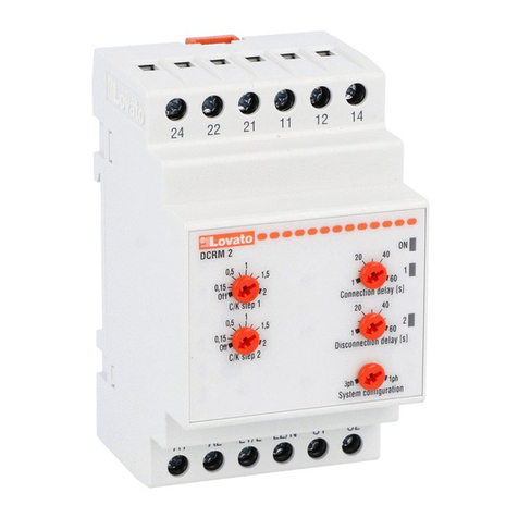
LOVATO ELECTRIC DCRM 2 User manual

LOVATO ELECTRIC

LOVATO ELECTRIC DCRM 2 User manual

LOVATO ELECTRIC RGK RR User manual

LOVATO ELECTRIC

LOVATO ELECTRIC RGK RR User manual

LOVATO ELECTRIC PMA20 User manual

LOVATO ELECTRIC

LOVATO ELECTRIC PMA20 User manual

LOVATO ELECTRIC PMA40 User manual

LOVATO ELECTRIC

LOVATO ELECTRIC PMA40 User manual

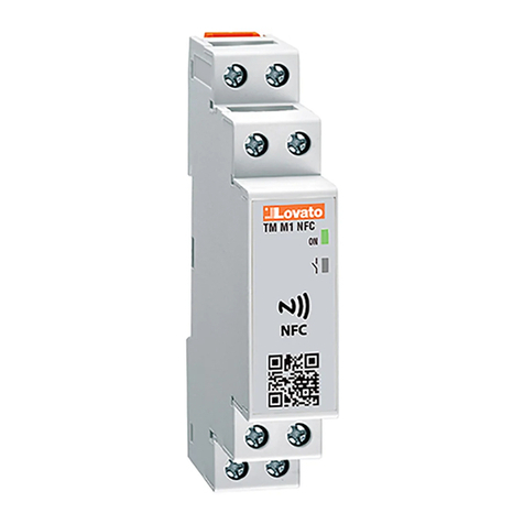
LOVATO ELECTRIC TMM1 NFC User manual

LOVATO ELECTRIC

LOVATO ELECTRIC TMM1 NFC User manual

LOVATO ELECTRIC PMA50 User manual

LOVATO ELECTRIC

LOVATO ELECTRIC PMA50 User manual

LOVATO ELECTRIC R1D User manual

LOVATO ELECTRIC

LOVATO ELECTRIC R1D User manual

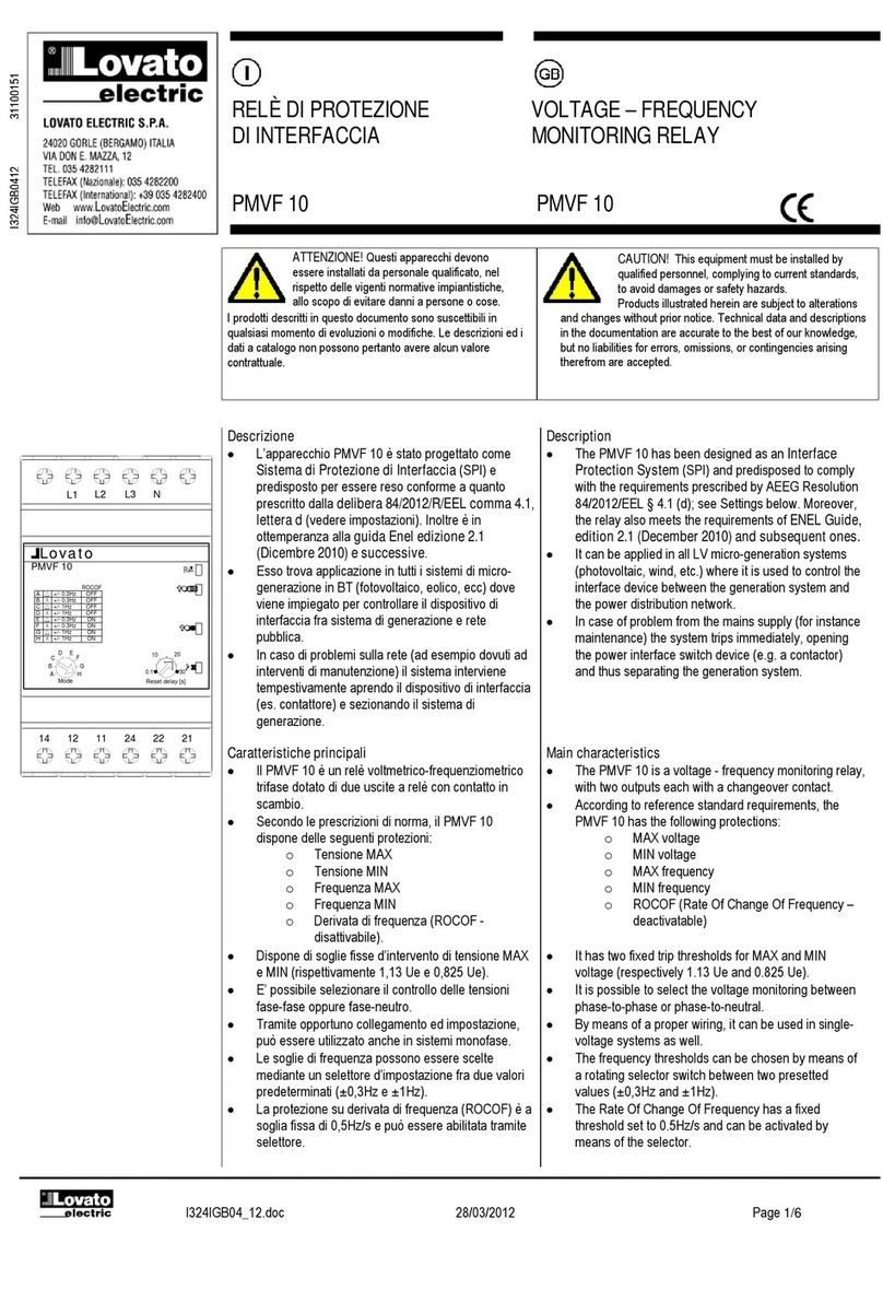
LOVATO ELECTRIC PMVF 10 User manual

LOVATO ELECTRIC

LOVATO ELECTRIC PMVF 10 User manual

LOVATO ELECTRIC EXP10 03 User manual

LOVATO ELECTRIC

LOVATO ELECTRIC EXP10 03 User manual

LOVATO ELECTRIC EXP1007 User manual

LOVATO ELECTRIC

LOVATO ELECTRIC EXP1007 User manual

LOVATO ELECTRIC SRB Series Instruction Manual

LOVATO ELECTRIC

LOVATO ELECTRIC SRB Series Instruction Manual

LOVATO ELECTRIC RGK RR User manual

LOVATO ELECTRIC

LOVATO ELECTRIC RGK RR User manual

LOVATO ELECTRIC TMM1 NFC User manual

LOVATO ELECTRIC

LOVATO ELECTRIC TMM1 NFC User manual

LOVATO ELECTRIC PMA60 User manual

LOVATO ELECTRIC

LOVATO ELECTRIC PMA60 User manual

LOVATO ELECTRIC LVM40 User manual

LOVATO ELECTRIC

LOVATO ELECTRIC LVM40 User manual

LOVATO ELECTRIC DRPT User manual

LOVATO ELECTRIC

LOVATO ELECTRIC DRPT User manual

LOVATO ELECTRIC PMV55 User manual

LOVATO ELECTRIC

LOVATO ELECTRIC PMV55 User manual

LOVATO ELECTRIC PMF20 User manual

LOVATO ELECTRIC

LOVATO ELECTRIC PMF20 User manual

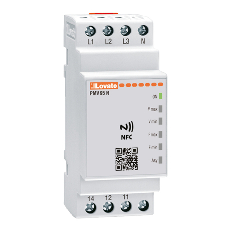
LOVATO ELECTRIC PMV95N***NFC Series User manual

LOVATO ELECTRIC

LOVATO ELECTRIC PMV95N***NFC Series User manual

LOVATO ELECTRIC PMV 50-N User manual

LOVATO ELECTRIC

LOVATO ELECTRIC PMV 50-N User manual

LOVATO ELECTRIC TM P A440 User manual

LOVATO ELECTRIC

LOVATO ELECTRIC TM P A440 User manual

Popular Relay manuals by other brands

Pilz 774065 manual

Pilz

Pilz 774065 manual

Schrack LSD3 Series operating instructions

Schrack

Schrack LSD3 Series operating instructions

IFM BasicController CR0431 Programming manual

IFM

IFM BasicController CR0431 Programming manual

FANOX PS 11-R quick start guide

FANOX

FANOX PS 11-R quick start guide

MULTISPAN VPR-22 Installation guidelines

MULTISPAN

MULTISPAN VPR-22 Installation guidelines

Ponovo PW460 Hardware instruction manual

Ponovo

Ponovo PW460 Hardware instruction manual

Bamo ES2001 instruction manual

Bamo

Bamo ES2001 instruction manual

Simons Voss Technologies SmartRelay SREL Series manual

Simons Voss Technologies

Simons Voss Technologies SmartRelay SREL Series manual

Omega Engineering DPA1004 user guide

Omega Engineering

Omega Engineering DPA1004 user guide

ABB Relion 615 series manual

ABB

ABB Relion 615 series manual

GRUP ARGE ZMN32 user manual

GRUP ARGE

GRUP ARGE ZMN32 user manual

Siemens 7SR210 Argus Application guide

Siemens

Siemens 7SR210 Argus Application guide

ZIEHL TR1200IP operating manual

ZIEHL

ZIEHL TR1200IP operating manual

Siemens 3RB22 Commissioning instructions

Siemens

Siemens 3RB22 Commissioning instructions

F&F PZ-829 RC quick start guide

F&F

F&F PZ-829 RC quick start guide

Reznor APD manual

Reznor

Reznor APD manual

Sven OVP-11F user manual

Sven

Sven OVP-11F user manual

Ei Electronics Ei128R instruction manual

Ei Electronics

Ei Electronics Ei128R instruction manual

manuals.online logo
manuals.online logoBrands
  • About & Mission
  • Contact us
  • Privacy Policy
  • Terms and Conditions

Copyright 2025 Manuals.Online. All Rights Reserved.