Lowenstein Medical VENTIremote alarm User manual

VENTIremote alarm
Remote alarm case
EN Instructions for Use

2 | EN
LMT 66735a 04/2021
Contents
Contents
1 Introduction 4
1.1 Intended use ................................................................................................................ 4
1.2 Description of function ................................................................................................. 4
1.3 Compatibility ............................................................................................................... 4
2 Safety 5
2.1 Safety information ........................................................................................................ 5
2.2 General information ..................................................................................................... 5
2.3 Safety information in these instructions ........................................................................ 6
3 Overview 7
3.1 Overview of remote alarm case .................................................................................... 7
3.2 Display film .................................................................................................................. 9
4 Preparation and operation 10
4.1 Before operating for the first time ............................................................................... 10
4.2 Setting up and connecting the device ......................................................................... 12
4.3 Operation with the therapy device .............................................................................. 14
4.4 Changing the battery ................................................................................................. 15
5 Hygiene treatment 17
5.1 Cleaning .................................................................................................................... 17
5.2 Disinfection ................................................................................................................ 17
5.3 Sterilization ................................................................................................................ 17
5.4 Change of patient ...................................................................................................... 17
6 Function check 18
6.1 Intervals ..................................................................................................................... 18
6.2 Performing the function check .................................................................................... 18
7 Troubleshooting 20
8 Servicing 20
9 Transport and storage 20
9.1 Disposal ..................................................................................................................... 20

LMT 66735a 04/2021
EN | 3
Contents
10 Annex 21
10.1 Technical specifications ............................................................................................. 21
10.2 Safety distances ........................................................................................................ 22
10.3 Markings and symbols ............................................................................................... 22
10.4 Standard scope of delivery ......................................................................................... 23
10.5 Accessories and spare parts ....................................................................................... 24
10.6 Warranty ................................................................................................................... 24
10.7 Declaration of Conformity .......................................................................................... 25

4 | EN
LMT 66735a 04/2021
Introduction
English
1 Introduction
1.1 Intended use
The VENTIremote alarm is for the remote transmission and display of acoustic and
visual alarm signals issued by the approved devices. Respiratory physiology alarms and
device faults can be monitored remotely using the VENTIremote alarm.
VENTIremote alarm is of particular assistance to nursing staff and relatives when
looking after a ventilated patient in a domestic environment.
1.2 Description of function
VENTIremote alarm is connected to the device via a cable (10 m and 30 m long). If the
device issues alarms, VENTIremote alarm converts these into visual and acoustic signals
and outputs them. The device is powered by a 9 V battery pack (lithium).
1.3 Compatibility
The VENTIremote alarm can be used with the following devices:
• LUISA (LM150TD)
• prisma VENT series (WM110TD/WM120TD)
(In combination with the prisma CHECK module)
• VENTIlogic LS/VENTIlogic plus series

LMT 66735a 04/2021
EN | 5
Safety
2 Safety
Please read these instructions for use carefully. They are a constituent part of the
device and must be available at all times. Only use the device for the intended purpose
described (see "1.1 Intended use", page 4).
For your own safety and the safety of your patients, and in accordance with the
requirements of (EU) Regulation 2017/745, observe the following instructions:
2.1 Safety information
Operating the device
Individuals may be injured if the product is damaged or its function is impaired.
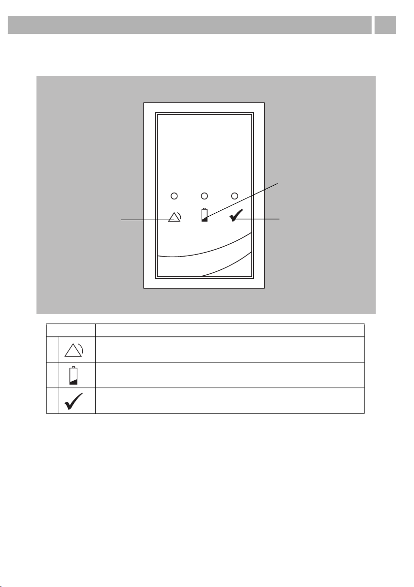
Ensure that the VENTIremote alarm is free-standing and not covered up, otherwise
alarm volume is reduced. This can lead to a risk to the patient and to damage to the
device.
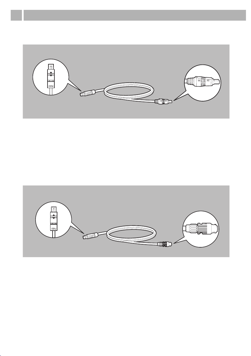
Ensure that the cable is connected correctly to prevent the connector being pulled out
inadvertently and to ensure that the VENTIremote alarm works correctly.
If the VENTIremote alarm has been stored or transported outside the operating
temperatures quoted in the instructions for use, the VENTIremote alarm should be
started up only once the temperature of the device is within the permitted range for
operation.
Electromagnetic compatibility
The product is subject to special precautions with regard to EMC (electromagnetic
compatibility). If these precautions are not followed, the product may malfunction and
individuals may be injured.
Maintain a safety distance between the VENTIremote alarm and equipment that emits
HF radiation (e.g. cell phones), otherwise there may be malfunctions.
2.2 General information
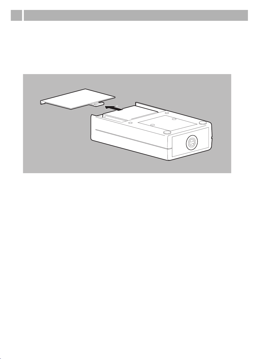
• Always keep a fully-charged U9VL-BP-type battery to hand. Remove the battery if the
VENTIremote alarm is being stored or not used for an extended period.
• To avoid infection or bacterial contamination, follow Section "5 Hygiene treatment",
page 17.
• Have measures such as repairs, servicing, and maintenance work, as well as
modifications to the product, carried out exclusively by the manufacturer or by
specialists expressly so authorized by the manufacturer.
• The use of third-party articles may lead to incompatibility with the device. In such
cases, please be aware that any claim under warranty and liability will be void if original
spare parts are not used.

6 | EN
LMT 66735a 04/2021
Safety
• In the EU: As a user and/or patient, you must report any serious incidents occurring in
conjunction with the product to the manufacturer and to the responsible authority.
2.3 Safety information in these instructions
Indicates an unusually significant hazardous situation. If you
ignore this instruction, severe irreversible or fatal injuries may
result.
Indicates a hazardous situation. If you ignore this instruction,
mild or moderate injuries may result.
Indicates a harmful situation. If you ignore this instruction,
material damage may result.
Indicates useful information within procedures.

LMT 66735a 04/2021
EN | 7
Overview
Deutsch
3 Overview
3.1 Overview of remote alarm case
1 ODU socket
This is where the ODU connector (two white arrows) of the cable is connected to the
VENTIremote alarm.
2 Stand-by indicator
This green LED indicates that the VENTIremote alarm is working correctly.
3 Battery indicator
If this yellow LED flashes, the battery needs changing.
4 Alarm indicator
In combination with the buzzer, this red LED indicates a therapy device alarm or
a malfunction of the VENTIremote alarm.
5 Device ID plate (Rear)
Provides information about the device, such as serial number and year of manufacture.
4
5
1
23

8 | EN
LMT 66735a 04/2021
Overview
3.1.1
Cable for LMT150TD
1 ODU connector
This connects the cable to the VENTIremote alarm.
2 Cable
This cable passes device alarms on to the VENTIremote alarm.
3 HRS connector
This connects the cable to the device.
3.1.2
Cable for VENTIlogic LS/VENTIlogic plus series, prisma CHECK
1 ODU connector
This connects the cable to the VENTIremote alarm.
2 Cable
This cable passes device alarms on to the VENTIremote alarm.
3 Bayonet connector
This connects the cable to the device.
1
2
3
1
2
3

LMT 66735a 04/2021
EN | 9
Overview
3.2 Display film
SYMBOL MEANING
1 Red LED on: Alarm
2 Yellow LED flashing every six seconds: Battery almost dead
3 Stand-by indicator: The green LED must light briefly every six seconds during
operation.
1
2
3

10 | EN
LMT 66735a 04/2021
Preparation and operation
4 Preparation and operation
4.1 Before operating for the first time
Before you can operate the VENTIremote alarm, you must insert the U9VL-BP-type
battery included in the scope of delivery.
1. Open the battery compartment.
2. Connect the battery to the connecting cables.

LMT 66735a 04/2021
EN | 11
Preparation and operation
3. Put the battery and the connecting cables in the battery compartment.
4. Push the battery compartment cover closed until it engages with an audible click.
The VENTIremote alarm is now ready for operation.
Notice!
Ensure that the connecting cables are underneath the battery in the battery
compartment, so that the connecting cables are not trapped when the battery
compartment is closed.

12 | EN
LMT 66735a 04/2021
Preparation and operation
4.2 Setting up and connecting the device
1. Place the VENTIremote alarm on a level surface.
2. Connecting to LMT150TD: Connect the ODU connector to the remote alarm
connection of the device.
Warning!
Ensure that the VENTIremote alarm is free-standing and not covered, otherwise
alarm volume will be reduced. This can lead to a risk to the patient and to
damage to the device.

LMT 66735a 04/2021
EN | 13
Preparation and operation
3. Connecting to prisma CHECK: Connect the bayonet connector to the remote
alarm connection of the device.
4. Connecting to VENTIlogic LS/VENTIlogic plus series: Connect the bayonet
connector to the remote alarm connection of the device.

14 | EN
LMT 66735a 04/2021
Preparation and operation
5. Connect the ODU connector (two white arrows) of the cable to the ODU socket of
the VENTIremote alarm. To do so, turn the ODU connector so that the arrows on
it and the arrow on the ODU socket are pointing at one another.
As soon as the ODU connector is connected to the VENTIremote alarm, the
VENTIremote alarm automatically performs a function check.
4.3 Operation with the therapy device
4.3.1
Switching on the VENTIremote alarm
The VENTIremote alarm is switched on as soon as it is connected to the device by the
cable. The stand-by indicator (green LED) on the VENTIremote alarm comes on briefly
every six seconds during operation to indicate operational readiness.
4.3.2
Output of alarms
If an alarm is issued on the therapy device, the alarm indicator (red LED) of the
VENTIremote alarm comes on permanently and a continuous acoustic signal sounds.
All alarms of medium and high priority, together with the power failure alarm (low
priority if the internal battery of the therapy device is charged), are passed on to the
VENTIremote alarm. In combination with prisma CHECK, all alarms of all priorities are
passed on. Look at the display of the therapy device to establish which alarm is
involved. A precise description of the alarm can be found in the instructions for use for
the therapy device. The alarm can be canceled by switching off/acknowledging the
alarm on the therapy device.
Notice!
Ensure that the connector engages correctly in the socket.

LMT 66735a 04/2021
EN | 15
Preparation and operation
4.3.3
Switching off the VENTIremote alarm
Switch off the VENTIremote alarm at the end of therapy by pulling out the ODU
connector of the cable of the VENTIremote alarm.
4.4 Changing the battery
The VENTIremote alarm is operated with a battery of the U9VL-BP type. As soon as the
battery indicator (yellow LED) comes on every six seconds and an acoustic alarm is
issued every six seconds, the battery of the VENTIremote alarm must be replaced.
To do so, proceed as follows:
1. Open the battery compartment.
2. Disconnect the battery from the connecting cables.
3. Connect the new battery to the connecting cables.

16 | EN
LMT 66735a 04/2021
Preparation and operation
4. Put the battery and the connecting cables in the battery compartment.
5. Push the battery compartment cover closed until it engages with an audible click.
Notice!
Ensure that the connecting cables are underneath the battery in the battery
compartment, so that the connecting cables are not trapped when the battery
compartment is closed.

LMT 66735a 04/2021
EN | 17
Hygiene treatment
5 Hygiene treatment
5.1 Cleaning
Wipe the VENTIremote alarm and the cable with a soft, damp cloth.
5.2 Disinfection
If required, e.g. following infectious diseases or unusual contamination, you can also
disinfect the housing of the VENTIremote alarm and the cable. We recommend
TERRALIN® for this purpose. See also the instructions for use for the disinfectant used.
We recommend using suitable gloves (e.g. household or disposable gloves) when
disinfecting.
5.3 Sterilization
Sterilization is not permitted.
5.4 Change of patient
On change of patient, disinfect the VENTIremote alarm (see "5 Hygiene treatment",
page 17).
Caution!
The VENTIremote alarm must be completely dry before being started up.

18 | EN
LMT 66735a 04/2021
Function check
6 Function check
As soon as the ODU connector is connected to the VENTIremote alarm,
the VENTIremote alarm automatically performs a function check.
If you find faults during the function check, you may not use the VENTIremote alarm.
Try to eliminate the fault (see "7 Troubleshooting", page 20). If this should prove
impossible, have the VENTIremote alarm repaired by the manufacturer or by specialists
expressly
authorized by the manufacturer.
A complete function check includes the following:
• Function check of the VENTIremote alarm (see "6.2.1 Function check of the
VENTIremote alarm", page 18)
• Function check of the battery (see "6.2.2 Function check of the battery", page 19)
• Function check of the entire system (see "6.2.3 Function check of the entire system",
page 19)
6.1 Intervals
Perform a function check daily and before the device is used each time.
6.2 Performing the function check
6.2.1
Function check of the VENTIremote alarm
To perform a function check, connect the cable to the VENTIremote alarm (see "4.2
Setting up and connecting the device", page 12).
VENTIremote alarm is working correctly if all three LEDs come on briefly at the same
time and a short acoustic signal sounds.
Notice!
VENTIremote alarm starts the function check even if the connector is not yet fully
engaged.
Ensure that the connector engages correctly in the socket.
Notice!
If the cable is already connected to the VENTIremote alarm, briefly pull out the ODU
connector and then reconnect it to the ODU socket.

LMT 66735a 04/2021
EN | 19
Function check
6.2.2
Function check of the battery
To establish the charging state of the battery, proceed as follows:
1. Check the battery indicator:
• The charging state of the battery is OK if the battery indicator does not come on.
• If the battery indicator comes on every 6 seconds, the battery needs replacing.
2. Check the stand-by indicator:
• The charging state of the battery is OK if the stand-by indicator comes on every
6 seconds.
• If the stand-by indicator and the battery indicator do not come on every 6 seconds,
the battery needs replacing.
6.2.3
Function check of the entire system
To check the connection between the VENTIremote alarm and the device, proceed as
follows:
1. Connect the VENTIremote alarm to the device (see "4.2 Setting up and connecting
the device", page 12).
2. Switch on the therapy device and then unplug it from the power supply.
The therapy device and thus also the VENTIremote alarm are working correctly if both
now issue an alarm:
• VENTIremote alarm is working correctly if the alarm indicator (red LED) comes
on continuously and a continuous acoustic signal sounds.
• The therapy device is working correctly if the yellow LED comes on and an acoustic
signal sounds. The alarm window "No power supply voltage" appears in the
display.

20 | EN
LMT 66735a 04/2021
Troubleshooting
7 Troubleshooting
8 Servicing
The VENTIremote alarm requires no servicing.
The device is designed for a service life of 6 years.
9 Transport and storage
Always transport and store the VENTIremote alarm dry. Remove the battery if the
VENTIremote alarm is in storage or not being used for an extended period.
9.1 Disposal
Do not dispose of the device, nor of any batteries/battery packs, in domestic
waste. To dispose of the device properly, contact a licensed, certified electronic
waste disposal merchant. This address is available from your Environment
Officer or from your local authority. The device packaging (cardboard and
inserts) can be disposed of in paper recycling facilities.
FAULT CAUSE OF FAULT REMEDY
VENTIremote alarm does
not switch on
Battery discharged Insert new batteryBuzzer and/or LEDs not working
Battery indicator (yellow LED) flashes
and buzzer sounds every 6 seconds
Alarm indicator (red LED) on +
acoustic alarm
Cable is damaged Check cable for damage and
replace if necessary
HRS connector/bayonet connector
not connected to the device
Check fit of HRS connector/
bayonet connector in device
Alarm on therapy device Check alarm on therapy device
Stand-by indicator (green LED)
does not come on after 6 seconds
Battery discharged Insert new battery
ODU connector not correctly
connected to VENTIremote alarm
Make sure ODU connector is
engaged in ODU socket
Other manuals for VENTIremote alarm
1
Table of contents
Other Lowenstein Medical Security System manuals