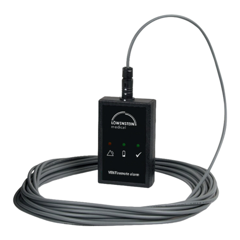
Lowenstein Medical VENTIremote alarm User manual

VENTIremote alarm
Remote alarm case
EN Instructions for Use

2Overview
EN
Overview
Key
1 Battery indicator
If this yellow LED flashes, the battery needs
changing.
2 Alarm indicator
In combination with the buzzer, this red LED indi-
cates an alarm of the therapy device or a malfunc-
tion of the VENTIremote alarm.
3Nameplate
Provides information about the device, such as
serial number and year of manufacture, for
example.
4ODUsocket
This is where the ODU connector (two white
arrows) for the connecting cable to the
VENTIremote alarm is connected.
5 Stand-by indicator
This green LED indicates that the VENTIremote
alarm is working correctly.
6 Connecting cable
This connecting cable passes alarms from the
device to the VENTIremote alarm.
VENTIremote alarm
4ODU socket
5Stand-by indicator 1Battery indicator 2Alarm indicator
3Nameplate
6Connecting cable
7Bayonet
connector
8ODU connector

Special markings on the device 3
EN
7 Bayonet connector
This connects the connecting cable to the device.
8 ODU connector
This connects the connecting cable to the
VENTIremote alarm.
Special markings on the device
Symbols Significance
Name plate
Serial number
Manufacturer
Follow information in the instructions for use
Do not dispose of device in domestic waste
Display fascia
1Red LED illuminated: alarm
2Yellow LED flashing every six seconds: battery almost dead
3Stand-by indicator: the green LED must light briefly every six seconds
during operation
VENTIremote alarm
VENTI
remote alarm
123Name plate
SN

4Safety information in these instructions
EN
Safety information in these
instructions
Safety information in these instructions for use is marked as follows:
Warning!
Warns of risk of injury and potential material damage.
Caution!
Warns of material damage and potentially false therapy results.
Note:
Contains useful tips.

Contents 5
EN
Contents
1. Description of device . . . . . . . . . . 6
1.1 Intended use. . . . . . . . . . . . . . . . . 6
1.2 Description of function . . . . . . . . 6
2. Safety instructions . . . . . . . . . . . . 7
3. Set up and operate the
device . . . . . . . . . . . . . . . . . . . . . . . 9
3.1 Initial commissioning . . . . . . . . . . 9
3.2 Set up and connect the device . . 10
3.3 Operation with the therapy
device . . . . . . . . . . . . . . . . . . . . . 11
3.4 Change battery. . . . . . . . . . . . . . 11
4. Hygienic preparation . . . . . . . . . 13
4.1 Cleaning. . . . . . . . . . . . . . . . . . . 13
4.2 Disinfecting . . . . . . . . . . . . . . . . 13
4.3 Sterilizing . . . . . . . . . . . . . . . . . . 13
4.4 Change of patient . . . . . . . . . . . 13
5. Function check . . . . . . . . . . . . . . . 14
5.1 Intervals . . . . . . . . . . . . . . . . . . . 14
5.2 Performing the function check . . 15
6. Troubleshooting . . . . . . . . . . . . . 17
7. Servicing . . . . . . . . . . . . . . . . . . . . 17
7.1 Storage. . . . . . . . . . . . . . . . . . . . 17
7.2 Disposal . . . . . . . . . . . . . . . . . . . 17
8. Scope of supply . . . . . . . . . . . . . . 18
8.1 Standard scope of supply . . . . . . 18
8.2 Accessories and spare parts . . . . 18
9. Technical data . . . . . . . . . . . . . . . 19
9.1 Specifications . . . . . . . . . . . . . . . 19
9.2 Safety distances . . . . . . . . . . . . . 20
10. Warranty . . . . . . . . . . . . . . . . . . . . 21
11. Declaration of conformity . . . . . 22

6Description of device
EN
1. Description of device
1.1 Intended use
VENTIremote alarm is for the remote transmission and display of acoustic and visual alarm
signals issued by the VENTIlogic LS, VENTIlogic plus and prisma CHECK (WM 100 MS) de-
vices. With VENTIremote alarm, alarms relating to respiratory physiology and device faults
can be remotely monitored independent of any nurse-call system which may be installed.
VENTIremote alarm helps in particular nursing staff and family members when caring for a
ventilated patient in the home environment.
1.2 Description of function
VENTIremote alarm has a connecting cable (10 m and 30 m long) to connect it to the de-
vice. If the device issues alarms, the VENTIremote alarm converts these into visual and
acoustic signals and outputs them. The device is powered by a 9 V battery pack (lithium).

Safety instructions 7
EN
2. Safety instructions
Read these instructions for use carefully. They are an integral part of the device and must
be available at all times. Only use the device for the intended purpose described (see “1.1
Intended use” on page 6).
For your own safety and the safety of your patients and in accordance with the
requirements of Directive 93/42/EEC, please note the following:
Operating the device
Warning!
• Ensure that the VENTIremote alarm is free-standing and not covered up,
otherwise alarm volume is reduced. This can lead to a risk to the patient and to
damage to the device.
• Maintain a safe distance between the VENTIremote alarm and equipment that
emits HF radiation (e.g. cell phones), otherwise there may be malfunctions.
Caution!
• To prevent infection or bacterial contamination, observe section “4. Hygienic
preparation” on page 13.
• Ensure that the connecting cable is correctly connected to prevent the connector
being pulled out inadvertently and to ensure that the VENTIremote alarm works
correctly.
Note:
Always keep a full U9VL-BP-type battery to hand.
Transport/Replacement parts/Maintenance/Storage
Caution!
• If the VENTIremote alarm has been stored or transported outside the operating
temperatures quoted in the instructions for use, the VENTIremote alarm should
be commissioned only once the temperature of the device is within the
permitted range for operation.

8Safety instructions
EN
• If third-party items are used, functional failures may occur and fitness for use
may be restricted. Biocompatibility requirements may also not be met. Please
note that in such cases, any claim under warranty and liability will be voided if
neither the accessories nor genuine replacement parts recommended in the
instructions for use are used.
• Have servicing and maintenance work carried out only by the manufacturer or
by specialists expressly authorized to do so by the manufacturer.
• Have modifications to the device carried out only by the manufacturer or by
specialists expressly authorized to do so by the manufacturer.
Note:
• Remove the battery if the VENTIremote alarm is in storage or not being used for
an extended period.
• In the event of questions about faults, see the section entitled “6.
Troubleshooting” on page 17.

Set up and operate the device 9
EN
3. Set up and operate the device
3.1 Initial commissioning
Before you can operate the VENTIremote alarm as described below, you have to insert the
U9VL-BP-type battery included in the scope of supply. To do so, proceed as follows.
1. Open the battery compartment as shown in the
adjacent drawing.
2. Connect the battery to the connecting cables.
3. Put the battery and the connecting cables in the
battery compartment.
Note:
Ensure that the connecting cables are underneath
the battery in the battery compartment, so that
the connecting cables are not trapped when the
battery compartment is closed.
4. Push the battery compartment cover closed until it
engages with an audible click.
VENTIremote alarm is now ready for operation.

10 Set up and operate the device
EN
3.2 Set up and connect the device
1. Place the VENTIremote alarm on a level surface.
Warning!
Ensure that the VENTIremote alarm is free-standing and not covered, otherwise
alarm volume will be reduced. This can lead to a risk to the patient and to damage
to the device.
2. Connect the bayonet connector of the connecting
cable to the remote alarm connection of the device.
3. Connect the ODU connector (two white arrows) of
the connecting cable to the ODU socket of the
VENTIremote alarm. To do so, turn the ODU connec-
tor so that the arrows on it and the arrow on the
ODU socket are pointing at one another.
As soon as the ODU connector is connected to the
VENTIremote alarm, the VENTIremote alarm
automatically performs a function check.
Note:
Ensure that the connector engages correctly in
the socket.

Set up and operate the device 11
EN
3.3 Operation with the therapy device
Switch on VENTIremote alarm
VENTIremote alarm is switched on as soon as it is connected to the device by the connect-
ing cable. The stand-by indicator (green LED) on the VENTIremote alarm comes on briefly
every six seconds during operation to indicate operational readiness.
Output of alarms
If an alarm is issued on the therapy device, the alarm indicator (red LED) of the VENTIremote
alarm comes on permanently and a continuous acoustic signal sounds. All alarms of medi-
um and high priority, together with the power failure alarm (low priority if the internal bat-
tery of the therapy device is charged) are passed on to the VENTIremote alarm. In
combination with prisma CHECK, all alarms of all priorities are passed on. Look at the dis-
play of the therapy device to establish which alarm is involved. A precise description of the
alarm can be found in the Instructions for Use for the therapy device. The alarm can be
cancelled by switching off/acknowledging the alarm on the therapy device.
Switch off VENTIremote alarm
Switch off the VENTIremote alarm at the end of therapy by pulling out the ODU connector
of the connecting cable of the VENTIremote alarm.
3.4 Change battery
VENTIremote alarm is operated with a battery of the U9VL-BP type. As soon as the battery
indicator (yellow LED) comes on every six seconds and an acoustic alarm is issued every six
seconds, the battery of the VENTIremote alarm must be replaced. To do so, proceed as
follows:
1. Open the battery compartment as shown in the
adjacent drawing.
2. Take the battery off the connecting cables.
3. Connect the new battery to the connecting cables.

12 Set up and operate the device
EN
4. Put the battery and the connecting cables in the bat-
tery compartment.
Note:
Ensure that the connecting cables are underneath
the battery in the battery compartment, so that
the connecting cables are not trapped when the
battery compartment is closed.
5. Push the battery compartment cover closed until it engages with an audible click.
Note:
Always keep a full U9VL-BP-type battery to hand.

Hygienic preparation 13
EN
4. Hygienic preparation
4.1 Cleaning
Caution!
The VENTIremote alarm must be completely dry before starting up.
Wipe the VENTIremote alarm and the connecting cable with a soft, damp cloth.
4.2 Disinfecting
If required, e.g. following infectious diseases or unusual contamination, you can also dis-
infect the housing of the VENTIremote alarm and the connecting cable. We recommend
terralin®protect for this purpose. See the instructions for use for the disinfectant used. For
disinfecting, we recommend that suitable gloves (e.g. domestic gloves or disposable
gloves) are used.
4.3 Sterilizing
Sterilizing is not permitted.
4.4 Change of patient
Disinfect the VENTIremote alarm when changing patients as described in “4.2
Disinfecting” on page 13.

14 Function check
EN
5. Function check
As soon as the ODU connector is connected to the VENTIremote alarm, the VENTIremote
alarm automatically performs a function check.
Note:
VENTIremote alarm starts the function check even if the connector is not yet fully
engaged. Ensure that the connector engages correctly in the socket.
If you find faults during the function check, you may not use the VENTIremote alarm.
Try to eliminate the fault with the aid of the information in the section entitled “6.
Troubleshooting” on page 17. If this should prove impossible, have the VENTIremote alarm
repaired by the manufacturer or by specialists expressly authorized by the manufacturer.
A complete function check includes the following.
• “ VENTIremote alarm function check” on page 15
• “ Battery function check” on page 15
• “ Function check of the entire system” on page 16
5.1 Intervals
Perform a function check daily and each time before the device is used.

Function check 15
EN
5.2 Performing the function check
VENTIremote alarm function check
In order to perform a function check, connect the connecting cable to the VENTIremote
alarm as described in the section entitled “3.2 Set up and connect the device” on page 10.
Note:
If the connecting cable is already connected to the VENTIremote alarm, briefly pull
out the ODU connector and then reconnect it to the ODU socket.
VENTIremote alarm is working correctly if all three LEDs come on briefly at the same time
and a short acoustic signal sounds.
Battery function check
To establish the charging state of the battery, proceed as follows.
1. Check the battery indicator
• The charging state of the battery is OK if the battery indicator does not come on.
• If the battery indicator comes on every 6 seconds, the battery needs changing.
2. Check the stand-by indicator
• The charging state of the battery is OK if the stand-by indicator comes on every
6 seconds.
• If the stand-by indicator and the battery indicator do not come on every
6 seconds, the battery needs changing.

16 Function check
EN
Function check of the entire system
To check the connection between the VENTIremote alarm and the device, proceed as
follows.
1. Connect the VENTIremote alarm to the device (see “3.2 Set up and connect the device”
on page 10).
2. Switch on the therapy device and then pull out its power plug.
The therapy device and thus the VENTIremote alarm are working correctly if both now issue
an alarm:
• VENTIremote alarm is working correctly if the alarm indicator (red LED) comes
on continuously and a continuous acoustic signal sounds.
• The therapy device is working correctly if the yellow LED comes on and an
acoustic signal sounds. The alarm window “No power supply” appears in the
display.

Troubleshooting 17
EN
6. Troubleshooting
7. Servicing
VENTIremote alarm requires no servicing.
7.1 Storage
Always store the VENTIremote alarm dry. Remove the battery if the VENTIremote alarm is
in storage or not being used for an extended period.
7.2 Disposal
Do not dispose of the device, nor of any batteries/battery packs, as domestic waste.
To dispose of the device properly, contact a licensed, certified electronic scrap dis-
posal merchant. You can find out their address from your environment officer or
from your municipal authorities. The device packaging (cardboard and inserts) can
be disposed of in paper recycling facilities.
Fault Cause of fault Remedy
VENTIremote alarm does not
switch on
Battery discharged Insert new batteryBuzzer and/or LEDs not working
Battery display (yellow LED) flashes
and buzzer sounds every 6 s
Alarm indicator (red LED) on +
alarm sound
Connecting cable damaged
Check connecting cable for
damage and replace if
necessary
Bayonet connector not
connected to the device
Check if bayonet connector is
properly connected to the
device
Alarm on the therapy device Check alarm on the therapy
device
Stand-by indicator (green LED)
does not come on after 6 s
Battery discharged Insert new battery
ODU connector not correctly
connected to VENTIremote alarm
Make sure ODU connector is
engaged in ODU socket

18 Scope of supply
EN
8. Scope of supply
8.1 Standard scope of supply
VENTIremote alarm, 10 m, packed WM 27745
VENTIremote alarm, 30 m, packed WM 27755
8.2 Accessories and spare parts
A current list of accessories and replacement parts can be ordered on the internet site of
the manufacturer or through your authorized specialist dealer.
Description Order no.
VENTIremote alarm WM 27764
Connecting cable, 10 m, VENTIremote alarm WM 27789
Battery, 9 V, lithium WM 12166
Instructions for use for VENTIremote alarm EN WM 66731
Description Order no.
VENTIremote alarm WM 27764
Connecting cable, 30 m, VENTIremote alarm WM 27758
Battery, 9 V, lithium WM 12166
Instructions for use for VENTIremote alarm EN WM 66731

Technical data 19
EN
9. Technical data
9.1 Specifications
We reserve the right to make changes to the design.
VENTIremote alarm
Battery type 9 V lithium, U9VL-BP
Dimensions (WxHxD)
in cm 60 x 25 x 96
Weight 250 g
Temperature range
Operation
Storage
+5 °C to +40 °C
–40 °C to +70 °C
Signal volume 80 dB ±4 dB with a full battery at 1 m distance
Battery life approx. 100 days at 1 min alarm a day
Classification to
EN 60601-1:2006 Internal power supply 9 V
Standards applied EN 60601-1-8:2007
There may be a delay of up to 2 seconds in passing on the call.

20 Technical data
EN
9.2 Safety distances
Recommended safety distances between portable HF telecommunications devices
(e.g. cell phones) and the VENTIremote alarm
Nominal output of
HF equipment
in W
Safety distance depending on transmission frequency
in m
150 kHz - 80 MHz 80 MHz – 800 MHz 800 MHz – 2.5 GHz
0.01 0.04 0.04 0.08
0.1 0.11 0.11 0.22
1 0.35 0.35 0.70
10 1.10 1.10 2.20
100 3.50 3.50 7.00
Other manuals for VENTIremote alarm
1
Table of contents
Other Lowenstein Medical Security System manuals