Page 2
Quick Hardware Setup Guide
and inspect it for damage. If the card appears damaged, contact
LSI Logic or your MegaRAID OEM support representative.
Step 2: Power Down
Turn off the computer and remove the cover. Make sure the
computer is disconnected from any networks before installing the
controller card.
Step 3: Configure Motherboard
Make sure the motherboard is configured correctly for MegaRAID
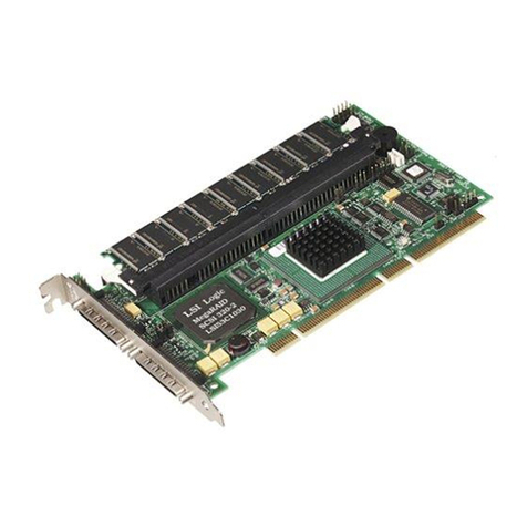
Express 300. MegaRAID Express 300 is essentially a SCSI
controller. Each MegaRAID Express 300 card you install will require
an available PCI IRQ; make sure an IRQ is available for each
controller you install.
Step 4: Install Cache Memory
Use 72-bit 3.3 V unbuffered SDRAM only. The maximum memory
bandwidthis 528 MB/sec.
For more information on SDRAM specifications, refer to the
MegaRAID Express 300 Hardware Guide.
Important:
A minimum of 16 MB of cache memory is required. The
cache memory must be installed before MegaRAID
Express 300 is operational.
Install cache memory on the MegaRAID Express 300 card in the
DIMM socket. This socket accepts a 168-pin DIMM.
Lay the controller card component-side up on a clean static-free
surface to install the DIMM. The memory socket is mounted flush
with the MegaRAID Express 300 card, so the DIMM will stand at a
right angle to the MegaRAID card when properly installed. The
DIMM clicks into place, indicating proper seating in the socket.
Step 5: Set Jumpers
Make sure the jumper settings on the MegaRAID Express 300 card
are correct. Jumper setting details can be found in the Hardware
Installation Manual. The jumpers and connectors are:
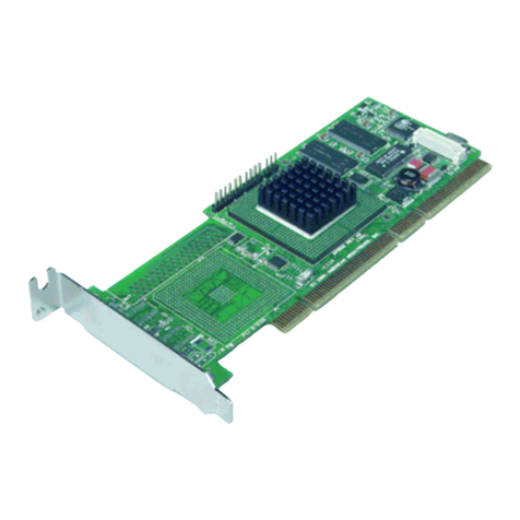
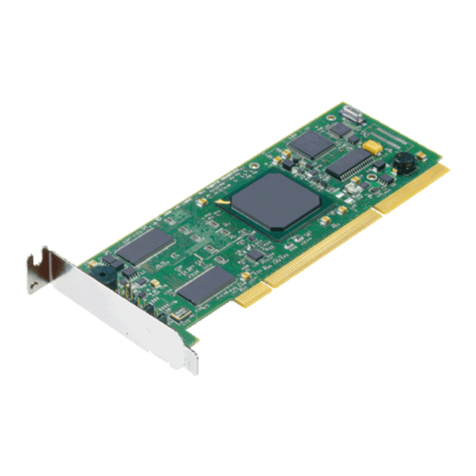
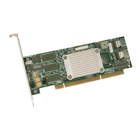
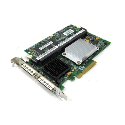
MegaRAID Express 300 Card Layout
Step 6: Set Termination
You must terminate the SCSI bus properly. Set termination at both
ends of the SCSI cable. The SCSI bus is an electrical transmission
line and must be terminated properly to minimize reflections and
losses. Termination is always enabled, regardless of the
configuration. However, you can override this setting by setting
another state.
J10 Termination Enable: J10 is a three-pin header that specifies
hardware or software control of SCSI termination.
Step 7: Set Terminator Power (TermPWR)
Important:
Both MegaRAID Express 300 SCSI channels need
TermPWRto operate. If a channel is not being used and
no auxiliary power source is connected, change the
jumper setting for that channel to supply TermPWR from
the PCI bus.
J14 Term Power: J14 is a 2-pin jumper. The factory setting is Pins
1-2 shorted. Pins 1-2 should always be shorted for J14 to enable
onboard term power.
Step 8: Installing the MegaRAID Express 300
Choose a 3.3 V PCI slot and align the MegaRAID Express 300
controller card bus connector to the slot. Press down gently but
firmly to make sure the card is properly seated in the slot. The
bottom edge of the controller card should be flush with the slot.
Step 9: Connect the SCSI cables to the SCSI devices
Connect the SCSI cables to the SCSI devices. The MegaRAID
Express 300 controller provides two types of connectors: one
internal high-density 68-pin SCSI connectors and one external ultra
high-density 68-pin SCSI connectors.
Connector Description Type
J16 I2C connector 4-pin header
J17 BIOS enable 2-pin header
J18 Serial EPROM 2-pin header
J19 JTAG 4-pin header
J3 Serial port 10-pin header
J5 Internal straddle-mount connector 68-pin connector
J4 External SCSI connector 68-pin connector
J7 User activity LED 4-pin connector
J10 SCSI bus termination enable\dis-
able control 3-pin header
J14 SCSI bus termination power 2-pin header
J12 Rub1 slot interrupt steering 3-pin header
J13 Rub1 slot interrupt steering 3-pin header
J15 Rub1 slot interrupt steering 3-pin header
Type of SCSI Termination J1 Setting
Software control of SCSI termination via drive
detection. Short Pins 1-2
Permanently disable all onboard SCSI
termination. Short Pins 2-3
Permanently enable all onboard SCSI
termination. OPEN
