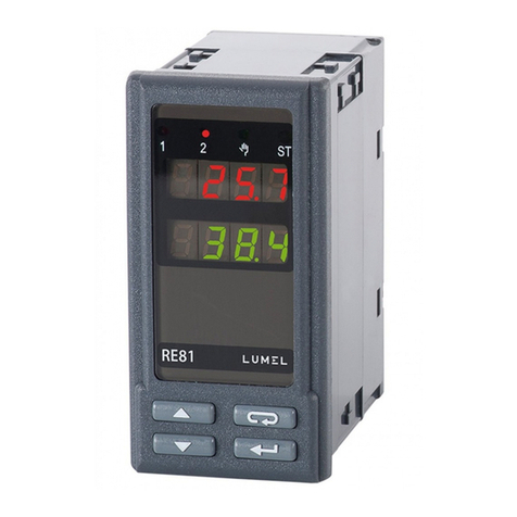
Lumel RE22 User manual

REGULATOR ZUNIWERSALNYM WEJŚCIEM
i1 WYJŚCIEM
CONTROLLER WITH UNIVERSAL INPUT
AND 1 OUTPUT
RE22
INSTRUKCJA OBSŁUGI - SZYBKI START
Pełna wersja instrukcji dostępna na
Full version of user’s manual available at
www.lumel.com.pl
USER’S MANUAL - QUICK START PL
EN
Zeskanuj mnie
Zeskanuj kod Scan the code

2
pl
1. WYMAGANIA PODSTAWOWE,
Regulator RE22 spe³nia wymagania dotycz¹ce bezpieczeñstwa
elektrycznych przyrz¹dów pomiarowych automatyki wg normy
PN-EN 61010-1, wymagania dotycz¹ce odpornoœci na zak³ócenia
elektromagnetyczne wg normy PN-EN 61000-6-2 oraz emisji zak³óceñ
elektromagnetycznych wystêpuj¹cych w œrodowisku przemys³owym wg
normy PN-EN 61000-6-4.
2.1. Instalowanie regulatora
Przymocowaæ regulator do tablicy dwoma uchwytami œrubowymi
wg rys.1. Otwór w tablicy powinien mieæ wymiary 45+0,6 x 45+0,6 mm.
Gruboœæ materia³u, z którego wykonano tablicê, nie mo¿e przekraczaæ 15 mm.
Rys. 1. Mocowanie regulatora
Wymiary regulatora przedstawiono na rys. 2.
Rys.2 Wymiary regulatora.

3
pl
Rys.6. Wygl¹d p³yty czo³owej regulatora.
Opis regulatora
Za³¹czenie zasilania
Po za³¹czeniu zasilania regulator wykonuje test, wyœwietla napis re22,
wersjê programu, a nastêpnie wyœwietla wartoœæ mierzon¹.
Na wyœwietlaczu mo¿e byæ komunikat znakowy informuj¹cy
o nieprawid³owoœciach (tab. 4 - patrz pełna wersja instrukcji obsługi
dostępna na www.lumel.com.pl).
Fabrycznie ustawiony jest algorytm regulacji za³¹cz-wy³¹cz z histerez¹ 2oC.
Zmiana wartoœci zadanej
Sposób zmiany wartoœci zadanej podczas normalnej pracy jest
pokazany na rysunku 7. Ograniczenie zmiany jest ustawiane parametrami
SPL i SPH.
Rys.7. Zmiana wartoœci zadanej podczas normalnej pracy.

4
pl
4.
4.1. Schemat menu regulatora
Schemat menu regulatora przedstawiono na rys.8 (str.5). Po naciœniêciu
i przytrzymaniu przez co najmniej 2 sekundy przycisku , mo¿liwe jest
programowanie parametrów. Przechodzenie pomiêdzy parametrami od-
bywa siê za pomoc¹ przycisków i . Opis parametrów zawiera
tab. 1. Powrót do normalnego trybu pracy nastêpuje po jednoczesnym
naciœniêciu przycisków i lub automatycznie po up³ywie 30
sekund od ostatniego naciœniêcia przycisku. Niektóre parametry mog¹
byæ niewidoczne - uzale¿nione jest to od aktualnej konfiguracji regulatora.
Dostêp do parametrów mo¿na zabezpieczyæ kodem. Je¿eli jest usta-
wiony kod bezpieczeñstwa (parametr seCU jest wiêkszy od zera),
nale¿y go podaæ. Je¿eli wartoœæ nie zostanie podana lub bêdzie
ona b³êdna na wyœwietlaczach pojawi siê napis err, a u¿ytkownik
bêdzie móg³ jedynie przegl¹daæ wartoœci parametrów.
4.2. Zmiana nastawy
Zmianê nastawy parametru rozpoczyna siê po naciœniêciu przyci-
sku . Przyciskami i dokonuje siê wyboru nastawy,
a przyciskiem akceptuje. Anulowanie zmiany nastêpuje po jed-
noczesnym naciœniêcie przycisków i lub automatycznie po
up³ywie 30 sekund od ostatniego naciœniêcia przycisku. Sposób zmiany
nastawy pokazano na rys.9.
Rys.9. Zmiana nastawy parametrów liczbowych i tekstowych.

5
pl
Rys.8. Menu obs³ugi
regulatora

6
pl
Typ czujnika Norma Oznaczenie Zakres Symbol
na
wyœwietlaczu
Pt100 PN-EN 60751+A2 Pt100 -199...850°C pt1
Pt1000 PN-EN 60751+A2 Pt1000 -199...850°C pt10
Fe-CuNi PN-EN 60584-1 J -100...1200°C t-,
Cu-CuNi PN-EN 60584-1 T -100...400°C t-t
NiCr-NiAl PN-EN 60584-1 K -100...1372°C t-k
PtRh10-Pt PN-EN 60584-1 S 0...1767°C t-s
PtRh13-Pt PN-EN 60584-1 R 0...1767°C t-r
PtRh30-PtRh6 PN-EN 60584-1 B 0...1820°C t-b
NiCr-CuNi PN-EN 60584-1 E -100...999°C t-e
NiCrSi-NiSi PN-EN 60584-1 N -100...1300°C t-n
chromel-kopel GOST R 8.585 L -100...800°C t-l
Sygna³y wejœciowe oraz zakresy pomiarowe dla wejœæ czujników
Tablica 1
Typ czujnika Oznaczenie Zakres Symbol
na wyœwietlaczu
Liniowe pr¹dowe I 0...20 mA 0-20
Liniowe pr¹dowe I 4...20 mA 4-20
Liniowe napiêciowe U 0...5 V 0-5
Liniowe napiêciowe U 0...10 V 0-10
Sygna³y wejœciowe oraz zakresy pomiarowe dla wejœæ liniowych
Tablica 2
Sygna³y wejœciowe: - dla wejœæ czujników wg tablicy 1
- dla wejϾ liniowych wg tablicy 2
B³¹d podstawowy pomiaru wartoœci rzeczywistej:
0,2%, dla wejϾ termorezystancyjnych,
0,3%, dla wejœæ dla czujników termoelektrycznych (0,5% - dla B, R, S);
0,2% ± 1 cyfra, dla wejœæ liniowych
Czas pomiaru: dla wejœæ czujników 0,33 s; dla wejœæ liniowych 0,16 s
Rezystancja wejœciowa: dla wejœcia napiêciowego 150 k;
dla wejœcia pr¹dowego 4

7
pl
Wykrywanie b³êdu w obwodzie pomiarowym:
- termopara, Pt100, PT1000 przekroczenie zakresu pomiarowego
- 0...10 V powy¿ej 11 V
- 0...5 V powy¿ej 5,25 V
- 0...20 mA powy¿ej 22 mA
- 4...20 mA poni¿ej 1mA i powy¿ej 22 mA
Algorytm regulacji: P, PD, PI, PID, dwustawna z histerez¹
Zakres nastaw parametrów regulatora patrz tablica 1 (patrz pełna
wersja instrukcji obsługi)
Rodzaje wyjœæ: przekaŸnikowe: styk prze³¹czny,
obci¹¿alnoœæ maksymalna: napiêciowa: 250 V a.c., 150 V d.c. pr¹dowa:
5 A 250 V a.c., 5 A 30 V d.c.
obciążenie rezystancyjne 1250 VA,150 W
binarne napiêciowe (bez izolacji od strony czujnika) napiêcie 5 V
rezystancja ograniczajaca pr¹d 66 ;
Sposób dzia³ania wyjœæ: rewersyjne dla grzania, wprost dla ch³odzenia
Sygnalizacja: za³¹czenia wyjœcia g³ównego; wyœwietlania wartoœci
zadanej; trybu regulacji rêcznej; trybu autoadaptacji
Znamionowe warunki u¿ytkowania
- napiêcie zasilania: 230 V a.c. ± 10 %; 110 V a.c. ± 10 %; 24 V a.c. ± 10 %
- czêstotliwoœæ napiêcia zasilania: 50/60 Hz
- temperatura otoczenia: 0...23...50 °C
- temperatura przechowywania: -20...+70 °C
- wilgotnoœæ wzglêdna powietrza < 85 % (bez kondensacji pary wodnej)
- zewnêtrzne pole magnetyczne < 400 A/m
- czas wstêpnego nagrzewania: 30 min
- po³o¿enie pracy: dowolne
- rezystancja przewodów ³¹cz¹cych rezystor termometryczny z regula-
torem < 20
Pobór mocy < 3 VA Masa < 0,25 kg
Stopieñ ochrony zapewniany przez obudowê wg PN-EN 60529
od strony p³yty czo³owej IP40, od strony zacisków IP20
B³êdy dodatkowe w znamionowych warunkach u¿ytkowania spo-
wodowane:
- kompensacj¹ zmian temperatury spoin odniesienia termoelementu 2oC,
- zmian¹ temperatury otoczenia 100% wartoœci b³êdu podstawowego /10 K.
8
pl
Wymagania bezpieczeñstwa wg PN-EN 61010-1
- kategoria instalacji III
- stopieñ zanieczyszczenia 2
- maksymalne napiêcie pracy wzglêdem ziemi:
- dla obwodu zasilania, wyjœcia 300 V
- dla obwodów wejœciowych 50 V
KompatybilnoϾ elektromagnetyczna
- odpornoœæ na zak³ócenia elektromagnetyczne wg normy PN-EN
61000-6-2
- emisja zak³óceñ elektromagnetycznych wg normyPN-EN 61000-6-4
RE22 X X X XX X
Wejście:
uniwersalne dla czujników termoelektrycznych i termorezy-
stancyjnych 1
uniwersalne liniowe: prądowe: 0/4..20 mA, napięciowe: 0..5/10V 2
na zamówienie X
Wyjście:
przekaźnikowe 1
binarne 0/5 V do sterowania SSR 2
na zamówienie* X
Zasilanie:
230 V 50/60 Hz 1
110 V 50/60 Hz 2
24 V 50/60 Hz 3
na zamówienie X
Rodzaj wykonania:
standardowe 00
specjalne* XX
Wymagania dodatkowe:
bez dodatkowych wymagań 0
z atestem Kontroli Jakości 1
wg uzgodnień z odbiorcą X
* tylko po uzgodnieniu z producentem

9
EN
SAFETY
The RE22 controller fulfils requirements concerning the safety of
automation measuring instruments acc. to the EN 61010-1 standard,
requirements concerning the fastness against electromagnetic inter-
ference acc. to EN 61000-6-2 standard and emission of electromag-
netic interference occurring in the industrial environment, acc. to the
EN 61000-6-4 standard.
2.1. Controller Installation
Fix the controller in the panel by means of two screw holders acc.
to the fig.1. The hole in the panel should have 45+0.6 x 45+0.6 mm dimensions.
The material thickness what the panel is made of cannot exceed 15 mm.
Fig.1. Controller fixing.
Controller overall dimensions are presented on the fig. 2.
Fig.2. View of controller connection strips.

10
EN
Controller description
After connecting to the power, the controller carries out the display
test and displays the re22 inscription, the program version,
and next, displays the measured value.
A character message can appear on the display, informing about abnor-
malities (table 4 - see full version of user’s manual).
The algorithm of ON-OFF control with a 2oC hysteresis is set by
the manufacturer.
Fig.6. View of the controller frontal plate.
Change of the set point
The way to change the set point during the normal work is shown on the
fig. 7. The change limitation is set by SPL and SPH parameters.
Fig.7. Change of the set point during the normal work.

11
EN
4.
4.1. Scheme of the controller menu
After pressing and holding the push-button during at least
2 sec., it is possible to program parameters. The transition between
parameters is carried out by means of and push-buttons.
The return to the normal working mode follows after the simultaneous
pressure of and push-buttons, or automatically, after
30 sec from the last push-button pressure.
Some parameters can be invisible - it depends on the current controller
configuration.
The access to parameters can be protected by a code. If the safety code
is set (parameter seCU is higher than zero), one must give it. If the
value will not be given or will be erroneous, the inscription err appears
on displays, and the user will be only able to monitor parameter values.
4.2. Setting change
The change of parameter setting begins after pressing the
push-button. By means of and push-buttons we make
the choice of the setting, and by the push-button we accept it.
The cancellation of the change follows after the simultaneous
pressure of and lpush-buttons or automatically after
30 sec. from the last push-button pressure. The way of setting
change is presented on the fig.8.
Fig.8. Setting
change of numerical
and textual
parameters.

12
EN
Fig.9.
Menu of controller
servicing

13
EN
Sensor type Standard Notation Range Symbol
on the
display
Pt100 EN 60751+A2 Pt100 -199...850°C pt1
Pt1000 EN 60751+A2 Pt1000 -199...850°C pt10
Fe-CuNi EN 60584-1 J -100...1200°C t-,
Cu-CuNi EN 60584-1 T -100...400°C t-t
NiCr-NiAl EN 60584-1 K -100...1372°C t-k
PtRh10-Pt EN 60584-1 S 0...1767°C t-s
PtRh13-Pt EN 60584-1 R 0...1767°C t-r
PtRh30-PtRh6 EN 60584-1 B 0...1820°C t-b
NiCr-CuNi EN 60584-1 E -100...999°C t-e
NiCrSi-NiSi EN 60584-1 N -100...1300°C t-n
chromel-kopel GOST R 8.585 L -100...800°C t-l
Input signals and measuring ranges for sensor inputs.
Sensor type Notation Range Symbol on
the display
Linear current input I 0...20 mA 0-20
Linear current input I 4...20 mA 4-20
Linear voltage input U 0...5 V 0-5
Linear voltage input U 0...10 V 0-10
Input signals and measuring ranges for linear
inputs
Input signals: for sensor inputs acc. to table 1, for linear inputs acc. to table 2
Basic error of true value measurement: 0.2%, for RTD inputs,
0.3%, for TC inputs (0.5% - for B, R, S), 0.2% ± 1 digit, for linear inputs
Table 1
Table 2
Measurement time: for sensor inputs 0.33, for linear inputs 0.16 s
Input resistance: for voltage input 150 k, for current input 4
Detection of error in the measuring circuit:
- thermocouple, Pt100, PT1000 overrunning of the measuring range
- 0...10 V over 11 V
- 0...5 V over 5.25 V

14
EN
- 0...20 mA over 22 mA
- 4...20 mA under 1 mA and over 22 mA
Control algorithm: P, PD, PI, PID, too-state with hysteresis
Range of controller parameter settings: see table 1 (see full version
of user’s manual)
Kind of outputs: relay: switch over contact, maximal load-carrying
capacity: voltage: 250 V a.c., 150 V d.c., current: 5 A 250 V a.c., 5 A30 V d.c.
resistance load: 1250 VA, 150 W
binary voltage (without isolation from the sensor side): voltage 5 V
resistance limiting the current 66 ;
Way of output action: reverse for heating, direct for cooling
Signalling: output switching on, display of set point, manual control
mode, auto-tuning mode
Rated service conditions:
- supply voltage: 230 V a.c. ± 10 %, 110 V a.c. ± 10 %, 24 V a.c. ± 10 %
- supply voltage frequency: 50/60 Hz
- ambient temperature: 0...23...50 °C
- storage temperature: -20...+70 °C
- relative air humidity < 85 % (without condensation)
- external magnetic field < 400 A/m
- preheating time: 30 min
- work position: any
- resistance of wires connecting the resistance thermometer
with the controller< 20
Power consumption < 3 VA Weight < 0.25 kg
IP protection ensured through the housing: acc. to EN 60529:
from the frontal side IP40, from terminal side IP20
Additional errors in rated working conditions caused by:
- compensation of the thermocouple cold junction 2oC,
- ambient temperature change 100% of the basic error value/10 K.
Safety requirements acc. to EN 61010-1: - installation category III
- level of pollution: 2
- maximal working voltage in relation to ground:
- for supply circuit, outputs 300 V
- for input circuits 50 V
Electromagnetic compatibility:
- immunity acc. to EN 61000-6-2
- emission acc. to EN 61000-6-4

15
EN
X X X XX X
Input:
1
2
as per order X
Output:
1
2
as per order X
Supply:
1
2
as per order X
Version:
standard
XX
Additional quality requirements:
8
7
X

pl EN
Wykonaæ pod³¹czenia elektryczne do listew zaciskowych a nastêpnie
listwy wcisn¹æ do gniazd regulatora.
Rys.3 Widok listew pod³¹czeniowych regulatora.
Carry out electrical connections to terminal strips and next, insert strips
into controller sockets.
Fig.3. View of controller connection strips.
sygnały wejściowe/
input signals wyjście/ output
zasilanie/
supply
termorezystor Pt100
w uk³adzie
2-przewodowym
termorezystor Pt100
w uk³adzie
3-przewodowym
termorezystor
Pt1000
Pt100 resistance
thermometer
in 2-wire system
Pt100 resistance
thermometer
in 3-wire system
Pt1000 resistance
thermometer

PL EN
17
termoelement wejœcie pr¹dowe
0/4..20 mA wejœcie napiêciowe
0..5/10 V
Rys.4. Pod³¹czenie sygna³ów wejœciowych.
Thermocouple Current input
0/4..20mA Voltage input
0..5/10V
Fig.4. Connection of input signals.
When connecting the supply, one must remember that an automatic cut-
-off should be installed near the device, easily accessible for the operator
and suitably marked.
zasilanie / Supply
Output - relay
Output - binary voltage to control SSR
Fig.5. Connection of the supply and load circuit.
wyjœcie - przekaŸnik
wyjœcie - binarne napiêciowe do sterowania SSR
zasilanie / supply
zasilanie / supply
Rys.5. Pod³¹czenie zasilania i obwodu obci¹¿enia
Przy pod³¹czaniu zasilania nale¿y pamiêtaæ, ¿e w instalacji budynku
powinien byæ wy³¹cznik lub wy³¹cznik automatyczny, umieszczony
w pobli¿u urz¹dzenia, ³atwo dostêpny dla operatora i odpowiednio
oznakowany.

pl EN
18
Zalecenia instalacyjne
Regulator RE22 spe³nia wymagania dotycz¹ce odpornoœci na zak³ócenia
elektromagnetyczne wystêpuj¹ce w œrodowisku przemys³owym wg
obowi¹zuj¹cych norm.
W celu uzyskania pe³nej odpornoœci regulatora na zak³ócenia elektro-
magnetyczne w œrodowisku o nieznanym poziomie zak³óceñ zaleca
siê przestrzeganie nastêpuj¹cych zasad:
- nie zasilaæ regulatora z sieci w pobli¿u urz¹dzeñ wytwarzaj¹cych
du¿e zak³ócenia impulsowe,
- stosowaæ filtry sieciowe,
- do prowadzenia przewodów zasilaj¹cych stosowaæ ekrany metalowe
w postaci rurek lub oplotów,
- przewody doprowadzaj¹ce sygna³y pomiarowe powinny byæ skrêcone
parami, a dla czujników oporowych w po³¹czeniu trójprzewodowym
skrêcane z przewodów o tej samej d³ugoœci, przekroju i rezystancji,
oraz prowadzone w ekranie jw.,
- wszystkie ekrany powinny byæ uziemione jednostronnie jak najbli¿ej
regulatora,
- stosowaæ ogóln¹ zasadê, ¿e przewody wiod¹ce ró¿ne sygna³y powin-
ny byæ prowadzone w jak najwiêkszej odleg³oœci od siebie (nie mniej
ni¿ 30 cm), a skrzy¿owanie tych wi¹zek wykonywane pod k¹tem 90o.

PL EN
19
Installation recommendations
The RE22 controller fulfils requirements concerning the fastness
against electromagnetic interference occurring in the industrial
environment acc. to obligatory standards.
In order to obtain a full immunity of the controller against electro-
magnetic interference in an unknown environment interference level
it is recommended to observe following principles:
- do not supply the controller from the network near devices generating
high impulse interference and do not use common earthing circuits
with them,
- apply network filters,
- apply metallic shields in the shape of tubes or braided screens to
conduct supplying wires,
- wires supplying the measuring signal should be twisted in pairs,
and for resistance thermometers in a 3-wire connection, twisted from
wires with the same length, cross-section and resistance, and led
in a shield as above,
- all screens should be one side earthed, and led the nearest possible
to the controller,
- apply the general principle that wires leading different signals should
be led the farthest possible between them (not less than 30 cm),
and their crossing executed at a right angle.

RE22-07,09
Informacja techniczna:
tel.: (68) 45 75 306, 45 75 180, 45 75 260
e-mail: [email protected]
Realizacja zamówień:
tel.: (68) 45 75 207, 45 75 209, 45 75 218, 45 75 341
fax.: (68) 32 55 650
LUMEL S.A.
ul. Sulechowska 1, 65-022 Zielona Góra, Poland
tel.: +48 68 45 75 100, fax +48 68 45 75 508
www.lumel.com.pl
Pracownia systemów automatyki:
tel.: (68) 45 75 228, 45 75 117
Wzorcowanie:
tel.: (68) 45 75 161
e-mail: [email protected]
Export department:
tel.: (+48 68) 45 75 139, 45 75 233, 45 75 321,
45 75 386, 45 75 353
fax.: (+48 68) 32 54 091
e-mail: expor[email protected]
Calibration & Attestation:
tel.: (68) 45 75 161
e-mail: [email protected]
Table of contents
Languages:
Other Lumel Controllers manuals