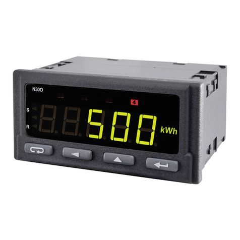
Lumel N30O User manual

1
DIGITAL
PANEL METER
N30O TYPE
USER’S MANUAL

2

3
Contents
1. APPLICATION AND METER DESIGN ........................................5
2. METER SET..................................................................................6
3. BASIC REQUIREMENTS, OPERATIONAL SAFETY .................7
4. INSTALLATION............................................................................8
5. SERVICE ....................................................................................12
6. RS-485 INTERFACE ..................................................................36
7. SOFTWARE UPDATING............................................................50
8. ERROR CODES .........................................................................52
9. TECHNICAL DATA ....................................................................53
10. PROGRAMMING EXAMPLES ...................................................56
11. ORDER CODES .........................................................................58
12. MAINTENANCE AND GUARANTEE.........................................60

4

5
1. APPLICATION AND METER DESIGN
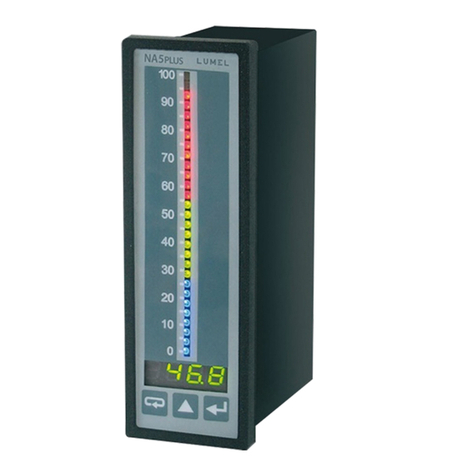
The programmable digital panel meter N30O is destined for measu-
rements: number of pulses, frequency, period, worktime, encoder
position. Additionally, the meter enables the indication of the current
time. The readout field is a LED display, which allows the exposition
in colours: red, green and orange. The measured input signal can be
arbitrary converted by means of mathematic functions and/or a 21-point
individual characteristic.
Features of the N30O Meter:
ldisplay colour individually programmed in three ranges,
lprogrammable thresholds of displayed overflows,
l2 NOC relay alarms operating in 6 modes,
l2 switched relay alarms with a switching contact operating
in 6 modes (option),
lsignaling of measuring range overflow,
lautomatic setting of the decimal point,
lprogramming of alarms and analog outputs with the reaction
on the selected input quantity (main or auxiliary input),
ladditional counter input,
lcontrol inputs of the main input work, additional or both simultaneously,
lsignaling of additional input state,
lpossible control of counter operation by means of the meter keyboard,
lautomatic reset of counters at the set point value
lreal-time clock with the function of the clock supply support in case
of the meter supply decay,
lprogrammed averaging time – function of walking window with the
averaging time up to 1 hour,
lmonitoring of set parameter values,
llocking of introduced parameters by means of a password,
lmathematic functions for measured value calculation,
lrecount of the measured quantity on the base of the 21-point
individual characteristic,

6
2. METER SET
The set is composed of:
- N30O meter......................................... 1 pc
- user’s manual...................................... 1 pc
- guarantee card ................................... 1 pc
- set of clamps to fix in the panel .......... 4 pcs
- seal...................................................... 1 pc
When unpacking the meter, please check whether the type and option
code on the data plate correspond to the order.
linterface with MODBUS protocol in the RTU mode (option),
lfirmware updating by RS485 interface (option)
lconversion of the measured value into a standard – programmable
current or voltage signal (option),
lhighlight of any measuring unit acc. to the order.
lsignaling of alarm operation – switching the alarm on causes the
highlight of the output number,
lgalvanic separation of pulse inputs between them,
lgalvanic separation between terminals: alarm, supply, input,
analog output, auxiliary supply, RS-485 interface.
Protection grade from frontal side: IP65
Meter overall dimensions: 96 x 48 x 93 mm (with terminals).
The meter casing is made of plastic.
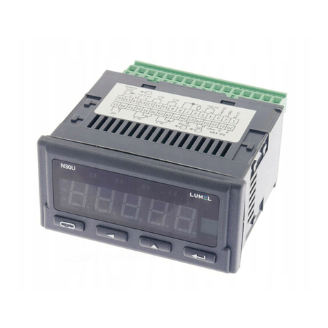
Fig. 1 View of the N30O Digital Meter

7
3. BASIC REQUIREMENTS, OPERATIONAL
SAFETY
In the safety service scope, the N30O meter meets the requirements of
the EN 61010-1 standard.
Mentioned below applied symbols mean:
- especially important, one must acquaint with this information
before connecting the meter. The non-observance of notices
marked by this symbol can occasion injures of the personnel
and a damage of the instrument.
- one must take note of this when the instrument is working
inconsistently to the expectations. Possible consequences
if disregarded.
Observations concerning the operational safety
· All operations concerning transport, installation, and commissioning
as well as maintenance, must be carried out by qualified, skilled
personnel, and national regulations for the prevention of accidents
must be observed.
· Before switching the meter on, one must check the correctness
of connections.
· The meter is designed to be installed and exploited in
electromagnetic industrial environment conditions.
· When connecting the supply, one must remember that a switch or a
circuit-breaker should be installed in the building. This switch should
be located near the device, easy accessible by the operator, and
suitably marked as an element switching the meter off.
· Non-authorized removal of the housing, inappropriate use, incorrect
installation or operation, creates the risk of injury to personnel or
meter damage.
For more detailed information, please study the User’s Manual.

8
Fig. 3. Overall Dimensions
Fig. 2. Meter Fixing
4. INSTALLATION
The meter has separable strips with screw terminals, what enables the
connection of external wires of 1.5 mm2cross-section for input signals
and 2.5 mm2for other signals.
One must prepare a hole of 92+0,6 ´45+0,6 mm in the panel, which the
thickness should not exceed 6 mm.
The meter must be introduced from the panel front with disconnected
supply voltage. Before the insertion into the panel, one must check the
correct placement of the seal. After the insertion into the hole, fix the
meter by means of clamps (fig. 2).

9
Fig. 4. Description of Signals on Connection Strips
4.1. Lead-out of Signals
Signals led out on the meter connectors are presented on the fig. 4.
All input signals are separated between them and separated from
other circuits. Circuits of successive groups of signals are separated
between them.
Clamps Description Clamps Description
1-2
3-4
5-6
7-8
9-10
W3- Main input. Counting of pulses
downwards.
W2 - Additional input. Auxiliary
counter.
W1- Main input. Counting of pulses
upwards/ work time.
RST- Reset input (reset) of the main
counter or/and auxiliary counter.
The function is available after swit-
ching in the meter menu on.
S/S – start/stop of counting. The
function is available after switching
in the meter menu on.
11-12
13-14
15-16
17-18
20-21-22
23-24
25-26
27-28-29
30-31-32
34-35
alarm output 1, relay
alarm output 2, relay
24 V external transducer supply
output
supply
RS-485 output
analog output 1, voltage
analog output 1, current
alarm output 3, relay
alarm output 4, relay
OC – open collector output of
npn type– signaling of the range
overflow.

10
4.2. Examples of Connections
An example of a N30O meter and a inductive sensor connection with
an output of NPN and PNP type is presented on the fig. 5. The way to
connect a transducer with an output of contactron/relay type is pre-
sented on the fig. 6. In examples, the connection of the main input W1
is shown. Other inputs are connected in the same way but we must
remember, that all inputs are galvanically separated between them and
have a system limiting the input current. The range of voltages control-
ling the input should be in the 5..24 V d.c. range.
a)

11
Fig. 5. Connection of the sensor with the OC Output:
a) NPN Type b) PNP Type.
Fig. 6. Connection of the sensor with the Reed Relay/ Relay Output
Type
b)

12
5. SERVICE
5.1. Display Description
Fig. 7. Description of the Meter Frontal Plate
5.2. Messages after Switching the Supply on
After switching the supply on, the meter displays the meter name N30O
and next, the program version in the shape „ x.xx” – where x.xx is the
number of the current program version or the number of a custom-
made option. Next, the meter carries out measurements and displays
the value of the input signal. The meter sets up automatically the de-
cimal point position when displaying the value. The format (number of
places after the decimal point) can be limited by the user.
5.3. Functions of Buttons
- Acceptation button:
Þentry in programming mode (press and hold down ca 3 seconds),
has not gone by

13
Þmoving through the menu – choice of level,
Þentry in the mode changing the parameter value,
Þacceptation of the changed parameter value,
Þstop the measurement – when holding down the button, the result
on the display is not updated.
The measurement is still carried out.
- button increasing the value:
Þdisplay of maximal value, The pressure of the button causes the
display of the maximal value during ca 3 seconds,
Þentry in the level of the parameter group,
Þmoving through the selected level,
Þchange of the selected parameter value – increasing the value.
- button changing the digit:
Þdisplay of minimal value, The pressure of the button causes the
display of the minimal value during ca 3 seconds,
Þentry in the level of parameter group,
Þmoving through the selected level,
Þchange of selected parameter value – shift on the next digit,
- resignation button:
Þentry in the menu monitoring the meter parameters (by holding
down ca 3 seconds),
Þexit from the menu monitoring meter parameters,
Þresignation of the parameter change,
Þabsolute exit from the programming mode (holding down
ca 3 seconds).
The pressure of the button combination and holding
them down ca 3 seconds causes the erasing of alarm signaling. This
operation acts only when the support function is switched on.
The pressure of the button combination causes the era-

14
5.4. Programming
The pressure of the button and holding it down through ca 3
seconds causes the entry in the programming matrix. If the entry is pro-
tected by a password, then the safety code symbol SEC is displayed
alternately with the set up value 0. The write of the correct code causes
sing of the minimal value.
The pressure of the button combination causes the era-
sing of the maximal value.
The pressure of the button combination causes the display
of the second counter contents. A longer holding down (longer
than 3 seconds) causes the reset of the main counter (if the ser-
vice of counters from the keyboard is switched on). The auxiliary
counter is reset only from the Inp2 counter.
The pressure of the button combination longer than
3 seconds causes counting stop (for pulse counter and work time coun-
ter mode), in case when the button function is on.
The pressure of the button combination longer than
3 seconds causes count start (for pulse counter and work time counter
mode), in case when the button function is on.
The pressure and holding down the button during 3 seconds
causes the entry to the programming matrix. The programming matrix
can be proteced wit security code.
The pressure and holding down the button during 3 seconds
causes the entry to the menu monitoring meter parameters . One must
move through the monitoring menu by means of and
buttons. In this menu, all programmable meter parameters are only ava-
ilable for readout. In this mode, the menu Ser is not available. The exit
from the monitoring menu is carried out by means of the button.
In the monitoring menu, parameter symbols are displayed alternately
with their values.
The service algorithm of the meter is presented on the fig. 8.

15
Rys 8
Wejœcie w tryb
programowania
Wyœwietlenie
napisu
ErCod
kasowanie wartoœci
minimalnej
kasowanie wartoœci
maksymalnej
kasowanie
pamiêci
alarmów
niepoprawne
poprawne
POMIAR
Reset
liczników
ZawartoϾ licznika
dodatkowego
Wprowadzenie
has³a
Wyœwietlanie
wartoœci
minimalnej
3 sekundy3 sekundy
Sprawdzenie
has³a
Menu podgl¹du
parametrów
miernika
Stop licznika
Start licznika
Wyœwietlanie
wartoœci
maksymalnej
3 sekundy
3 sekundy
3 sekundy
3 sekundy
MEASUREMENT
Display of the
inscription
ErCod
Erasing of the
minimal value
Erasing of the
maximal value
Erasing
of the
alarm memory
Reset
of
counters
Contents of the
additional counter
Introduction
of the password
Display
of
minimal value
3 seconds
Checking the
password
Incorrect
Entry in the
programming
mode
Correct
Menu for
montoring meter
parameters
Counter stop
Counter start
3 seconds
3 seconds
3 seconds
3 seconds
Display
of
maximal value
Fig. 8. Service Algorithm of the N30O Meter

16
Item
1
Inp 1
Para-
meters
of main
input
tYP1
Type of
Measured
quantity
SCAL1
Choice of
method to
convert
Input
quantity
ConS1
Constant
to convert
the input
quantity
t_L1
Miinimal
Time of low
pulse level
duration
t_H1
Maximal
time of
upper
pulse level
duration
E_In1
Permit for
external
functions
Auto1
Automatic
reset of
counters
Cnt1
Measure-
ment time
FUnCt
Mathe-
matic
fun-
ctions
-----
2Inp 2
Para-
meters
of
auxiliary
input
Cntr2
Contents
of
auxiliary
input
SCAL2
Choice of
metod
to rescale
Input
quantities
ConS2
Constant
rescaling
Input
quantity
t_L2
Minimal
Time of low
pulse level
duration
t_H2
Maximal
time of
upper
pulse level
duration
E_In2
Permit for
external
function
Auto2
Automatic
reset of
counters
CLr2
Cancel
the
counter
-----
3Ind
Para-
meters of
individ.
Charact.
IndCp
Number
of points
of
Individ.
charact.
H1
First point
of the
Individ.
oharact.
Point x.
Y1
First point
of the
Individ.
Charact.
Point x.
... H21
Last point
of the
characte-
ristic
Y21
Last point
of the
charac-
teristic
-----
4dISP
Display
parame-
ters
d_P
Miinimal
decimal
point
coldo
Lower
colour
colbe
Middle
colour
colup
Upper
colour
colLo
Lower
threshold
of colour
change
colHi
Upper
threshold
of colour
change
ovrLo
Lower
overflow
ovrHi
Upper
overflow
-----
5ALr1
Alarm 1
P_A1
Tyoe of
Input
quantity
for
alarm 1
PrL1
Lower
threshold
PrH1
Upper
threshold
tYP1
Alarm
type
dLY1
Alarm
delay
LED1
Signaling
support
-----

17
Fig. 9. Programming Matrix.
6ALr2
Alarm 2
P_A2
Tyoe of
Input
quantity
for
alarm 2
PrL2
Lower
threshold
PrH2
Upper
threshold
tYP2
Alarm
type
dLY2
Alarm
delay
LED2
Signaling
support
-----
7ALr3
Alarm 3
P_A3
Tyoe of
input
quantity
for
alarm 3
PrL3
Lower
threshold
PrH3
Upper
threshold
tYP3
Alarm
type
dLY3
Alarm
delay
LED3
Signaling
support
-----
8 ALr4
Alarm 4
P_A4
Tyoe of
Input
quantity
for
alarm 4
PrL4
Lower
threshold
PrH4
Upper
threshold
tYP4
Alarm
type
dLY4
Alarm
delay
LED4
Signalling
support
-----
9Out
Outputs
P_An
Type of
quantity
for the
analog
output
Anl
Lower
threshold
for the
analog
output
AnH
Upper
threshold
for the
analog
output
typ_A
Kind of
output
(volt/
current)
bAud
Baud
rate
prot
Kind of
frame
addr
Device
address
-----
10 SEr
Service
Set
Write
standard
parame-
ters
SEC
Introduce
the
password
Hour
Setup of
the time
unIt
Highligth
the unit
tESt
Display
test
-----

18
5.4.1. Value Change Way of the Chosen Parameter
In order to increase the value of the selected parameter, one must
press the button. A single pressure of the button, causes the
increase of the value of 1. The increase of value when displaying the di-
git 9 causes the setting of 0 on this digit. The change of the digit follows
after pressing the button.
In order to accept the set up parameter, one must hold down the
button. Then, the write of the parameter and the display of its symbol
follows alternately with the new value. The pressure of the but-
ton during the change of the parameter value will cause the resignation
of the write.
5.4.2. Changing Floating-Point Values
The change is carried out in two stages (the transition to the next stage
follows after pressing the button):
1) setting the value from the range -19999...99999, similarly as for in-
tegral values;
the entry in the matrix, the write of an incorrect code causes the display
of the ErCod symbol. The matrix of transitions into the programming
mode is presented on the fig. 9. The selection of the level is made by
means of the button, however the entry and moving through
the parameters of the chosen level is carried out by means of
and buttons. Parameter symbols are displayed alternately with
their current values. In order to change the value of the selected pa-
rameter, one must use the button. To resign from the change,
one must use the button. In order to exit from the selected le-
vel, one must chose the ----- symbol and press the button. To
exit from the programming matrix, one must press the -button
during ca 1 second. Then, the inscription End appears for ca 3 se-
conds and the meter displays the measured value. In case of leaving
the meter in the parameter programming mode, the automatic aban-
don of the programming mode parameter (parameter, next the menu)
follows after 30 seconds and the meter displays the measured value.

19
2) setting of the decimal point position (00000., 0000.0, 000.00, 00.000,
0.0000); the button shifts the decimal point to the left, howe-
ver the button shifts the decimal point to the right;
The pressure of the button during the change of the parameter
value will cause the resignation of the write.
Table 1
InP 1
Para-
meter
symbol
Description Range of changes
tYP1 Selection of measured value
Cntr – number of pulses
FrEqL – frequency for
(f < 10 kHz)
FrEqH – frequency for
(f > 10 kHz)
tACH – rotational speed
PEr – period
PErH – long period > 10 s.
CntH – worktime counter.
Hour – current time
Enc – incremental encoder
SCAL1 Selection of input quantity rescaling. Mea-
sured value is multiplied or divided by the
set point value (parameter ConS).
And – multiplication by the
constant
diu – division by the constant
ConS1
Constant rescaling the input quantity.
The write of a negative value causes
the counting down (mode of pulse
counter and worktime counter).
-19999...99999
t_L1
Minimal duration time of the low level
pulse on the main input. The intro-
duction of a value lower than 0.25 or
5 causes the switching of the length
control function of the low signal level
off. The value is given in milliseconds.
0...60000

20
Table 1
t_H1
Minimal duration time of the high level
pulse on the main input. The introduc-
tion of a value lower than 0.25 or 5
causes the switching of the length con-
trol function of the high signal level off.
The value is given in milliseconds.
Parameters t_L1 and t_H1 define the
maximal frequency value.
(minimalsignalperiod =t_L1+t_H1 + 0,2s).
0...60000
E_In1
Permit for external functions: start/stop,
erasing. Taken into consideration only
in counter modes: pulse counter and
worktime counter. The meter counts
only by the passed high level signal
on the input W1 near external func-
tions switch on the worktime counter.
bUt – External functio switched
off. Access to functions only
from the level of meter buttons.
In – functions switched off.
External functions switched
on. Access by means of but-
tons is switched off.
bUtIn – External functions
switched on. Access by means
of buttons and additional
inputs. Higher priority have
external inputs. The option of
the counter erasing is available
from the keyboard level.
Auto1
In the counter working modes, the
counter value is automatically erased
after reaching this value. The write of
the value 0 switches the function off.
In the working mode of low frequency
measurement, speed, periods, it is the
time in seconds of the measurement
duration (waiting for the pulse).
-19999...99999
Cnt1
The measurement time is expressed
in seconds. The result on the display
presents the mean value counted in
the Cnt1 period. This parameter is not
taken into consideration during the
measurement in counter modes.
1...3600
Other manuals for N30O
2
Table of contents
Other Lumel Measuring Instrument manuals
Popular Measuring Instrument manuals by other brands

Elma Instruments
Elma Instruments Elma 9200BT manual

Hioki
Hioki CT9691 installation manual

Exotek Instruments
Exotek Instruments MC-60CPA user manual

PCE Americas
PCE Americas PCE-WM 1 manual

Dwyer Instruments
Dwyer Instruments RVM Specifications-installation and operating instructions

ELMETRON
ELMETRON CX-461 user manual

Airmar
Airmar WeatherStation 200WXRS Owner's guide & installation instructions

Qu-Bit Electronix
Qu-Bit Electronix EON manual

Velleman
Velleman DVM8080 user manual

KROHNE
KROHNE OPTIMASS 1000 Series Guidelines for use

Simpson
Simpson S664 Operation manual

Cleveland Controls
Cleveland Controls 6650 instruction manual