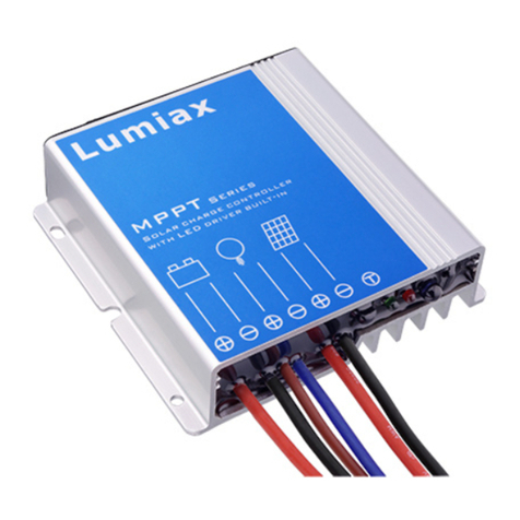
Lumiax MPPT Series User manual

MPPT SOLAR
CHARGE CONTROLLER
MPPT SERIES
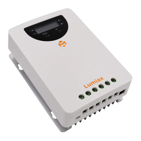
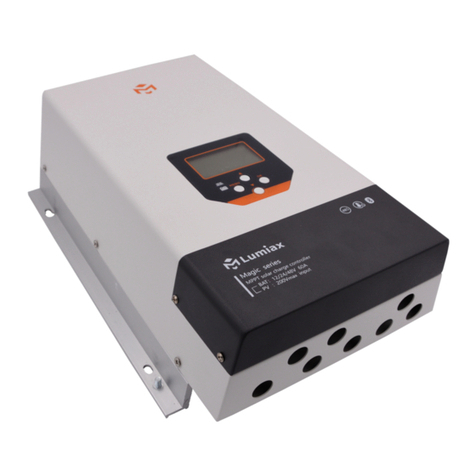
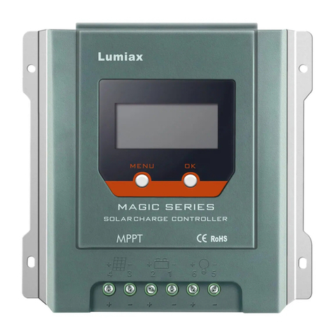
※ THE IMAGE SHOWN HERE IS INDICATIVE ONLY. PLEASE REFER TO THE ACTUAL PRODUCT

CONTENTS
1. Safety Instructions
2. Introduction and Functions
2.1. Introduction
2.2. Function and protection
3. Front-panel description
4. Mounting and Connection
4.1. Connecting to the battery
4.2. Connecting to the solar panel
4.3. Connecting to the load
4.4. Grounding the Solar System
4.5. Replacing the internal fuse
5. Operation and recommendations
5.1. System Voltage
5.2. Recommendations for Use
5.3. Notes for the battery
6. Specification
7. Waste disposal and Recycling
8. Warranty
……………………………………………………………1
… … … … … … … … … … … … … … … … … … … …1
…………………………………………………………………1
… … … … … … … … … … … … … … … … … … … …1
………………………………………………………2
… … … … … … … … … … … … … … … … … … … …2
…………………………………………………3
……………………………………………3
… … … … … … … … … … … … … … … … … … … …3
……………………………………………3
… … … … … … … … … … … … … … … … … …3
……………………………………………4
……………………………………………………………4
… … … … … … … … … … … … … … … … … …4
………………………………………………………4
… … … … … … … … … … … … … … … … … … … … … … … … … …4
… … … … … … … … … … … … … … … … … …5
………………………………………………………………………5

1. Safety Instructions
Warning! Please read the following items as well as other items in the manual carefully before using the
device.
Avoid touching or short circuiting wires or terminals. Be aware that the voltage on specific terminals or
wires can reach 95V. Use isolated tools, stand on dr y ground, and keep your hands dr y when installing.
Please make sure that the device is protected against humidity and damp environment.
Keep children away from battery and charge controller.
Battery may produce flammable gases. Avoid making sparks, or using any open flame around the batter y.
Make sure that the environment is well ventilated.
For safety and technical approval reasons(CE),the unauthorized conversion and/or modification of the
product is not permitted.
Maintenance, installation or repair work may only be performed by an exper t/qualified worker. Only use
original spare par ts for repair work. The use of any other parts may lead to serious damage to property and
personal security.
Improper use may result in serious hazards, such as short-circuiting, fire, electrical shock etc.
Do not open or disassemble the device, warranty will be void.
Handle the product with care. Impacts, shocks or even a fall from a low height may cause damage.
If detect damages, stop operating the device. Return it to the local dealer or contact us.
We assume no liability for any property damages or personal injuries caused by improper handling or non-
observance of these operating instructions or the safety notes stated.
2.Introduction and Functions
2.1. Introduction
Thanks for purchasing our MPPT solar charge controller with LED.
This MPPT series controller is designed to charge the battery in an of f-grid solar system. And it is for personal
use only. With the technology of maximum power point tracking(MPPT), it has a high efficiency to charge your
solar system and provide you better solar energy. Main characteristics are listed as below:
MPPT Technology offers high ef ficiency of solar system.
Automatic voltage regulation for 12 or 24V system.
LED indicators.
3-stage I-U cur ve charge principle.
Negative grounding.
Dual terminals for solar panel input.
Battery type: AGM, GEL Lead-acid Battery or Lithium iron phosphate Battery
Temperature-compensation, it measures the ambient temperature to determine the charging voltage.
2.2. Function and protection
Step-up function
The MPPT solar controller is equipped with a step-up function. The controller charges the battery even if the
solar voltage is lower than the battery voltage.
Note: please note that this function is not given when the solar voltage is lower than the solar controller's
own consumption. In this case, the solar controller switches to standby mode. (See explanation of standby
mode)
Standby mode
When the solar charging power is lower than the solar controller's own consumption, the standby mode
automatically activate after 30seconds.
Over-discharge protection
-1-
Green: AGM
Orange: Lithium
Flash: Fault
Selection & On/Off
PV Status
1
2
3
4
5
6
With battery voltage decreasing to 11V/22V, the controller switches the load of f automatically. As soon as
the battery is recharged, the load is switched on automatically.
Over-charge protection
The controller stops the charging process when the batter y is fully charged. This prevents the battery from
being damaged by overcharging.
Over-temperature protection
The controller switches of f the output current when the temperature inside the device is too high. When the
solar controller cools down to normal operating temperature, charging current will recover automatically.
Desulfation function (pulse charging)
Following the regular charging steps, the solar controller star ts pulse charging to the battery. This causes
sulfate layers in the battery being dissolved which prolongs the batter y lifetime significantly.
Reverse polarity protection
The controller is protected against incorrect connection to the battery. Ensure correct polarity when
connecting. If wrong connection occurs, the fuse blow. Replace the fuse to reset the device.
3.Front-panel description
1. LED indicator: battery capacity 75% and above
2. LED indicator: battery capacity 50% and above
3. LED indicator: battery capacity 25% and above
4. PV status indicator
5. Battery type and Fault indicator;
Green: AGM, Gel, wet lead acid batter y, etc;
Orange: Lithium iron phosphate Battery.
Red(flash): Fault
Note: long press the selection button for 10s to select
another battery type. Default option is lead acid battery.
6. selection/On/Of f button(control the DC output)
4.Mounting and Connection
The controller is designed for indoor use only.
Protect it from direct sunlight and place it in a dr y environment.
Never install it in humid rooms (like bathroom).
The controller and the batter y must be installed in the same room.
The controller warms up during operation. Must be installed on a non-flammable sur face only.
Installation: connect the controller by following the steps below to avoid installation problems.
Please see the picture, it shows how to install the controller on the wall by screws.
Make sure that the ventilation slits are unobstructed.
Mount the controller in a way that ensures there is enough space below and above for ventilation.
-2-

Connect the wire to the battery with the correct polarity. To avoid overheating the wires or
causing the voltage drop from the wires, please select the wire size based on controller’s
rated current.
Recommended wire size: 20A: min 4mm², 30A: min 6mm², 40A: min 8mm², 50A: min
10mm², 60A: min 12mm².
Note: Better wire size and less length give smaller power loss and less voltage drop.
We strongly recommend you to connect a fuse directly to the battery to protect any short
circuit in the battery wiring. The fuse must at least withstand the controller’s rated current .
For example, you can use a 40A slow-blow fuse with a 30A MPPT controller.
Note: If wrong connection, the beeper alarms.
4.1. Connecting to the battery
4.2. Connecting to the solar panel
Connect the wires to the solar panel with proper polarity. To avoid overheating the wires or
causing the voltage drop from the wires, please select the wire size based on controller’s
rated current.
Recommended wire size: 20A: min 4mm², 30A: min 6mm², 40A: min 8mm², 50A: min
10mm², 60A: min 12mm².
Note: Place the positive and the negative wires closely to each other to minimize
electromagnetic effects.
Note: Solar panels provide supply as soon as exposed to sunlight. Mind the solar panel
manufacturer's recommendations.
Note: If wrong connection, the beeper alarms.
4.3. Connecting to the load
Connect the wires leading to the loads with proper polarity.
If the DC loads were protected by short circuit, over current or low voltage, the fault led lit
turns red and flash.
There is a fuse inside of the controller for protection. If fault happens, the fuse blow.
4.4. Grounding the Solar System
If any grounding is required, always do this on the negative terminals(any negative terminal).
4.5. Replacing the internal fuse
The controller is equipped with an internal safety fuse. To replace the fuse, the housing of the solar controller
needs to be opened. You need to disconnect the cables and the four screws on the housing. Then replace the
fuse by the spare fuse given when purchasing.
Note: replace the fuse only by a fuse in the same type and rated current!
-3-

5.Operation and recommendations
Protect the solar charge controller against electromagnetic effects, impacts and vibrations.
Protect the solar charge controller against heat. If the controller become too hot due to high ambient
temperature, the overheat protection starts and switches the device off to avoid consequential damage. Do not
operate the device until it cools down.
Avoid sudden change of the temperature. The sudden change of the temperature may cause the formation of
condensation water inside the solar charge controller. In this case, the solar charge controller needs a new
ambient temperature and to be placed at a well ventilated space for at least one hour.
5.1. System Voltage
The MPPT controller adjusts its voltage automatically to fit the 12V or 24V system by detecting battery voltage.
The default option is 12V. Once the battery voltage exceeds 18.0V, the controller judges that it is a 24V system.
5.2. Recommendations for Use
The controller warms up during normal operation. If there is an insufficient ventilation (e.g. in an installation
cabinet), the controller limits the solar charge current to prevent overheating.
The controller does not need any special maintenance or service. Remove dust with a dry tissue.
The battery need to be fully charged at least once a month, otherwise the battery will be permanently
damaged.
5.3. Notes for the battery
If used improperly, batteries are a high risk for humans, animals and the environment. Always follow the safety
instructions of the battery manufacturer!
Lead-acid batteries contain aggressive corrosive acids. Avoid eye and skin contact with liquids from the
battery! Never disassemble lead batteries! If the acid is brought into contact with eyes or skin, immediately flood
with running, clear water! Then seek for medical help immediately! If acid gets on your clothes, remove the
contaminated clothes immediately and flood the affected parts of the skin with running, cool water thoroughly,.
Battery stores a large amount of energy. Under any circumstances, never short-circuit the batteries. We
recommend you to connect a fuse (slow-blow type) directly to the battery terminal.
Please read the safety instructions of the battery manufacturer. If in doubt, consult your dealer or installer.
Model
Rated voltage
PV voltage
PV over-voltage protection
Max. charge current
MPPT efficiency
Battery types
Self consumption, standby
Self consumption with load
Regular charge voltage
Float charge voltage
Over charge disconnection
Over discharge disconnection
Over discharge recovery
Temperature compensation
Environment temperature
Protection level
Cross section of cable
Size
6. Specification
12/24V DC
10-40V / 20-65V
65V
≥99%
<40mA
<130mA
14.6V(14-15V settable)/29.2V(28-30V settable)
13.8V/27.6V
17V/34V
11V(10.4-11.4V settable)/22V(20.8-22.8V settable)
12.8V( 12.2-13.2V settable)/ 25.6V(24.4-26.4V settable)
-3mv/℃
-25℃~+55℃
IP20
Max 16mm²
172*126*75mm
12V or 24V rechargeable lead-acid batteries (AGM, gel)/Lithium iron phosphate battery
10A 15A 20A
-4-
MPPT-10 MPPT-15 MPPT-20

Home electronic equipment: If you won’t use this appliance any more, please bring it to the applicable
collection site or public recycling site. Under any circumstances, electronic equipment shall not be disposed
in the same way as normal household waste (see the WEEE symbol below).
7.Waste disposal and Recycling
According to the prescription, the period guaranteed to fix our product is one year(from the date when you get
the invoice). During this period, if there are any problems caused from product quality problem under normal
circumstance, our company will be responsible to offer free support. If so, you can bring the device with the
purchasing invoice and the customer receipt to the repair center which has authorized by our company and
get free repair.
1.No free repair would be provided for the item with unauthorized changes or modifications.
2.Once the fix card or purchasing invoice has been changed or modified, they’ll be immediately invalid.
3.This card and the purchasing invoice are both considered as the fix warrant, so please keep them properly.
If lost, no free repair of fered.
Free maintain won't be given under the following circumstances:
1.Without the fix warrant.
2.The breakdown caused by the operation that hasn't followed the instructions in the manual.
3.The breakdown caused by the dismantlement of an unauthorized maintainer.
4.The breakdown, row harm or damage because of move or drop.
5.The damage caused by customer’s inappropriate maintenance, or operation.
6.Easily damaged pieces and accessories are not concerned.
7.The breakdown and damage caused by force majeure.
8.Warranty
This receipt and the purchasing invoice are both considered as the fix guarantee, so please keep them
properly.
Feedback receipt
Product model number Product name
Product serial number Purchase store
Purchase date Invoice number
Customer address
Postcodes E-mail
-5-
This manual suits for next models
3
Table of contents
Other Lumiax Controllers manuals

Lumiax
Lumiax Magicube Series User manual

Lumiax
Lumiax Shine series User manual

Lumiax
Lumiax MT2010 Instruction manual

Lumiax
Lumiax Smart-DC Series User manual

Lumiax
Lumiax SMR1012-DCN5LIG User manual

Lumiax
Lumiax Smart Series User manual

Lumiax
Lumiax MPPT-DC Series User manual

Lumiax
Lumiax Magic Series User manual

Lumiax
Lumiax Smart-DC Series User manual

Lumiax
Lumiax Smart CC Series User manual