lumishore eclipse SMX53 User manual

| + 44(0)208 144 1694 | Info@Lumishore.com
Lumishore USA 7137 24TH Court East Sarasota, Florida 34234 | (941) 405-3302 | Sales@LumishoreUSA.com
Lumishore UK, Unit D12, Upper Fforest Way, Swansea Enterprise Park, Swansea, SA6 8QR
1
45-0203-Rev1
Voltage
10-31V DC
Color Output
Dual color
Please read the following pages before attempting installation to ensure complete understanding of
Lumishore ECLIPSE SMX53. This product should only be installed, inspected, and maintained by a qualied
electrician only, in accordance with all applicable electrical codes. Be certain electrical power is OFF before
and during installation and maintenance.
Before you start:
• Always ensure that the vessel’s power source and baery are disconnected or isolated prior to installaon.
• A qualied professional should carry out both the electrical and mechanical installaon.
• For best underwater illuminaon, LUMISHORE recommends installaon 4” to 12” (100-300mm) below the
minimum load water line.
• Choose a locaon - The light must be mounted on a at (not curved) surface. For underwater installs mount
on transom or side hull only.
• A hole will be drilled to allow the cable to be inserted; care must be taken to ensure there is unrestricted
access inside the hull.
• When installing three or more lights, equal spacing 2.5’- 3’ is recommended to give a consistent light pool.
• The light is temperature sensive and must not be located close to the exhaust outlet or other heat source.
• SMX53 Lights operate on 12V or 24V DC. Never connect a light directly to the mains AC voltage, or DC voltage
other than that specied.
• For Installaon on boats up to 15m (50 ). Isolaon kit (39-0203) MUST be used on boats with conducve
hulls.
• The light cables can be extended. Ensure the correct cable gauge is used to avoid issues with voltage drop.
Follow ABYC recommendaons for no more than 3% voltage drop at 12V, and 10% at 24V. Consult a qualied
electrical installer, or contact Lumishore for further informaon.
• Ensure the lights are tested, and working as expected before the boat goes back in the water. DO NOT switch lights
on when covered.
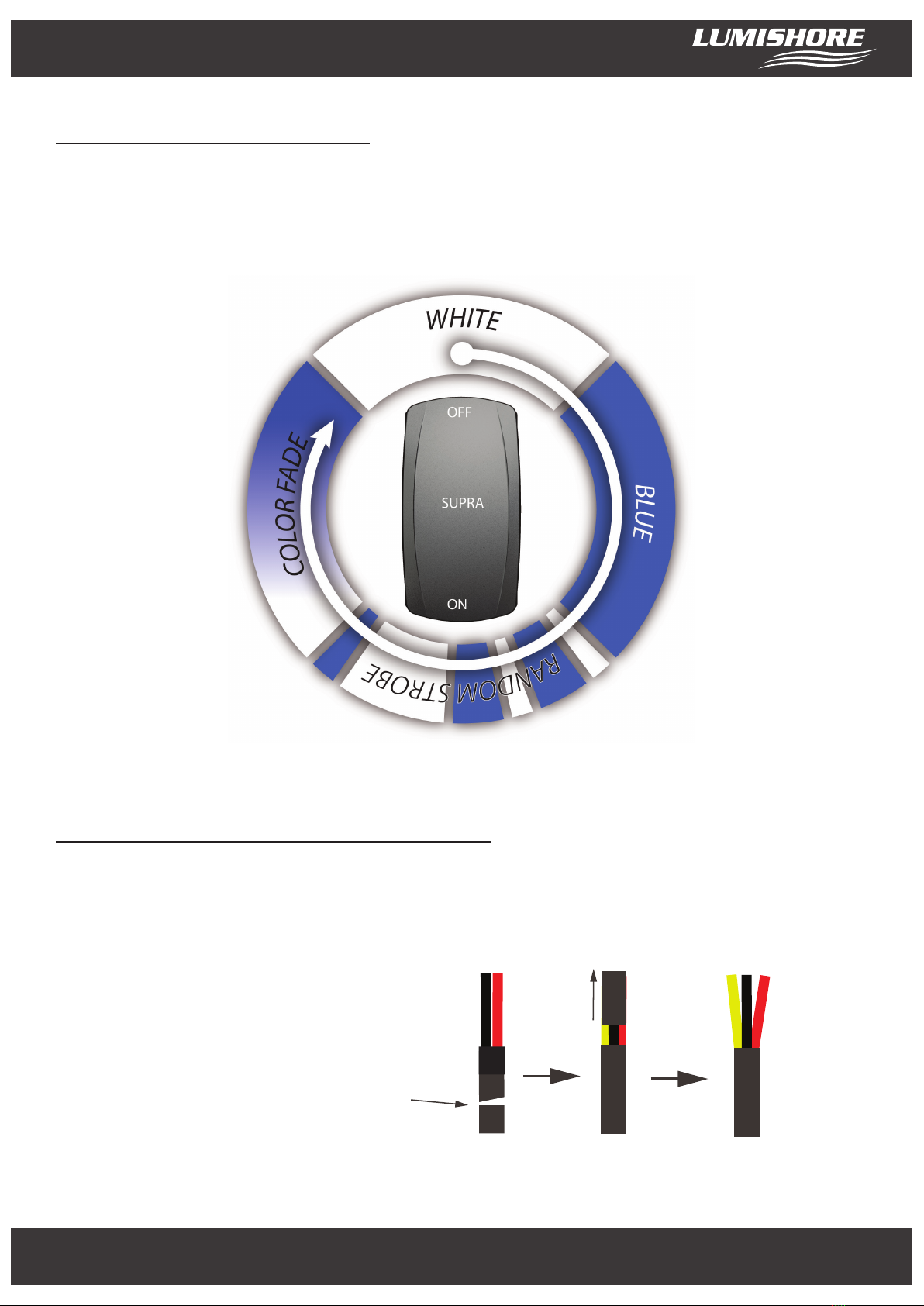
eclipse SMX53 Installation Manual
60-0314 - SMX53 - Blue and White

| + 44(0)208 144 1694 | Info@Lumishore.com
Lumishore USA 7137 24TH Court East Sarasota, Florida 34234 | (941) 405-3302 | Sales@LumishoreUSA.com
Lumishore UK, Unit D12, Upper Fforest Way, Swansea Enterprise Park, Swansea, SA6 8QR
2
Mechanical installaon
Tools: Drill, drill bits, marine sealant (3M 4200, or equivalent),F2 Frearson type screwdriver, Flat head screw
driver, cloth for clean-up:
Pilot Hole for Screws - 9/64” / 3.5mm
Hole for Cable - 9/32” / 7mm
Recess for Gland - 17/32” / 13.5mm hole to a depth of 5/8” / 15mm
1. Select a suitable at surface that is accessible from behind and ensure the cable can be run without a
problem.
2. With one hole at the boom center, mark and drill the pilot holes for the screws & drill a ø4mm
counter bore to a depth of 5mm in each locaon. Drill the power cable hole. The cable hole must be
recessed on the outside of the hull to accept the cable gland on the back of the light, so that the lights
sits ush.
Note: Cored hulls must be sealed prior to ng the lights - refer to the manufacturers instrucons.
3. Clean and prepare the hull ready for the sealant.
Rear side
Basic Dimensions
Apply sealant
Boom center
95mm (3.74in)
12mm
(0.47in)
18mm (0.71in)
PCD 84mm (3.31in)
120°

| + 44(0)208 144 1694 | Info@Lumishore.com
Lumishore USA 7137 24TH Court East Sarasota, Florida 34234 | (941) 405-3302 | Sales@LumishoreUSA.com
Lumishore UK, Unit D12, Upper Fforest Way, Swansea Enterprise Park, Swansea, SA6 8QR
3
4. Apply a connuous thick bead of sealant to the back of the light, making sure the recess on the outer
edge is slightly overlled. Also apply a bead of sealant around the cable gland. Refer to image above.
5. Push the power cable through the hole and align the light with the pilot hole screws.
6. Aach the light using the 3 supplied screws by hand ghtening with a screwdriver.
IMPORTANT: Do not over ghten. Do not use power tools to ghten screws.
7. Use a damp cloth to wipe o excess sealant that has squeezed out around the light. DO NOT use
chemical cleaners or solvents.
IMPORTANT: Refer to the direcons on the sealant to make sure it has fully cured before
launching the boat into the water.
Electrical installaon
There are three control opons for the SMX53 lights, please skip forward to the secon that applies to your
type of installaon.
1. Simple ON/OFF switch - See pages 4 and 5.
2. Eclipse Command Center - See pages 5 and 6.
3. SUPRA Lumi-Hub & Switch (with oponal Supra Bridge for MFD control) – See pages 7, 8, 9, 10 & 11.

| + 44(0)208 144 1694 | Info@Lumishore.com
Lumishore USA 7137 24TH Court East Sarasota, Florida 34234 | (941) 405-3302 | Sales@LumishoreUSA.com
Lumishore UK, Unit D12, Upper Fforest Way, Swansea Enterprise Park, Swansea, SA6 8QR
4
Installaon diagram - Single switch
Plan the cable route prior to installaon. Ensure all cables are suitable for marine applicaons, and
correctly rated for the required voltage and current. Each light must be individually fused. The cable
connecons are:
Red 12V or 24V DC
Black Ground
Fuse rangs: 12V DC 7.5A
24V DC 4A
An ON / OFF switch should be installed to select the modes of operaon. All connecons must be made
waterproof.
Battery / PSU (12 or 24V DC)
Red
(+VDC)
Red
(+VDC)
Black
(GND)
Fuse
Fuse
Switch
O
On
Fuse or
Circuit
Breaker

| + 44(0)208 144 1694 | Info@Lumishore.com
Lumishore USA 7137 24TH Court East Sarasota, Florida 34234 | (941) 405-3302 | Sales@LumishoreUSA.com
Lumishore UK, Unit D12, Upper Fforest Way, Swansea Enterprise Park, Swansea, SA6 8QR
5
Switch operaon - Dual color lights
The lights operate in White, Blue, Random Strobe, and Color Fade modes. To change the mode turn the
switch OFF / ON (within 2 seconds). To reset to White mode, switch the lights o for 5 seconds. The
lights will always come on in White mode when rst switched on.
Electrical installaon - ECLIPSE Command Center
Cut the cable just below the
heat shrink. Remove the outer
insula�on to reveal the yellow
wire
Note: The ECLIPSE control opon requires for an addional step to reveal the Yellow
wire from each SMX light. Please follow the step below.

| + 44(0)208 144 1694 | Info@Lumishore.com
Lumishore USA 7137 24TH Court East Sarasota, Florida 34234 | (941) 405-3302 | Sales@LumishoreUSA.com
Lumishore UK, Unit D12, Upper Fforest Way, Swansea Enterprise Park, Swansea, SA6 8QR
6
More than 2 lights per Command Center
YEL YEL YEL YEL YEL
RED to +10.5 - 15V
Fuse Fuse Fuse Fuse Fuse
RED to +10.5 - 15V RED to +10.5 - 15V RED to +10.5 - 15V RED to +10.5 - 15V
BLK to GND BLK to GND BLK to GND BLK to GND BLK to GND
ECLIPSE Command Center
CONNECT AS BELOW;
ECLIPSE cable harness YEL to SMX53 YEL
SMX53 RED to +10.5-15V (Individually fused)
SMX53 BLK to GND
ECLIPSE Cable
Harness
RED, WHT & BLU - No connect.
Ensure any unused wires are isolated.
Up to 2 lights per Command Center
RED
BLK
YEL
RED
WHT
BLU
YEL
RED
BLK
YEL
ECLIPSE Command Center
CONNECT AS BELOW;
ECLIPSE cable harness RED to SMX53 RED
ECLIPSE cable harness YEL to SMX53 YEL
ECLIPSE cable harness WHT & BLU to SMX53 BLK
ECLIPSE Cable
Harness
10 - 15V
Select and install appropriate
blade fuse for complete circuit
Important! The ECLIPSE Command Center
installation is suitable for 12V boats ONLY.

| + 44(0)208 144 1694 | Info@Lumishore.com
Lumishore USA 7137 24TH Court East Sarasota, Florida 34234 | (941) 405-3302 | Sales@LumishoreUSA.com
Lumishore UK, Unit D12, Upper Fforest Way, Swansea Enterprise Park, Swansea, SA6 8QR
7
Electrical installaon - SUPRA Lumi-Hub
Note: This opon requires a Lumishore SUPRA i-Connect Hub (60-0317) and SUPRA i-Connect Switch
(60-0318). The SUPRA i-Connect Hub is Lumi-Link compable which allows control via cered MFD or
connected device (SUPRA Bridge PN: 60-0368) - See SUPRA Bridge installaon manual for further details.
Plan the installaon rst. Work out where the lights will be mounted. Each light connects to the hub using a
eld installable connector (supplied). One hub can power up to 4 lights, and 4 hubs can be connected
together in one system. The hub should be mounted between the lights and the power source. Plan the
cable routes, including the switch, prior to installaon. Ensure all cables are marine grade, and are correctly
rated for TOTAL current, and voltage.
Warranty
Battery /
PSU
12 or 24 V
Supra Lumi-
Hub
On/Off
Scene
Supra Lumi-Switch
Field Installable
Connectors (Supplied)
Removable
Fuse Cover
Fuse or
Circuit
Breaker

| + 44(0)208 144 1694 | Info@Lumishore.com
Lumishore USA 7137 24TH Court East Sarasota, Florida 34234 | (941) 405-3302 | Sales@LumishoreUSA.com
Lumishore UK, Unit D12, Upper Fforest Way, Swansea Enterprise Park, Swansea, SA6 8QR
8
Note: Four hubs can be connected together. All they need is power connected, and a pre-moulded data
cable run between the hubs (see connecng mulple hubs secon for wiring diagram).
Installing the Hub(s)
1. Select a site for the installaon of the SUPRA i-Connect Hub(s). This should be within reach of the light
cables that will be aached to the hub(s). The hub(s) should be in a dry, well venlated area. The hub(s)
should NOT be mounted in areas prone to ooding or excess heat.
2. The hub(s) should be mounted to a at surface, with room for access to the fuse panel and connectors.
3. Mount the hub(s) as close to the power source as possible. Run the power cable to the hub(s) from the
power source.
4. Remove the clear fuse panel and insert the fuses (supplied):
12V DC 7.5A
24 V DC 4A
Once the fuses are in place replace the fuse panel.
5. Select a posion for the SUPRA i-Connect Switch. Mount the switch and run the cable to the hub. Con-
nect the switch connector to the hub. The switch cable can be extended up to 50m. To extend, cut the
switch cable, and connect in a 18 AWG, 3 core cable of the desired length. Take care to ensure that the
correct conductors are connected together.
6. Add the eld installable connector to the light cables (supplied). The light cables need to be cut back to
reveal the third (data) wire.
Trim back the insulaon on each core to reveal 4mm of wire.
Cut the cable just below the
heat shrink. Remove the outer
insula�on to reveal the yellow
wire

| + 44(0)208 144 1694 | Info@Lumishore.com
Lumishore USA 7137 24TH Court East Sarasota, Florida 34234 | (941) 405-3302 | Sales@LumishoreUSA.com
Lumishore UK, Unit D12, Upper Fforest Way, Swansea Enterprise Park, Swansea, SA6 8QR
9
7. Unscrew the back of the connector to reveal the terminals. Fit the strain relief and gland nut over the
cable BEFORE wiring the connector.
8. Wire the connector as shown below. TAKE CARE to secure the wires well with the grub screws. Check for
any stray strands that could short to the other pins before ng the strain relief and gland nut.
Note: Check the wiring is correct before connecng to the hub. Incorrect wiring can damage the light.
Field Installable
Connector terminals
viewed from cable side
RED
(12 or 24 V DC) BLACK
(Ground)
YELLOW
(Data)
BACK VIEW
BLACK
(Ground) RED
(12 or 24 VDC)
YELLOW
(Data)
FRONT VIEW
9. Fit and ghten the strain relief and gland nut onto the connector. Plug into the hub, taking care to orient
the key correctly. Tighten the cap to make the waterproof seal.

| + 44(0)208 144 1694 | Info@Lumishore.com
Lumishore USA 7137 24TH Court East Sarasota, Florida 34234 | (941) 405-3302 | Sales@LumishoreUSA.com
Lumishore UK, Unit D12, Upper Fforest Way, Swansea Enterprise Park, Swansea, SA6 8QR
10
10. Make sure that any unused ports on the hubs have dust caps ed (supplied)
11. Connect power to the hub and switch on. Make sure the lights are tested, and working as expected
before the boat goes back in the water.
The lights operate in White, Blue, Strobe, Synchronized Strobe, Color Fade mode, and Synchronized Color
Fade mode.
Connecng a second Hub
You will need a second SUPRA i-Connect Hub(s) (60-0317) and DMX extension cables (1m - 60-0403, 5m -
60-0404 or 15m - 60-0405)
Each hub can power up to 4 lights, and up to 4 hubs can be connected together in one system. To add a
second hub follow the diagram on Page 11.

| + 44(0)208 144 1694 | Info@Lumishore.com
Lumishore USA 7137 24TH Court East Sarasota, Florida 34234 | (941) 405-3302 | Sales@LumishoreUSA.com
Lumishore UK, Unit D12, Upper Fforest Way, Swansea Enterprise Park, Swansea, SA6 8QR
11
Supra Lumi- Hub
Field Installable
Connectors (Supplied)
Supra Lumi-Hub
Scene
Field Installable
Connectors (Supplied)
DMX Extension
Cable used to
connect hubs together
Warranty
Battery /
PSU
12 or 24 V
On/Off
Scene
Supra
Lumi-Switch
Fuse or
Circuit
Breaker
Check all ports
without connectors
have dust caps tted
SUPRA Bridge
Module (60-0368)
Optional MFD control
via SUPRA bridge

| + 44(0)208 144 1694 | Info@Lumishore.com
Lumishore USA 7137 24TH Court East Sarasota, Florida 34234 | (941) 405-3302 | Sales@LumishoreUSA.com
Lumishore UK, Unit D12, Upper Fforest Way, Swansea Enterprise Park, Swansea, SA6 8QR
12
Cleaning and maintenance
LUMISHORE lights require simple cleaning. Lights should be checked oen to ensure the light body and lens
area are free from sea growth. In the event that your light requires cleaning, we recommend the use of a
so cloth or so bristled brush.
• DO NOT use any abrasive cleaning materials as these may damage the body of the light.
• DO NOT use any cleaning uids that contain solvents, acids or alkali’s.
• DO NOT clean using pressure washing or sandblasng equipment.
Slight discoloraon of body may occur over life. This does not aect performance, and is not subject to
warranty.
Due to nature and high build quality it may on rare occasions be possible to see small levels of condensa-
on, this is normal for high power LEDs and will disappear aer cooling and does not harm operaon in any
way.
If the lens of the light is covered for any reason, e.g. maintenance, or painng DO NOT switch the lights on
unl the covers are removed.
Warranty
LUMISHORE Ltd warrants the SMX53 to be free from defects in workmanship and materials for a period of
two years, starng from the date of original purchase. Misuse, abuse, improper installaon, neglect, im-
proper shipping, damage caused by disasters such as re, ood, and lightning, installaon by unqualied
personnel, unauthorized repair or modicaon will void this warranty. For the avoidance of confusion and
doubt, non-compliance with all installaon, maintenance and operang instrucons in this document con-
stute non-conformance with warranty terms.
Table of contents
Other lumishore Lighting Equipment manuals

lumishore
lumishore eclipse CL30 User manual

lumishore
lumishore LUX SNL 180 User manual

lumishore
lumishore eclipse SMX94 User manual

lumishore
lumishore Eclipse SMX93 User manual

lumishore
lumishore Curved 20 User manual

lumishore
lumishore EOS Lumi-Link Blackbox User manual

lumishore
lumishore LUX Livewell Light LW25 User manual

lumishore
lumishore LUX Strip Light SL180 User manual

lumishore
lumishore Eclipse SMX23 User manual

lumishore
lumishore LUX Flood Light 18" User manual