we brighten up your life
LUMZ PTE LTD
INSTALLATION MANUAL
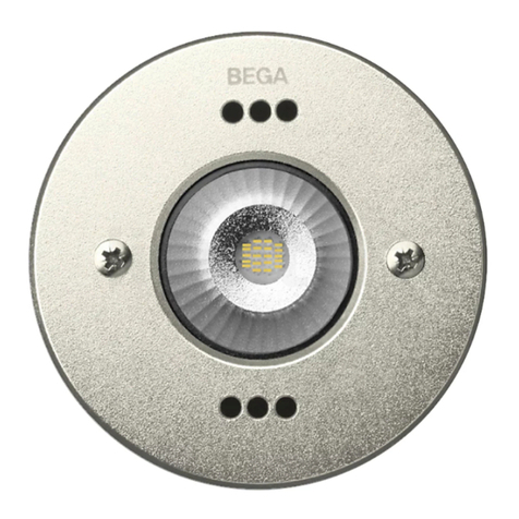
LED MARINO
PRODUCT DESCRIPTION & DIMENSION
MARINO A
MARINO B
MARINO C
MARINO D
WIRING INSTALLATION
MARINO/INSTALLATION MANUAL/REV.2
1/2
Factory:
No.14, Jalan Anggerik Mokara 31/44, Kota Kemuning Seksyen 31,
40460 Shah Alam, Selangor, Malaysia.
Tel: (00603) 5121 1887
Fax: (00603) 5121 5187
Singapore Office (HQ Sales & Marketing):
1 Coleman Street #10-06, The Adelphi,
179803, Singapore.
Tel: (0065) 9758 2771
IP 68 IK 07
MODEL:
www.lumzlighting.com
Connect all wires from the luminaire to AC power using a connector.
Make sure all wiring connecons are ght so that no bare wires are visible.Good connecons may avoid tripping from happening.
For wiring, use a terminal complies with EN 60998-2-1 and EN 60998-2-2.
Consult your local authority regarding disposal or recycling procedures of removed ballast and lamps.
Read the Installaon Manual instrucon carefully before install the products to ensure that you obtain the best possible results.
SAFETY WARNINGS
!
Electronic equipment sensitive to voltage surges.
The installation of a protection device against overvoltages on the electrical
system attenuates the intensity of these phenomena protecting apparatus from
the risk of damage.
Use only flexible cables of suitable diameter according to the national
installation standards.
DO NOT USE HARD CABLES OR ARMOURED CABLES.
Use only supply cables with double case. Do not enter with single cables.
DESCRIPTION
Housing made of cast stainless steel
Impact resistance tempered glass cover
Hard chromeplated body coang
Operang temperature: -20°C~+40°C.
LED lifeme up to 50,000 hours
Voltage range: 24 VDC
Waage: 6, 17, 29 & 46 W
NOTE:
MAKE SURE POWER IS DISCONNECTED UNTIL INSTALLATION OF PRODUCT IS COMPLETELY FINISHED.
FAILURE TO DO SO COULD RESULT IN ELECTRICAL SHOCK CAUSING SERIOUS INJURY OR DEATH.
INSTALLATION INSTRUCTION
Recess Opening Dimension:
Do not use water high pressure cleaners.
The LED module contained in this luminaire SHALL ONLY BE REPLACED by
the manufacturer.
For further informations, please contact your supplier.
The electronic equipment should not be disposed of in the normal waste.
Instead it should be recycled in accordance with the waste electronic &
electrical equipment (WEEE) directive.
Terminal block not included. Installation may require advice from a qualified
person.
The IP rating of the electrical connection must be equal to or greater than the
IP rating of the luminaire.
98
180
205
250
63 83
54 77
55 88
56 79
150
107.3
82.5
120
156
126
179
126
232
OUTER SLEEVE
MARINO A MARINO B
MARINO C MARINO D
# 24V Remote Constant Voltage Driver
Required
Customer supply
<1m
117.30
150
<1m
166
120
<1m
189
126
<1m
242
126
THIS PART
ABOVE SURFACE
MARINO A
MARINO B
MARINO C
MARINO D
Connect wires from the luminaire to DRIVER as follows:
1. Connect
BLUE
/ BLACK wire to the -VE wire.
2. Connect
BROWN
/
RED
wire to the +VE wire.
BROWN / RED (+)
BLUE / BLACK (-)
