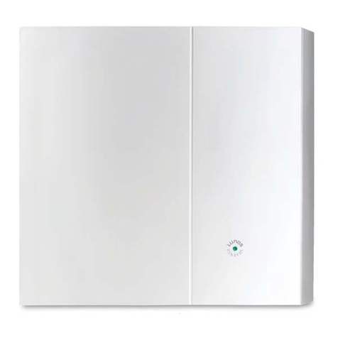
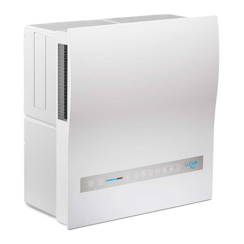
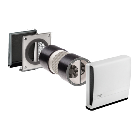
Lunos Silvento ec User manual

1
DE Einbauanleitung
Silvento ec Klemmlüfter
- Bitte an den Nutzer weiterleiten -
EN Installation Manual
Silvento ec Clamp-in Fan
- Please pass on to user -

18
About These Instructions; Safety Instructions, Range of Application, Disposal 18
Technical Data 19
Notes, Shipping units, Installation Examples 20
Installation - Replacement of a Skalar-V and installation
in a wall installation housing 20
Installation - Installation in a wall cutout 20
Installation - Additional modules 21
Electrical Connection 22
Setting the DIP Switches 23
Humidity Control 24
Filter Change, Cleaning, Additional Parts and Replacement Parts 25
Read these instructions carefully and completely before executing assembly work! General safety
instructions and the safety symbols with respective notes in the text must be observed.
These instructions are to be passed on to the user after completing assembly work (tenant, own-
er, building administration etc.).
Symbols in these instructions:
This symbol warns of a risk of injury
This symbol warns of a risk of injury from electricity
Caution! Any installation work on the ventilation unit may only be carried out with the mains
voltage disconnected!
Attention! Electrical connections must be carried out by authorized qual ified staff in
accordance with applicable VDE 0100!
Attention! This device must not be operated by children or persons (filter change/
cleaning) who are not able to operate it safely on account of their physical, sensory or mental
capacity or due to their inexperience or lack of skills.
When using fans for exhaust air operation, a properly working fresh air flow must always be
ensured.
Temperature application range: - 15°C to + 40°C
Can be used at a relative air humidity of up to 75% indoors (non-condensing; temporary exceedance
with the fan running is permissible). The user is requested to switch off the unit if the application
limits are exceeded. Ensure fresh air supply by window ventilation.
Dispose of packaging correctly sorted. If you wish to dispose of the device, observe appli-
cable conditions. Within the framework of the German Electrical and Electronic Equipment
Act (ElektroG), the free return of this device to your municipal collection point is guaran-
teed.
Contents Page:
Installation Instructions EN
About These Instructions
Safety Instructions
Range of Application
Disposal
8

19
Technical Data
Power supply: 200-240 V AC 50/60 Hz
Remote control input: 0-10 V DC
Protection class: II
Protection type: IPX5
Air volume flow: OFF, 15-60/90* m³/h
Electrical power consumption: 1.8-6.2/14.5* W
Sound pressure level: 22-35/44* dB(A)
(with active humidity control „so to say“-stepless between 15 and 69/90* m³/h)
* depending on the control board
Every Silvento ec can be combined with a control board without a humidity sensor or with a humidity
sensor, each control board can be combined with one extension module.
This results in the following configuration options:
The Control board for the basement ventilation 5/EC-KE is optionally available and not listed here.
We will be pleased to inform you.
All units are equipped with class G2 filters and a filter change indicator.
Ventilation units of the "Silvento" series meet all requirements:
- for low voltage (CE) according to EG guidelines (2006/95/EG; 2014/35/EU)
- for electromagnetic compatibility (CE) according to EC directives (2004/108/EC; 2014/30/EU)
The characteristic curve of the level 60 m³/h is part of the DIBt approval Z-51.1-215 and can be taken
from it. The characteristic curve is also summarized with all other characteristic curves in a separate
document that can be downloaded from www.lunos.de.
The fans of the Silvento ec series can be configured in combination with the circuit boards listed
above and the volume flow can be calibrated. Instructions can also be found at www.lunos.de.
The volume flows specified in the accompanying documents refer to the installed condition, taking
into account correct design/planning and corresponding installation.
Function/Control Board 5/EC-ZI (90) 5/EC-FK (90) 5/EC-FK+ (90)
Volume flow base load (DIP 1,2)
Volume flow demand (DIP 6,7)
Switch-on delay (-/45/120s) (/ / )(/ / )( - / - / -)
Follow-up time (-/15/30 min) (/ / )(/ / )( - / - / -)
Interval operation
(-/4h30min/2h15min) (/ / )(/ / )( - / - / -)
Humidity / temperature sensor ( - / - / -)(/ )(/ )
VOC Sensor (smells) - -
CO2 equivalent operation - -
LED filter change indicator
0-10 V control input
Data logging
Optional Radio Module FM-EO or
Motion Detector 5/BM (/ )(/ )(/ )
Diagnostic tool PC based
15/20/30/40/45/45/50/60 (90) m³/h
15/20/30/40/45/45/50/60 m³/h

20
Please check the delivery for completeness and mint condition!
2 Shipping Unit
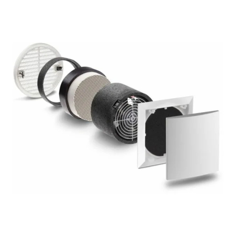
Clamp-in fan unit Silvento KL-EC included:
Grill frame with filter and decor screen
Fan unit with nozzle DN80
Seal (A) (Stick on when replacing Skalar-V)
Snap-in element (B), Mains connection terminal (C)
Installation Manual and Screw accessories
Product data sheet and energy label
The control board (D) is not part of the shipping unit and must be ordered separately.
3 Installation Examples
For fire protection, the shaft wall must have the required fire resitance duration!
If necessary, correct the position of the non-return valve. For possible alignment see 1 Notes.
5 Installation - Installation in a wall cutout
5.1 Connect flextube (DN 80 or DN 75, approx. 50 to 100 cm long) to the main line. Fasten the
sliding connection pipe (F) to the flextube. Seal connections with sealing tape or clamps.
5.2 Make a wall cutout according to the specified dimensions. Installing the pre-wall cladding.
Fix the flextube and power cable ready to hand in the wall opening.
5.3 Remove snap-in element (B) with the mains connection terminal (C) from the fan and attach
the mains connection terminal to the mains cable according to the selected connection dia-
gram (see 6 Electrical connection).
Attention! Disconnect the mains cable from the power supply!
5.4 Plug on and snap in the snap-in element with the mains connection terminal and
connected mains cable.
Attention! The mechanical installation of the power cable must also be voltage-
free! Alternatively, use a flexible cable if necessary!
5.5 Snap-in element with mains connection terminal in place!
5.6 Push the sliding connection pipe in until it reaches the stop (if necessary, correct the position
and fit of the non-return valve, see figure 5.9)! Slide the fan unit into the wall cutout.
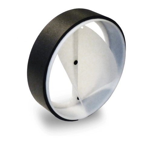
5.7 Position and correction of the non-return valve (important for ceiling installation):
In the installation position, the non-return valve in the exhaust vent must close by its own
weight. The non-return valve can be pulled out inwards for correction.
Pay attention to a correct position according to the drawing.
1 Notes
- Installation in area 1 in bath and shower rooms in accordance with VDE 100 is permissible
- Fan installation for use as extractor hood not permitted

21
5 Installation - Additional modules
One of the optionally available additional modules 5/BM (40082), a motion detector module with
radar sensor or FM-EO (40083), a radio module for communication with other fans or a Smart Home
System) can be plugged in to expand the functionality.To do this, proceed as follows:
5.13 Detach the control board (E) from the grill frame (D). Plug the additional module into the 6-
pin connector under the control board as shown in the illustration. Fasten the control board
again in the grill frame according to step 3.3.
5.14 The vertical and horizontal detection range of the motion detector module is 90°.
Note: After applying the mains voltage to the completed ventilation unit, the LED on the con-
trol board flashes once.
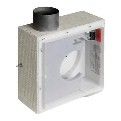
5 Installation - Replacement of a Skalar-V and installation in a wall installation housing
5.15 Glue the enclosed seal (A) onto the exhaust seal of the fan insert and break off guide bars
(see 4 Dimensions (E))
5.16 Slide the fan unit into the wall installation housing, pressing the power cable back into the
shaft.
5.8 The fan unit clamp fan is attached using the clamping screws.
Tighten the clamping screws moderately with a screwdriver.
The automatically extending clamping pieces (H) are positioned from behind on the pre-wall
cladding or in the recesses of the plaster frame of the housings 3/LB, 3/LS, 3/LS 2 and
3/ LB 2.
Screws can be fastened via the flange holes (G) in the plaster frame of the wall installa
tion housing. (Screws + accessories are not included in the delivery)
5.9 Fasten the control board (E) in the provided mounting space of the grille frame (D).
5.10 Connecting the control board to the fan insert.
Ensure that the ribbon cable is routed properly.
5.11 Fasten the grill frame with screw openings KL (marking on the grill frame) on the fan unit.
Insert filter. Put on the front cover and snap it in.
Attention: The grille frame is always mounted according to the mounting position of the fan!
The front cover can then be mounted on the grille frame in two optional positions rotated by
180°!
5.12 With two-room fans: Insert the screen (K) under the filter in the grille frame. The screen for
two-room fans is included in the two-room accessories.

22
Additional installations and electrical components in the ventilation unit are not permitted!
Connection diagrams for further fan functions available on request!
Caution! Any installation work on the ventilation unit may only be carried out with the mains
voltage disconnected! The ventilation unit is insulated in accordance with protection class II, a
protective conductor connection is not required.
Make sure all connection lines are de-energized before connecting the ventilation unit to the
power supply! (Disconnection from power supply with at least 3 mm contact opening, e.g.
fuse)
Each circuit connected to the ventilation system must be fitted with residual current protection
(e.g. RCD switch)!
Electrical connections must be carried out by qualified staff only!
6.1 Automatic operation with humidity control according to DIP switch position of the
control board.
Comfort control: Humidity controlled operation
Basic control: Interval switching possible
6.2 With remote control (0 - 10 V)
The remote control input is divided into two ranges. In the range of 0-5 V the level is
set absolutely, i.e. with highest priority (corresponds to DIP 6,7 with switched L1 ). In the
range of 6-10 V only the base load is set (corresponds to DIP 1,2). In the range of
0-0.4 V the fan operates autonomously.
6.3 Depending on the control board, DIP switch position and module:
With run-on time (basic control): Deactivation of the run-on functions (L2), conti-
nuous operation basic ventilation or OFF according to DIP switches 1 and 2 swit-
chable to regulated ventilation (L1) according to DIP switches 6 and 7
With humidity control (comfort control): Humidity control can be deactivated (L2),
switchable to regulated ventilation (L1)
Note: No light coupling possible with VDE-compliant installation
((R) Bridge)
6.4 Depending on control board, DIP switch position and module:
Single-stage operation, switchable to regulated ventilation
Continuous operation basic ventilation and run-on time-controlled regulated ventila-
tion
Humidity control, switchable to regulated ventilation
Run-on time-controlled regulated ventilation
Note: Use a two-pole switch to switch the room lighting simultaneously with the
regulated ventilation!
6.5 Direct connection to TAC via F+ and F-.
Step 0: 0,6 V - 0,9 V
Step 1: 1,1 V - 1,4 V
Step 2: 1,6 V - 1,9 V
Step 3: 2,1 V - 2,4 V
Step 4: 2,6 V - 2,9 V
Step 5: 3,1 V - 3,4 V
Step 6: 3,6 V - 3,9 V
Step 7: 4,1 V - 4,4 V
Step 8: 4,6 V - 4,9 V
Step 1: 6,1 V - 6,4 V
Step 2: 6,6 V - 6,9 V
Step 3: 7,1 V - 7,4 V
Step 4: 7,6 V - 7,9 V
Step 5: 8,1 V - 8,4 V
Step 6: 8,6 V - 8,9 V
Step 7: 9,1 V - 9,4 V
Step 8: 9,6 V - 9,9 V
Area
absolute
level
Base load
level area
6 Electrical Connection

23
Changing the settings:
1. Remove the front cover
2. Make the desired settings
3. Reassemble in reverse order
The following DIP switch positions with the following functions are available:
Using DIP switches 1, 2, 6 and 7, you can set the air volume flows for basic and regulated ventilation,
and DIP switches 3, 4 and 5 can be used to configure the delay time functions.
DIP switch settings basic ventilation DIP switch settings regulated ventilion
Via the DIP switches (S) on the control board you have the option to set a variety of fan functions!
Each of the white switches has three setting options!
Attention! Only adjust the switch when the ventilation unit is de-energised!
White switch Factory setting 5/EC-ZI, 5/EC-FK:
Basic ventilation: OFF
Nominal load stage: 60 m³/h
Interval: OFF
Run-on time: OFF
Switch-on delay: OFF
Setting the DIP Switches
0 m³/h
15 m³/h
20 m³/h
30 m³/h
40 m³/h
45 m³/h
50 m³/h
60 m³/h
0 m³/h
15 m³/h
20 m³/h
30 m³/h
40 m³/h
45 m³/h
50 m³/h
60 m³/h

24
Interval OFF
Interval ON,
Fan runs every 4 hours for 30 min in regulated ventilation
Interval ON,
Fan runs every 2 hours for 15 min in regulated ventilation
Run-on time OFF
Run-on time ON,
Fan runs on for 15 min in regulated ventilation
Run-on time ON,
Fan runs on for 30 min in regulated ventilation
Switch-on delay OFF
Switch-on delay 120 s
Switch-on delay 45 s
DIP switch sttings interval, run-on time and switch-on delay
Fans equipped with the comfort board 5/EC-FK have an independent humidity control with a stan-
dard control range of 50 - 70 % r.h. controlling between the set basic ventilation stage (DIP switches
1, 2) and the regulated ventilation stage (DIP switches 6, 7). This ensures that the exhaust air volu-
me flow is constantly adjusted to the room air humidity and room temperature, thus achieving an
optimum level of comfort. There is only as much ventilation as necessary, but also only as little as
possible, which saves energy, prevents over-humidification of the apartment and avoids structural
damage and mould.
The control is carried out in a virtually stageless and "intelligent" manner, differentiating between
permanently high relative humidity or rapid increase (e.g. due to showers).
If the relative humidity cannot be significantly reduced within a period of two hours (e.g. in summer),
the fan will be switched to basic ventilation mode.
If the relative humidity increases by more than 5% within one hour during reduced operation mode,
the reduced operation mode will be terminated. If the relative humidity falls below the lower switching
threshold and the basic ventilation level is set to OFF, the fan will be switched off.
If the fan is set to the basic ventilation level OFF, it will run once per hour for 3 minutes at the level of
15 m³/h (sniff mode). If a relative humidity above the set switching threshold, e.g. 50 % RH at 22°C,
is measured during this time, humidity control will be activated.
If the measured relative humidity is lower than the switching threshold, the fan will be switched off
again after these three minutes.
Notes:
If voltage is applied to L2, all special functions, switch-on delay, run-on time, interval operation and
humidity control (5/EC-FK only) will be deactivated.
Within the first two hours after connection to the mains, the fan runs at the level corresponding to
the relative humidity value currently measured .
Humidity Control

25
7.1 The LED lights up continuously when the filter is dirty.
Remove the front cover, remove the filter. Insert a new or cleaned filter. The filter can be
cleaned e.g. using a dishwasher.
Press the button (S) with a tool, e.g. a pen, for 3 seconds; the LED goes out.
Put the front cover back in place.
Never operate the unit without a filter!
When necessary, wipe the front cover and grille frame using a dry soft cloth.
Filter change and cleaning must not be carried out by children or persons who are not able to
operate the unit safely on account of their physical, sensory or mental capacity or due to their
inexperience or lack of skills.
Pack of 3 filters 2/FSI-R Order no.: 39721
Control board basic variant 5/EC-ZI Order no.: 40080
Control board comfort variant 5/EC-FK Order no.: 40081
Control board basic variant up to 90 m³/h5/EC-ZI90 Order no.: 40126
Control board comfort variant up to 90 m³/h5/EC-FK90 Order no.: 40127
Control board comfort variant with VOC sensor 5/EC-FK+ Order no.: 40217
Control board comfort variant with VOC sensor up to 90 m³/h5/EC-FK90+ Order no.: 40221
Control board for basement ventilation 5/EC-KE Order no.: 40133
Motion detector module 5/BM Order no.: 40082
Radio module 5/FM –EO Order no.: 40083
Additional Parts and Replacement Parts
7 Filter Change
Cleaning

26
Notes

27
Notes

28
LUNOS Germany
LUNOS Lüftungstechnik GmbH & Co. KG Phone +49 30 362 001-0
für Raumluftsysteme Fax +49 30 362 001-89
13593 Berlin ∙ Germany www.lunos.de
E187 08.22
Notes
Table of contents
Other Lunos Fan manuals

Lunos
Lunos eGO User manual

Lunos
Lunos RA 15-60 User manual

Lunos
Lunos e2 mini User manual

Lunos
Lunos e2 mini User manual

Lunos
Lunos Silvento V AC User manual

Lunos
Lunos Skalar Series Manual

Lunos
Lunos e2 mini User manual

Lunos
Lunos Silvento EC User manual

Lunos
Lunos EAU 100 User manual

Lunos
Lunos AB 30/60 User manual

Lunos
Lunos fgo User manual

Lunos
Lunos Silvento EC User manual

Lunos
Lunos eGO User manual

Lunos
Lunos Silvento AC Use and care manual

Lunos
Lunos 9/WDS ABL User manual

Lunos
Lunos e2 60 User manual

Lunos
Lunos 3/UP-BR Manual

Lunos
Lunos 9/WDS ABL User manual

Lunos
Lunos eGO User manual

Lunos
Lunos e2 mini User manual