13
Assembly: Assembly t be EN
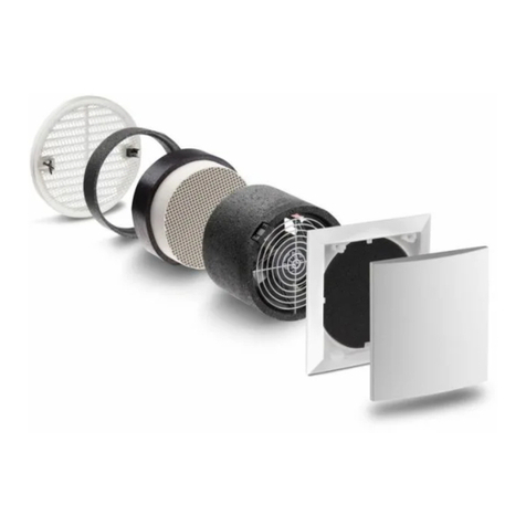
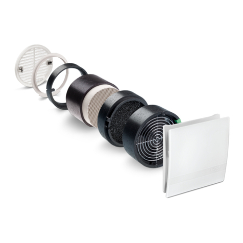
Prepare wall openings for t e assembly tube
(e.g. via core drilling, core bit Ø162 mm). If
necessary, s orten t e tube to t e installation
lengt required (min. 243 mm). In doing so,
ensure t e necessary excess lengt of t e
tube on bot sides to bridge t e plaster
t ickness (after plastering, t e tube must be
flus wit t e plaster or flus wit t e wall or
insulation in t e case of outer grilles to be
plastered). Insert t e tube and seal it all
around (assembly ad esive Order No. 038
733).
①
inside
outside
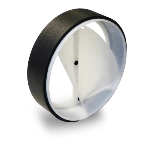
Plaster protection cap
3 mm
Ot er outer grilles available on request!
Apply t e internal and external plaster. In t e
case of an external closure to be plastered,
first replace t e plaster protective cap outside
wit t e external closure.
Remove t e plaster protection cap outside.
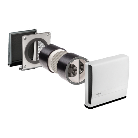
Mount t e outer grille using t e integrated claw
fasteners (tig ten t e screws).
Note:
T e solid plastic outer covers provided by
LUNOS ensure ig resistance to driving rain
and can be used in Stress Group III pursuant
to DIN 4108-3 (2014-11). Metal or metal-
coated covers can be used in Stress Group I
pursuant to DIN 4108-3 (2014-11).
In t e case of buildings exposed to wind or t e
risk of strong winds and rain to t e outer
covers, furt er measures of weat er protection
may be required.
②
➂
inside outside
Tig ten t e claw fasteners wit screws
14
Assembly: Motor nit and electrical connection EN
Slit t e cable duct and tube (2 cm deep).
Only slit t e tube vertically or orizontally!
Insert t e mains cable at an appropriate
lengt into t e tube. Depending on t e lengt
of t e assembly tube, make sure t at t e
mains cable is long enoug to reac t e
connector plug of t e motor!
Slit t e tubes only
in t ese four
sections.
vertically
orizontally
Caution! Any assembly work to t e ventilation device may only be carried out after disconnecting all poles of
t e supply voltage!
Make sure t at t e supply voltage of all connection lines is voltage-free (dead)! (Separation from t e power
supply wit a minimum contact opening of 3 mm, e.g. electric fuse separating all poles).
Eac electric circuit of t is ventilation system must be fitted wit a residual current protection (e.g. FI switc /
RCCB)!
Electrical connection only by a specialist!
Additional installations and electrical components in t is ventilation system are not admissible!
Observe lengt !
Strip and insulate t e connection cable.
T e motor is operated wit 12 V DC. T e
setting of t e airflow levels is carried out via
t e control line (purple). T e motor can also
be operated via several controls supplied by
LUNOS.
All controls are s pplied with installation
man als incl ding connection diagrams!
Mount t e mains cable to t e plug. After
putting toget er t e plug, fix t e connection
by screwing it toget er.
Motorc
able
Mains cable
red blue
purple
Screw toget er!
Safety Instr ctions:
