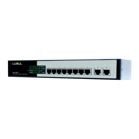
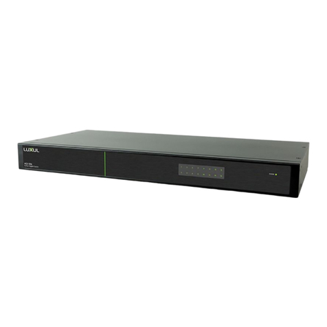
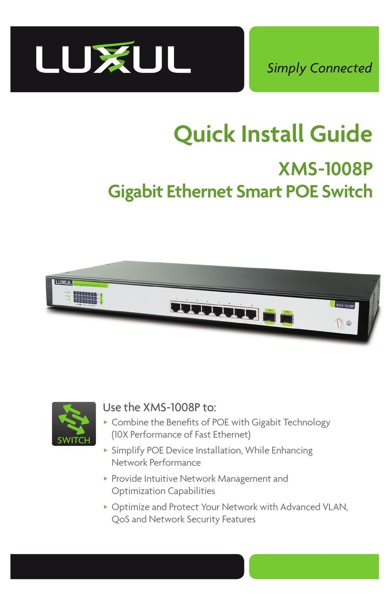
Luxul XMS-1008P User manual

luxul.com
Simply Connected
User Guide
XMS-1008P
Luxul Xen™
Gigabit Ethernet Smart POE Switch
Use the XMS-1008P to:
Combine the Benefi ts of POE with Gigabit Technology
(10X Performance of Fast Ethernet)
Simplify POE Device Installation, While Enhancing
Network Performance
Provide Intuitive Network Management and
Optimization Capabilities
Optimize and Protect Your Network with Advanced VLAN,
QoS and Network Security Features
SWITCH

User Guide
2© Copyright 2011 Luxul. All rights reserved. Trademarks & Registered Trademarks are property of respective holders.
GIGABIT ETHERNET SMART POE SWITCH
MODEL NUMBER: XMS-1008P
USER GUIDE
© 2011 Luxul. All Rights Reserved.
No part of this publication may be modifi ed or adapted in any way, for any
purposes without permission in writing from Luxul. The material in this manual
is subject to change without notice. Luxul reserves the right to make changes to
any product to improve reliability, function, or design. No license is granted, either
expressly or by implication or otherwise under any Luxul intellectual property rights.
An implied license only exists for equipment, circuits and subsystems contained in
this or any Luxul product.
DOCUMENT CONVENTIONS
The following graphical alerts are used in this document to indicate notable situations:
TIP: Tips, Hints or Suggestions to improve performance or Installation.
NOTE: Special requirements that you should take note of.
CAUTION: Care is required. Disregarding a caution can result in data
loss or equipment malfunction.
WARNING!: Indicates a condition or procedure that could result in
personal injury or equipment damage.
CONTACT LUXUL
For sales questions
please contact our
Sales Department
P: (801) 822-5450
If you experience any
problems, please contact
Technical Support
P: (801) 822-5450
E: suppor[email protected]
To check for fi rmware updates or download pre-confi gured application modules,
visit luxul.com.

luxul.com | 357 South 670 West | Suite 160 | Lindon, UT 84042 | p: 801-822-5450 | f: 801-822-5460
User Guide
3
luxul.com | 357 South 670 West | Suite 160 | Lindon, UT 84042 | p: 801-822-5450 | f: 801-822-5460
33
PACKAGE CONTENTS
XMS-1008P Gigabit Ethernet Smart POE Switch
Power cable
Two L-shape brackets and eight matched screws
Four rubber footpads
Quick Install Guide
If any of the listed items are missing or damaged, please contact the reseller from
whom you purchased for return/replacement.
HARDWARE DESCRIPTION
Front Panel
The front panel of the XMS-1008P switch includes 8 1000Mbps RJ45 and 2 SFP ex-
pansion ports on the right side and LED indicators on the left side. Each 1000Mbps
port has one Link/Activity LED, one 1000Mbps LED and one POE LED, there are also
two SFP LEDs, one Power LED, one System LED and a reset button.
XMS-1008P
1357
2468
8-Port Gigabit Ethernet Smart POE Switch
SFP1
SFP2
POWER
SYS
RESET
LINK
ACT
POE
SPEED
1 2 3 4 5 6 7 8
SPEED: 10/100Mbps 1000Mbps
XMS-1008P Front Panel
Status indicators
Each port has one Link/Activity LED, one 1000Mbps LED and one POE LED. In
addition, there are two SFP LEDs, one Power LED, one System LED, as well as a Reset
button to reboot the device or restore factory default settings. The green LED
indicators show the working status of the switch. The following table describes the
LED functionality:
Indicator Name Description
Power On Indicates that there is power to the XMS-1008P
Off If LED is off, check power connections and on/off
switch at the back of the unit.
Link/Act On There is a device connected to the port.
Flashing A port is receiving or transmitting data.
Off There is nothing connected to the port.

User Guide
4© Copyright 2011 Luxul. All rights reserved. Trademarks & Registered Trademarks are property of respective holders.
Indicator Name Description
1000 Mbps On A device capable of 1000Mbps is connected to the port.
Off If a port has no device connected or it is not a 1000
Mbps capable device, the 1000 Mbps LED will be off.
POE On A POE enabled device is connected and being
supplied power
Off No POE enabled device is connected or POE is not
enabled on this port
SYS On Indicates that the XMS-1008P is running normally.
Flashing The XMS-1008P is restoring default settings.
Off The XMS-1008P is in startup and initialization process
or is not on.
At startup, port LEDs will fl ash for 1 second as a self test.
Reset Button
The Reset button (Located at the lower left corner of the front panel) is used to clear the
current settings of the switch and restore factory default settings.
How to Use the Reset Button
To Hard Reset the Switch: With the XMS-1008P powered on, press the Reset
button.
CAUTION: DO NOT hold the button as this will factory default
the switch
To Restore the Default Settings: With the XMS-1008P powered on, press and
hold the Reset button until the status of the System LED shows the follow-
ing: On – fl ashing – off. You can now release the Reset button, and the switch
automatically restores the factory default settings. When the System LED comes
on again, the XMS-1008P will be set to factory defaults.
CAUTION: Please note this will remove any confi guration done to the
switch prior to Reset.
Network Ports
There are 8 10/100/1000Mbps RJ-45 ports (Ports 1~8), that support Auto MDI/MDIX.
Two Gigabit SFP optical/copper module expansion ports with support for hot-
swapping of the SFP modules.

luxul.com | 357 South 670 West | Suite 160 | Lindon, UT 84042 | p: 801-822-5450 | f: 801-822-5460
User Guide
5
luxul.com | 357 South 670 West | Suite 160 | Lindon, UT 84042 | p: 801-822-5450 | f: 801-822-5460
55
NOTE: The SFP expansion ports cannot support optical connections
until equipped with an SFP (Mini GBIC) optical module.
NOTE: When powering up, the port LEDs corresponding to the optical
interface may take a moment to initialize. This is normal as the
XMS-1008P does not detect the optical connection until after
the initialization and startup of internal software systems are
completed.
TIP: To extend your wired network connections beyond 300 feet, an
optical connection will be required. Please contact your Luxul
representative or go to our website to learn more about optical
fi ber, SFP optical modules and optical network installation.
Rear Panel
The rear panel provides an AC input socket and power on/off switch. Use the
included power cable to connect the XMS-1008P to a surge protected outlet. The
built-in high-performance switching power supply of the XMS-1008P supports an
input range of: AC 100 V ~ 220V, 50 Hz ~ 60 HZ.
INSTALLATION PREPARATION
System and Environmental Requirements
Network cables to connect the XMS-1008P to Ethernet enabled devices
A computer supporting TCP/IP and equipped with a Web browser. Supported
Web browser versions include Microsoft IE 7.0 and up, Safari 1.0 and up or Mozilla
Firefox 1.0 and up. The Web browser is used to confi gure the XMS-1008P.
Power must be AC 100V ~ 220V, 50Hz ~ 60Hz.
Temperature of the operating environment should be: 32F~113F (0C~45C). Place
the switch away from heat generating devices. For best performance and heat
dissipation/ventilation, make sure there is adequate space around the switch.
Humidity of the operating environment should be: 5%-95% non-condensing. Do
not place the switch in an extremely dirty or damp location.
Keep the switch away from strong electromagnetic fi elds (i.e. Air Conditioner
compressors, fl uorescent light ballasts, CRT monitors/televisions, etc.), and free
from vibration, dust and direct sun light.
3.2 Before Connecting to the Network
The XMS-1008P can be rack-mounted or used as a desktop switch. Before con-
necting to the network, please be aware of the following requirements:
User Guide
6© Copyright 2011 Luxul. All rights reserved. Trademarks & Registered Trademarks are property of respective holders.
Install the XMS-1008P in a stable/safe place to avoid any possible damage
Make sure there is adequate space around the XMS-1008P for adequate ventila-
tion and proper heat dissipation. It is recommended to have at least 4-6 inches
around all sides.
Do not place heavy articles on the XMS-1008P.
Power outlets should be within 5 feet of the XMS-1008P.
Verify the ground connection of the outlet is functioning properly.
Check the power cord to confi rm a secure connection.
Avoid placement in direct sunlight.
When installing the XMS-1008P on a fl at surface, attach the rubber feet to the
bottom of the device to avoid scratching the surface.
XMS-1008P INSTALLATION
Installation on Desktop/Shelf
As shown below, attach the four rubber footpads to 4 corner indentations on the
bottom of the XMS-1008P. Place the switch horizontally on a solid, level platform.
Desktop/Shelf Installation of XMS-1008P
Installation in a Rack
The XMS-1008P is suitable for 19-inch rack installation. With the included L brack-
ets, it can be conveniently installed into a server or audio rack. As shown below, use
three screws to attach the L-shaped brackets on either sides of the XMS-1008P, and
horizontally insert the switch into a free space within the rack. Use your desired
hardware to affi x the switch supports to the rack.
L-Shaped Supports for XMS-1008P

luxul.com | 357 South 670 West | Suite 160 | Lindon, UT 84042 | p: 801-822-5450 | f: 801-822-5460
User Guide
7
luxul.com | 357 South 670 West | Suite 160 | Lindon, UT 84042 | p: 801-822-5450 | f: 801-822-5460
77
Network Connections
The XMS-1008P supports 10/100/1000 Mbps Ethernet; 10/100 Mbps half/full-
duplex mode and 1000 Mbps full-duplex mode. All RJ-45 ports support Auto MDI/
MDIX and can be used as ordinary ports or as Uplink ports. Any RJ-45 port can be
used to connect the XMS-1008P to an Ethernet enabled device (including servers,
routers, and other switches) without a crossover cable.
The XMS-1008P offers 2 SFP optical/copper module expansion ports. When
Gigabit SFP optical modules are inserted, these interfaces can support optical fi ber
cables to extend the Gigabit network up to 49 miles—enabling the network to
extend beyond the 300 foot limitation of twisted pair Ethernet. When Gigabit SFP
copper modules are inserted, the standard Ethernet limitations apply.
Network Transmission Media
For the RJ-45 ports, Category-5, super Category-5 or Category-6 unshielded twisted
pair (CAT5/CAT5e/CAT6 UTP) should be used. For best results, it is recommended
that Category-6 shielded twisted pair be used to ensure stable data transmission at
1000 Mbps. Optical fi ber/cable should be selected based on the wavelength of the
SFP optical module to be used.
CAUTION: Make sure only one Uplink channel exists between switches
or between the XMS-1008P and a router. Otherwise, loops
can occur and result in network failure.
CONFIGURATION
Login
The XMS-1008P is not equipped with internal DHCP server. However, if you are
connecting to the XBR-2300 Enterprise Dual-WAN Router with the default LAN
address, the confi guration will be automatic. Otherwise, the IP address of the
computer for login and confi guration will need to be manually confi gured. The
table below lists the default parameters of the XMS-1008P.
Parameter: Default Value
Default IP address: 192.168.0.3
Default user name: admin
Default password: admin
Login to the switch with the following steps:
1. Plug an Ethernet cable into any of the switch ports
2. Plug the other end into the Ethernet port of your computer

User Guide
8© Copyright 2011 Luxul. All rights reserved. Trademarks & Registered Trademarks are property of respective holders.
3. Power on the switch.
4. Check to see that the IP address of the computer is within this network seg-
ment: 192.168.0.xxx (“xxx” ranges 2~254. For example, 192.168.0.50). For IP address
settings, refer to Appendix 2.
5. Open the Web browser and enter 192.168.0.3. The switch login window ap-
pears, as shown below.
6. Enter the user name and password (default user name and default password are
both set as “admin”), and then click “OK” to login to the switch confi guration
window.
Click any menu item on the left to view and/or modify the corresponding settings
or functions.
ADVANCED SETTINGS
For login and advanced settings information see the User Guide on luxul.com
FCC Statement:
This equipment has been tested and found to comply with the limits for a Class
A digital device, pursuant to part 15 of the FCC Rules. These limits are designed to
provide reasonable protection against harmful interference in a residential instal-
lation. This equipment uses and can radiate radio frequency energy, and if not
installed and used in accordance with the instructions may cause harmful interfer-
ence to radio communications. However; there is no guarantee that interference
will not occur in a particular installation. If this equipment does cause harmful
interference to radio or television reception, which can be determined by turning
the equipment off and on, the user is encouraged to try to correct the interfer-
ence by one or more of the following measures:
Reorient or relocate the receiving antenna.
Increase the separation between the equipment and receiver.
Connect the equipment into an outlet on a circuit different from that to which
the receiver is connected.
Consult the dealer or an experienced radio/TV technician for help.
Other manuals for XMS-1008P
2
Table of contents
Other Luxul Switch manuals

Luxul
Luxul AMS-1816P User manual

Luxul
Luxul XMS-1010P User manual

Luxul
Luxul XFS-1816P User manual

Luxul
Luxul AMS-2600 User manual

Luxul
Luxul AMS-2624P-E User manual

Luxul
Luxul SW-610-24P-R-A User manual

Luxul
Luxul XMS-2624P User manual

Luxul
Luxul XMS-1024P User manual

Luxul
Luxul AMS-1208P User manual

Luxul
Luxul AMS-4424P User manual

Luxul
Luxul XMS-1024P User manual

Luxul
Luxul XMS-5248P User manual

Luxul
Luxul XFS-1084P User manual

Luxul
Luxul Xen XGS-1008 User manual

Luxul
Luxul XVS-F5 User manual

Luxul
Luxul AGS-1016 User manual

Luxul
Luxul XGS-1008P User manual

Luxul
Luxul XFS-1084P User manual

Luxul
Luxul XMS-1008P User manual

Luxul
Luxul Xen XGS-1008 User manual