LYSAGHT SINGLE CARPORT Instructions for use

SINGLE
CARPORT
10 STEP CONSTRUCTION GUIDE
FOR FREESTANDING CARPORTS
6.125M X 2.85M
CYCLONIC AREAS

2
SINGLE CARPORT
CYCLONIC
SINGLE CARPORT CONSTRUCTION
Building a carport using LYSAGHT®steel products offers clear advantages for both the builder and
homeowner alike. Construction is made easier with dimensionally accurate and quality components joined
using custom made connectors.
STEP BY STEP GUIDE FOR THE PERFECT CARPORT PROJECT
For the homeowner, long term enjoyment is assured with the pre-
painted, corrosion resistant materials.
As with all building materials there are some particular things you
should keep in mind to ensure you get the full benefits of using
LYSAGHT®steel building products.
PACK SIZE AND WEIGHT
Pack size approximately 6200mm (L) x 800mm (W) x 50mm (H).
Pack weight approximately 180kg for single carports and 280kg for
double carports.
Find a level area in your front or back yard and place all of the
delivered components so they are identifiable. Extra fasteners are
included in addition to actual quantities required to build
the carport.
Check the following components off against the bill of materials
from the Lysaght delivery receipt.
FIRMLOK®F100 beam (x4) (F100)
FIRMLOK®F150 beam (x2) (F150)
FIRMLOK®brackets 100mm (x8) (CONB100)
FIRMLOK®brackets 150mm (x4) (CONB150)
Gutter (x1) Gutter stop-ends (x2)
(pair)
Cuphead bolt M8 x 60mm (FBC60) Cuphead bolt M8 x 110mm (FBC110) Metal Tek®14-10 x 150mm (FT150N)
Metal Tek®12-14 x 50 (FT50M) Metal Tek®12-14 x 20 (FT20M) Metal Tek®12-14 x 50 (FT50-WCA with
EPDM and cyclonic washer)
3.2mm Rivet (FR72)
Steel post (x4) (PS90) SPANDEK®0.42mm (x4 sheets) (RS3) Gutter fascia strap (x4) (GSTRAP)
Roof sign (x1) (LABEL) Silicone (x1) (SILIC) Barge capping 0.55mm (x3) (BC1)
OR WALKING
Warranty Void If Removed
NO STANDING
ON ROOF
SILICONE
(CLEAR)
Note: Downpipes and nozzles are supplied separately.
STEP 1 - component check
150mm
100mm

3SINGLE CARPORT
CYCLONIC
STEP 5 - laying out the beams
Using the drawing, lay the beams close
to the point where they will be assembled.
INTERMEDIATE PURLIN
You will have two FIRMLOK®F100
beams that are longer – these are your
intermediate purlins.
HEAD BEAMS
You will have two FIRMLOK®F100 beams
that are shorter in length – these are your
head beams.
RETURN BEAMS
You will have two FIRMLOK®F150 beams –
these are your return beams.
Steel post
Steel post
Steel post
Steel post
Head beam (F100)
Head beam (F100)
Return beam (F150)
Intermediate purlins (F100)
Return eam (F150)
Do
wnpipe Gutter
Fall
FRAME ASSEMBLY
STEP 3 - before you start!
It is recommended that all LYSAGHT®carports are assembled and
installed under the supervision and direction of a person with some
level of building experience.
Safety is of utmost importance at all times. Always make sure that
even basic construction tasks are done utilising safe building
practices.
It is very important to read both the installation instructions and
the supplied construction drawing. They should both be referred
to in preparation for the installation and at every step during the
construction process.
Every dimension, hole location and level should be double
checked for good measure before cutting, fixing, screwing or
bolting to any structural component.
Your carport is designed to resist wind uplift and the footing size
is based on the wind classification. If in doubt, go to the Lysaght
website (www.lysaght.com) and use the wind classification system
to check the design wind speed or seek expert advice to ensure
correct wind classification is selected.
If you do not have the necessary tools or know-how, please
contact your local Lysaght branch for guidance.
STEP 4 - marking out the carport position
Use in-ground stakes and tie up string lines to position the steel
post locations referring to the construction drawing. Check
diagonals are equal for a square shape.
FIRMLOK®beams and SPANDEK®sheeting lengths are reliant upon
these measures being 100% accurate.
Check depth and width of the footing according to the
construction drawing and remove soil.
Mark and cut posts to length and prepare the bottom of
the posts as per the construction drawing with intersecting
fixings and add the connectors to the top of the posts.
Ensure the footings holes are aligned and the final intended
locations of posts correct in accordance with the construction
drawing. Slopes of the ground will need to be taken into
consideration to ensure holes are dug to appropriate depth
and posts are subsequently aligned in terms of height.
Once the digging is complete, simply place bricks/pavers squarely
in the bottom of each hole so the posts can be positioned on solid
ground.
Place the posts in the holes and clamp off in position and brace
with a fall towards the end at which the gutter system will be
positioned. The fall needs to be a minimum 30mm for every 1m in
length.
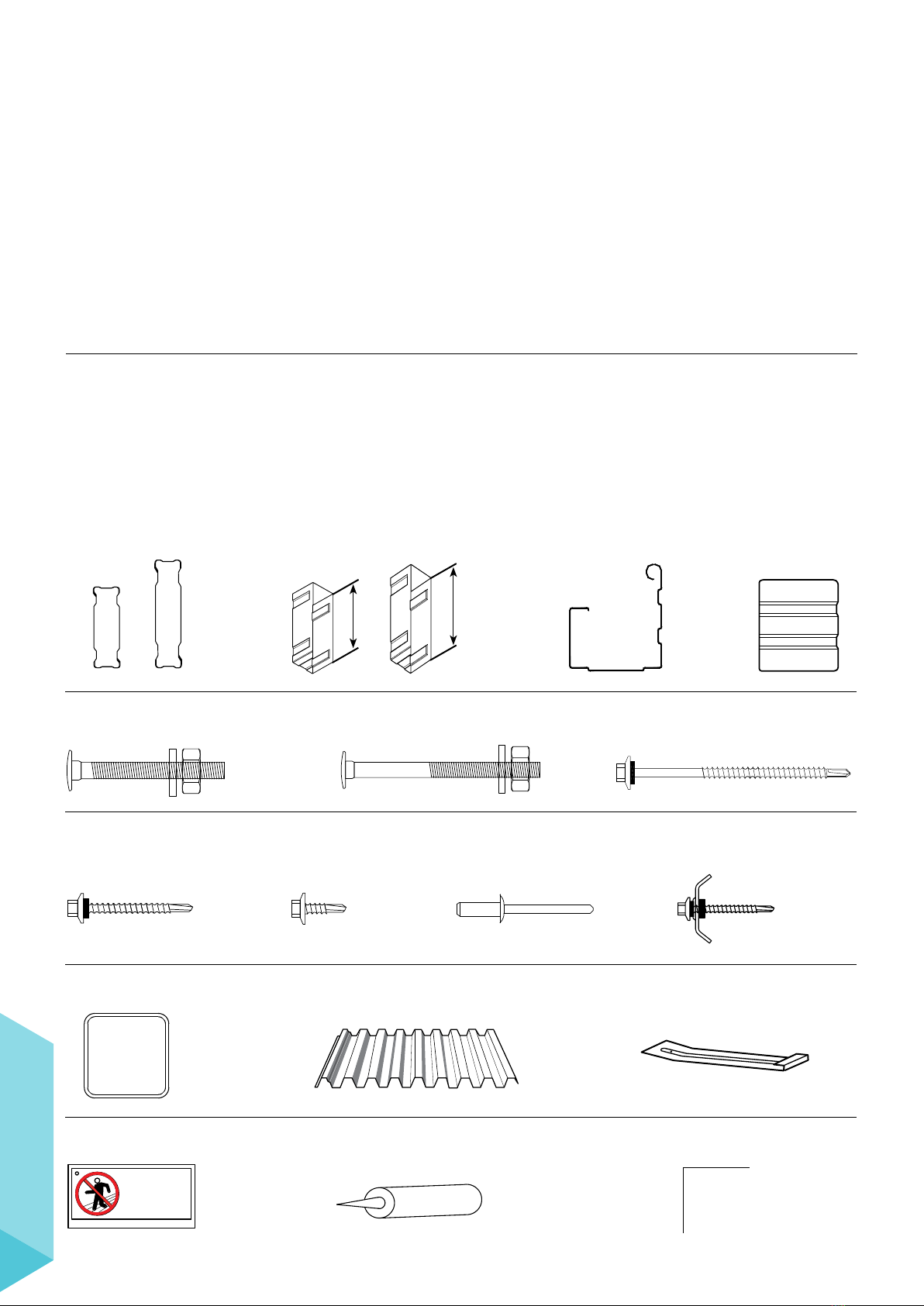
STEP 2 - what tools & materials do you need?
• Step ladder
• Hack saw
• Tape measure
• Pliers and tin snips
• Angle grinder
• Spirit or laser level
• Rivet gun
• Post hole digger or shovel
• PVC downpipe & strap
• Electrical lead
• PVC downpipe elbow
• Silicone gun & clear silicone
• String line/ stakes
• Ratchet wrench
• Safety equipment (PPE)
• Adjustable stands (props)
and clamps
• Adjustable spanner
• Bags of concrete
• Drill & adaptors
• Saw horses and planks

4
SINGLE CARPORT
CYCLONIC
STEP 6 - assembling the frame and posts
HEAD AND RETURN BEAMS -
CONNECTION TO POSTS
Place the head beams on adjustable stands (props) and level the
front and rear head beams at the correct height, also ensuring
you have the correct fall. The FIRMLOK®beam ends sits inside the
connectors.
INTERMEDIATE PURLIN -
CONNECTION TO RETURN BEAMS
The universal beam connectors are fixed to the return beams using
the appropriate fasteners at points 1/3 of the length of the return
beams. The FIRMLOK®beams sit inside the connectors. Note that
the connectors for the intermediate purlins should be fixed to the
return beams before they are lifted up to the posts.
With the framework now in place, double check every
dimension against the construction drawing provided and
check the diagonals for good measure.
See step 8 for determining the final width of the structure to see
if the sheeting width measured in Step 8 is bigger than the
drawing width.
There is tolerance in each of the head beam connectors in case you
need to make the structure slightly wider.
With the measurements checked you can now fix through the
beam connectors to complete frame assembly.
Beams
Post
Connector
Connector
Beams
Connector
Embedment 400mm minimum
Concrete 15mm slope
to ground level
Cover 100
Bottom of
post
Bottom of concrete
Concr
ete
footing
Fixings set in
intersecting pattern
100mm from
bottom of post
Post
Width typically
300mm square
STEP 7 - fixing the posts
Mix the concrete as per manufacturers instructions and pour into
holes, ensuring posts are plumb in both directions.
The concrete should be finished slightly raised at the post,
ensuring water runs away from the post.
Leave overnight or until concrete has fully cured and posts
are firmly fixed in place.
The props can now be removed.

5SINGLE CARPORT
CYCLONIC
Sheeting
Gutter fixing bolt
FIRMLOK®beam
Gutte
r
Gutter strap
Gutter
Outlet
(not supplied)
Stop end
Silicone
STEP 9 - gutter installation
Proceed to attach both ends of the gutter with end stops using the
specified fixings. Silicon seal to ensure a waterproof finish.
Measure the hole at the lower end of the gutter to suit the size
of the downpipe nozzle. Install by using specified fixings and seal
with silicone.
Make certain the hole lines up with the post where the
downpipe will go.
Fix the gutter to the head beam with appropriate bolts evenly
spaced as specified on the construction drawing. Make certain the
fall is to the intended position of the downpipe.
Please note that you will be required to provide a suitable
nozzle and downpipe and fix this according
to the manufacturer’s instructions.
Complete installation of the gutter by attaching the
provided gutter straps with the specified fixings at the
correct spacings according to the construction drawing.
STEP 10 - barge cappings
As a final step, install barge capping material on the
remaining 3 sides of the carport.
The side capping should be attached first – utilising
the specified fixings in the construction drawing at
the appropriate spacings.
The capping should be attached to the sides of the
roof sheeting profile so it sits flush as per diagram.
With the side capping now attached, the top capping
should be fixed through the crests on the roof sheeting
at the same spacing as specified for the side capping.
Silicon seal at overlap of capping.
FIRMLOK®beams
Bar
ge
capping
Roof sheeting
Beam connector
Fixing through
every second rib
Fixing Screw at
1200mm spacings
STEP 8 - roof sheeting
Lay the SPANDEK®roof sheeting from one side of the structure to
the other on the ground and measure the overall width. Check this
against the width on the drawing.
The diagram below indicates the correct laying direction and
details the lapping necessary to ensure correct installation of
roofing material.
You must lay the first sheet at the opposite side of the
prevailing wind direction to ensure lapping is protected
from conditions.
Fix each sheet in place as you move along the structure as
stipulated in the construction drawing provided.
Start each new sheet in this fashion until the whole structure
is covered.
Be careful not to over-tighten the screws as this will crush the ribs
and spread the sheet wider.
Prevailing wind direction
Sheet laying direction

Notes


FOR YOUR NEAREST SUPPLIER VISIT:
WWW.LYSAGHT.COM
FOR SALES ENQUIRIES CALL 13 30 38
FOR TECHNICAL ENQUIRIES CALL 1800 641 417
© BlueScope Steel Limited 18 October 2016.
® product and colour names are registered trade marks of BlueScope Steel
Limited. ™ product and colour names are trade marks of BlueScope Steel
Limited ABN 16 000 011 058. The LYSAGHT®range of products is
exclusively made by BlueScope Steel Limited trading as Lysaght.
PRODUCT DESCRIPTIONS
• All descriptions, specifications, illustrations, drawings,
data, dimensions and weights contained in this catalogue,
all technical literature and websites containing information
from Lysaght are approximations only. They are intended
by Lysaght to be a general description for information
and identification purposes and do not create a sale by
description. Lysaght reserves the right at any time to:
(a) supply Goods with such minor modifications from
its drawings and specifications as it sees fit; and
(b) alter specifications shown in its promotional
literature to reflect changes made aer the date
of such publication.
DISCLAIMER, WARRANTIES
AND LIMITATION OF LIABILITY
• This publication is intended to be an aid for all trades
and professionals involved with specifying and
installing Lysaght products and not to be a substitute for
professional judgement.
• Terms and conditions of sale available at local Lysaght
sales offices.
• Except to the extent to which liability may not lawfully
be excluded or limited, BlueScope Steel Limited will
not be under or incur any liability to you for any direct or
indirect loss or damage (including, without limitation,
consequential loss or damage such as loss of profit or
anticipated profit, loss of use, damage to goodwill and
loss due to delay) however caused (including, without
limitation, breach of contract, negligence and/or breach
of statute), which you may suffer or incur in connection
with this publication.
LYT0006 18.10.16
Table of contents
Popular Shelter manuals by other brands

Palram
Palram Feria 4x4.2 Assembly instructions

Landscape Forms
Landscape Forms Kaleidoscope smart shelter Installation and maintenance manual

Vikre Handel AS
Vikre Handel AS SS305018 Assembly instructions

Vikre Handel AS
Vikre Handel AS JIT-2359J Assembly manual

No Butts Bin
No Butts Bin SR1551 Assembly instructions

X-METAL
X-METAL 13457 Assembly instructions