manuals.online logo
Brands
  1. Home
  2. •
  3. Brands
  4. •
  5. M-system
  6. •
  7. Control Unit
  8. •
  9. M-system 61A User manual

M-system 61A User manual

Other M-system Control Unit manuals
M-system R3-AR4 User manual

M-system

M-system R3-AR4 User manual

M-system R7C-YS2 User manual

M-system

M-system R7C-YS2 User manual

M-system R8-DCM16ALK User manual

M-system

M-system R8-DCM16ALK User manual

M-system R7L-EC16B User manual

M-system

M-system R7L-EC16B User manual

M-system R7M-MS4 User manual

M-system

M-system R7M-MS4 User manual
M-system R7C-EA16/UL User manual

M-system

M-system R7C-EA16/UL User manual

M-system 61F User manual

M-system

M-system 61F User manual

M-system R7D-MS4 User manual

M-system

M-system R7D-MS4 User manual

M-system R7F4HML3-D-DAC32A User manual

M-system

M-system R7F4HML3-D-DAC32A User manual

M-system R3-AV4 User manual

M-system

M-system R3-AV4 User manual

M-system R7ML-YV2-R User manual

M-system

M-system R7ML-YV2-R User manual

M-system R7ML-EC16B User manual

M-system

M-system R7ML-EC16B User manual

M-system M8YC User manual

M-system

M-system M8YC User manual

M-system R7D-DA16 User manual

M-system

M-system R7D-DA16 User manual

M-system R8-FS16N User manual

M-system

M-system R8-FS16N User manual

M-system R7C-EC8A/UL User manual

M-system

M-system R7C-EC8A/UL User manual

M-system Devicenet R7F4HD-DAC32D User manual

M-system

M-system Devicenet R7F4HD-DAC32D User manual

M-system R8-NECT1 User manual

M-system

M-system R8-NECT1 User manual
M-system R30YS4 User manual

M-system

M-system R30YS4 User manual

M-system R8-SVT8 User manual

M-system

M-system R8-SVT8 User manual

M-system R7M-DC16A User manual

M-system

M-system R7M-DC16A User manual

M-system Mini-M M2ADS User manual

M-system

M-system Mini-M M2ADS User manual

M-system R30CT4E User manual

M-system

M-system R30CT4E User manual
M-system R7ML-YV2 User manual

M-system

M-system R7ML-YV2 User manual

Popular Control Unit manuals by other brands

Seitz 14A80 user manual

Seitz

Seitz 14A80 user manual

Wilo RS485 Installation and operating instructions

Wilo

Wilo RS485 Installation and operating instructions

Becker CentralControl CC41 Commissioning Instruction

Becker

Becker CentralControl CC41 Commissioning Instruction

SICK CDB650 operating instructions

SICK

SICK CDB650 operating instructions

Panduit NetKey NKP5E88M Series installation instructions

Panduit

Panduit NetKey NKP5E88M Series installation instructions

MX Options Concentric Petite Fitting instructions

MX

MX Options Concentric Petite Fitting instructions

Clean Water Systems Fleck 2510 Installation & start?up guide

Clean Water Systems

Clean Water Systems Fleck 2510 Installation & start?up guide

Fairchild FSB44104A user guide

Fairchild

Fairchild FSB44104A user guide

LEGRAND Wattstopper LMIN-104 installation instructions

LEGRAND

LEGRAND Wattstopper LMIN-104 installation instructions

PMK ATT10BNCS instruction manual

PMK

PMK ATT10BNCS instruction manual

Tektronix TDS3FFT user manual

Tektronix

Tektronix TDS3FFT user manual

Woodward easYgen Technical manual

Woodward

Woodward easYgen Technical manual

Balluff BNI EIP-502-105-R015 user guide

Balluff

Balluff BNI EIP-502-105-R015 user guide

NXP Semiconductors TWR-LS1021A Getting started

NXP Semiconductors

NXP Semiconductors TWR-LS1021A Getting started

Advantech PCM-3117 Startup manual

Advantech

Advantech PCM-3117 Startup manual

Danfoss MCO 101 manual

Danfoss

Danfoss MCO 101 manual

Moons' Lin Engineering R701P user manual

Moons'

Moons' Lin Engineering R701P user manual

Aventics RV1 operating instructions

Aventics

Aventics RV1 operating instructions

manuals.online logo
manuals.online logoBrands
  • About & Mission
  • Contact us
  • Privacy Policy
  • Terms and Conditions

Copyright 2025 Manuals.Online. All Rights Reserved.

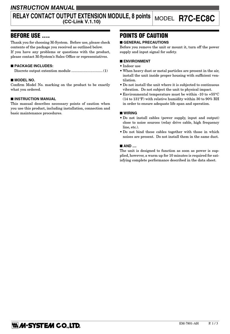
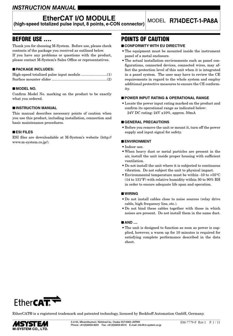
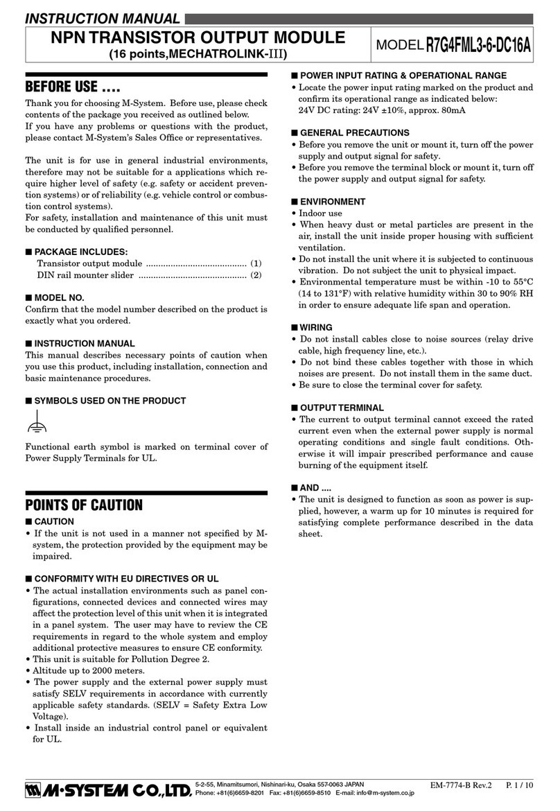
BEFORE USE ....
Thank you for choosing M-System. Before use, please check
contents of the package you received as outlined below.
If you have any problems or questions with the product,
please contact M-System’s Sales Office or representatives.
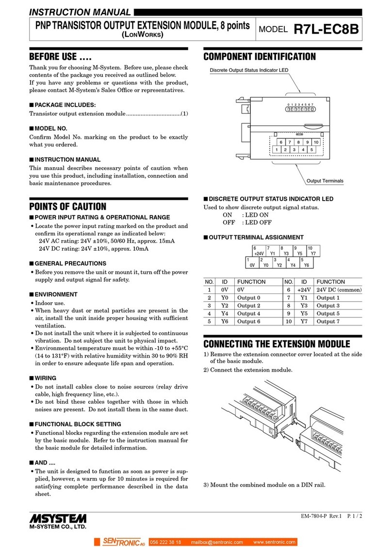
■PACKAGE INCLUDES:
Analog I/O module ..............................................................(1)
■MODEL NO.
Confirm Model No. marking on the product to be exactly
what you ordered.
■INSTRUCTION MANUAL
This manual describes necessary points of caution when
you use this product, including installation, connection and
basic maintenance procedures.
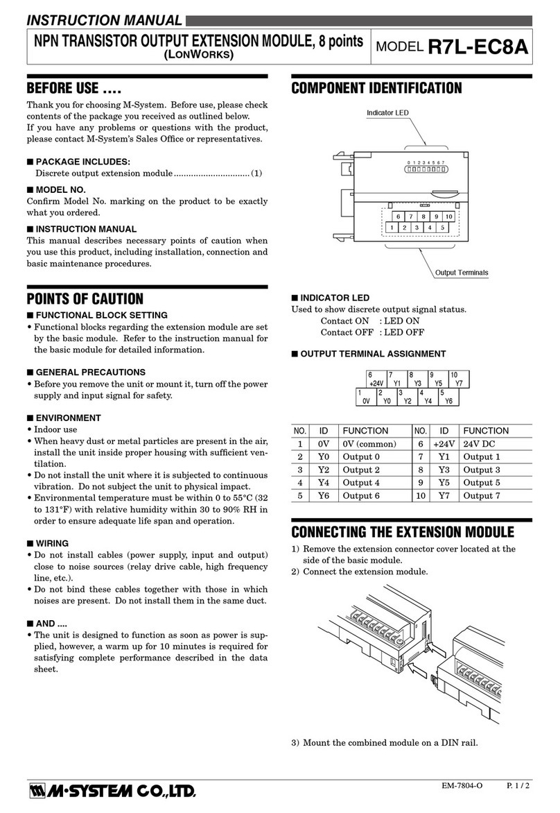
POINTS OF CAUTION
■POWER INPUT RATING & OPERATIONAL RANGE
• Locate the power input rating marked on the product and
confirm its operational range as indicated below:
85 – 132V AC rating: 85 – 132V, 47 – 66 Hz, approx. 4VA
24V DC rating: 24V ±10%, approx. 4W, approx. 160mA
■GENERAL PRECAUTIONS
• Before you remove the unit or mount it, turn off the power
supply, input signal and output signal for safety.
■ENVIRONMENT
• Indoor use.
• When heavy dust or metal particles are present in the
air, install the unit inside proper housing with sufficient
ventilation.
• Do not install the unit where it is subjected to continuous
vibration. Do not subject the unit to physical impact.
• Environmental temperature must be within -5 to +55°C
(23 to 131°F) with relative humidity within 30 to 90% RH
in order to ensure adequate life span and operation.
■WIRING
• Do not install cables close to noise sources (relay drive
cable, high frequency line, etc.).
• Do not bind these cables together with those in which
noises are present. Do not install them in the same duct.
■AND ....
• The unit is designed to function as soon as power is sup-
plied, however, a warm up for 10 minutes is required for
satisfying complete performance described in the data
sheet.
INSTALLATION
Use the Installation Base (model: MxBS2).
ANALOG I/O MODULE
(conforms to AnyWire wiring saving system) MODEL 61A
5-2-55, Minamitsumori, Nishinari-ku, Osaka 557-0063 JAPAN
Phone: +81(6)6659-8201 Fax: +81(6)6659-8510 E-mail: info@m-system.co.jp
EM-6639 Rev.2 P. 1 / 3
INSTRUCTION MANUAL
COMPONENT IDENTIFICATION
Body
Specifications
■FRONT PANEL CONFIGURATION
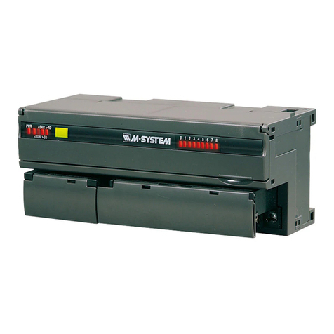
PWR
RDY
LINK
1
2
4
8
16
32
D
E
A
B
C
DE
NAME FUNCTIONS
AModular jack for
factory calibration Used only for factory calibration.
BPower indicator
LED
MARKING (color) FUNCTIONS
PWR (green) ON: Powered
OFF: No power
PWR (orange) ON: Memory failure
OFF: Normal
CStatus indicator
LED
MARKING (color) FUNCTIONS
RDY (red)
LINK (red)
ON at normal operating
Blinking at normal operating
DTransmission
setting
Station No. DIP SWITCH
124816 32
0 OFF OFF OFF OFF OFF OFF
1 ON OFF OFF OFF OFF OFF
2 OFF ON OFF OFF OFF OFF
::::::
3E OFF ON ON ON ON ON
3F ON ON ON ON ON ON
TRANSMISSION
CLOCK
DIP SWITCH
D E
7.8 kHz OFF OFF
15.6 kHz OFF OFF
31.3 kHz ON OFF
62.5 kHz ON ON
E
Euro type connec-
tor terminal for
AnyWire
For AnyWire wiring
61A
5-2-55, Minamitsumori, Nishinari-ku, Osaka 557-0063 JAPAN
Phone: +81(6)6659-8201 Fax: +81(6)6659-8510 E-mail: info@m-system.co.jp
EM-6639 Rev.2 P. 2 / 3
TERMINAL CONNECTIONS
Connect the unit as in the diagram below.
■EXTERNAL DIMENSIONS unit: mm (inch)
50 (1.97) 103 (4.06)38 min.
(1.50)
12
(.47)
80 (3.15)
100 (3.94)
2–M3 SCREWS
■CONNECTION DIAGRAM
Modular Jack
for Factory
Calibration
MODULAR JACK
I/O & POWER CONNECTOR
To
Installation
Base
D
G
G
−
D
To Other
AnyWire
Devices
*
*Refer to the manual of the AnyWire device to be connected
for explanations how to connect the device.
WIRING INSTRUCTIONS
■EURO TYPE CONNECTOR TERMINAL (AnyWire)
Applicable wire size: 0.2 to 2.5 mm2(AWG24 to 12)
Stripped length: 7 mm
LIGHTNING SURGE PROTECTION
M-System offers a series of lightning surge protectors for
protection against induced lightning surges. Please contact
M-System to choose appropriate models.
61A
5-2-55, Minamitsumori, Nishinari-ku, Osaka 557-0063 JAPAN
Phone: +81(6)6659-8201 Fax: +81(6)6659-8510 E-mail: info@m-system.co.jp
EM-6639 Rev.2 P. 3 / 3