manuals.online logo
Brands
  1. Home
  2. •
  3. Brands
  4. •
  5. M-system
  6. •
  7. Transmitter
  8. •
  9. M-system MFS2 User manual

M-system MFS2 User manual

MFS2
P. 1 / 3EM-1383
SPLIT-RANGE TRANSMITTER
(isolated four outputs) MODEL MFS2
INSTRUCTION MANUAL
BEFORE USE ....
Thank you for choosing M-System. Before use, please check
contents of the package you received as outlined below.
If you have any problems or questions with the product,
please contact M-System’s Sales Office or representatives.
■ PACKAGE INCLUDES:
Signal conditioner (body + base socket + input resistor)
..... (1)
Input resistor is provided only with current input type.
■ MODEL NO.
Confirm Model No. marking on the product to be exactly
what you ordered.
■ INSTRUCTION MANUAL
This manual describes necessary points of caution when
you use this product, including installation, connection and
basic maintenance procedures.
This unit is factory adjusted and calibrated according to the
Ordering Information included in the product package.
The MFS2 is programmable using the PC Configurator
Software. For detailed information on the PC configuration,
refer to the MFS2CFG users manual. The MFS2CFG PC
Configurator Software is downloadable at M-System’s web
site: http://www.m-system.co.jp.
POINTS OF CAUTION
■ POWER INPUT RATING & OPERATIONAL RANGE
• Locate the power input rating marked on the product and
confirm its operational range as indicated below:
85 – 264V AC rating: 85 – 264V, 47 – 66 Hz, approx. 3 – 4VA
24V DC rating: Rating ±10%, approx. 2W
110V DC rating: 85 – 150V, approx. 2W
■ UNPLUGGING THE UNIT
• Before you remove the unit from its base socket or mount
it, turn off the power supply and input signal for safety.
■ ENVIRONMENT
• Indoor use
• When heavy dust or metal particles are present in the air,
install the unit inside proper housing with sufficient ven-
tilation.
• Do not install the unit where it is subjected to continuous
vibration. Do not subject the unit to physical impact.
• Environmental temperature must be within 0 to 50°C
(32 to 122°F) with relative humidity within 30 to 90% RH
in order to ensure adequate life span and operation.
■ WIRING
• Do not install cables (power supply, input and output)
close to noise sources (relay drive cable, high frequency
line, etc.).
• Do not bind these cables together with those in which
noises are present. Do not install them in the same duct.
■ AND ....
• The unit is designed to function as soon as power is sup-
plied, however, a warm up for 10 minutes is required for
satisfying complete performance described in the data
sheet.
COMPONENT IDENTIFICATION
■ HOW TO OPEN THE FRONT COVER
Position your finger on the hook at the top of front cover
and pull.
■ FRONT VIEW
Body Base Socket
Connection Diagram
Front Cover
Specifications
The shape of base socket may be different
for some models.
Input Resistor
PC Configurator Jack
Power LED

MFS2
P. 2 / 3EM-1383
INSTALLATION
Detach the yellow clamps located at the top and bottom of
the unit to separate the body from the base socket.
■ DIN RAIL MOUNTING
Set the base socket so that its
DIN rail adaptor is at the bot-
tom. Position the upper hook
at the rear side of base socket
on the DIN rail and push in
the lower. When removing
the socket, push down the
DIN rail adaptor utilizing a
minus screwdriver and pull.
■ WALL MOUNTING
Refer to “EXTERNAL DI-
MENSIONS.”
TERMINAL CONNECTIONS
Connect the unit as in the diagram below or refer to the con-
nection diagram on the side of the module.
When an input resistor is provided with the module, attach
it together with input wiring to the input screw terminals.
Clamp
(top & bottom)
DIN Rail
35mm wide
Spring Loaded
DIN Rail Adaptor
Shape and size of the base socket
are slightly different with various
socket types.
CHECKING
1) Terminal wiring: Check that all cables are correctly con-
nected according to the connection diagram.
2) Power input voltage: Check voltage across the terminal
7 – 14 with a multimeter.
3) Input: Check that the input signal is within 0 – 100% of
the full-scale.
4) Output: Check that the load resistance meets the de-
scribed specifications.
5) Split-range setting: Confirm that the transmitter out-
puts are provided as intended.
MAINTENANCE
Regular calibration procedure is explained below:
■ CALIBRATION
Warm up the unit for at least 10 minutes. Apply 0%, 25%,
50%, 75% and 100% input signal. Check that the output
signal for the respective input signal remains within accu-
racy described in the data sheet. When the output is out of
tolerance, recalibrate the unit using the PC Configurator
Software (moodel: MFS2CFG).
*Input shunt resistor attached for current input.
CONFIGURATOR JACK +
–
OUTPUT 3
9
15
+
–
OUTPUT 2
10
1
+
–
OUTPUT 1
11
2
+
–
OUTPUT 4
8
3
U(+)
V(–)
POWER
7
14
+
–
*
ANALOG INPUT
4
R
12
5
6
CONTACT INPUT
MFS2
P. 3 / 3EM-1383
M-SYSTEM WARRANTY
M-System warrants such new M-System product which it manufactures to be free from defects in materials and workmanship during the 36-month period following the date that such
product was originally purchased if such product has been used under normal operating conditions and properly maintained, M-System’s sole liability, and purchaser’s exclusive
remedies, under this warranty are, at M-System’s option, the repair, replacement or refund of the purchase price of any M-System product which is defective under the terms of this
warranty. To submit a claim under this warranty, the purchaser must return, at its expense, the defective M-System product to the below address together with a copy of its original
sales invoice.
THIS IS THE ONLY WARRANTY APPLICABLE TO M-SYSTEM PRODUCT AND IS IN LIEU OF ALL OTHER WARRANTIES, EXPRESS OR IMPLIED, INCLUDING ANY IMPLIED
WARRANTIES OF MERCHANTABILITY OR FITNESS FOR A PARTICULAR PURPOSE. M-SYSTEM SHALL HAVE NO LIABILITY FOR CONSEQUENTIAL, INCIDENTAL OR
SPECIAL DAMAGES OF ANY KIND WHATSOEVER.
M-System Co., Ltd., 5-2-55, Minamitsumori, Nishinari-ku, Osaka 557-0063 JAPAN, Phone: (06) 6659-8201, Fax: (06) 6659-8510, E-mail: [email protected]
EXTERNAL DIMENSIONS & TERMINAL ASSIGNMENTS unit: mm (inch)
80 (3.15)
72 (2.83) 109 (4.29)
139 (5.47) [3.3 (.13)]
20
(.79)
35.4 (1.39)
CLAMP
(top & bottom)
DIN RAIL
35mm wide
80 (3.15)
60 (2.36)
72 (2.83)
7.8 (.31)
2–4.5 (.18) dia.
MTG HOLE
25 (.98) deep
14–M3.5
SCREW
• When mounting, no extra space is needed between units.
• Input shunt resistor attached for current input.
56
14
11
1
1015
3
2
7
9
8
12 (.47)
INPUT RESISTOR
(model: REM)
12
4

Other M-system Transmitter manuals

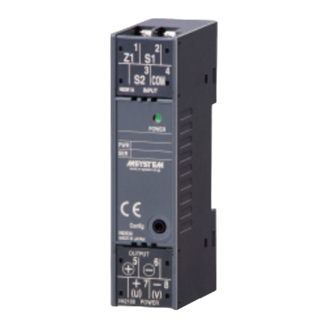
M-system M5PA User manual

M-system

M-system M5PA User manual

M-system 10TG User manual

M-system

M-system 10TG User manual

M-system W5RS User manual

M-system

M-system W5RS User manual

M-system M5YV User manual

M-system

M-system M5YV User manual

M-system M3LPA2 User manual

M-system

M-system M3LPA2 User manual

M-system W2XR User manual

M-system

M-system W2XR User manual

M-system Mini-MW Series User manual

M-system

M-system Mini-MW Series User manual

M-system M3LLC User manual

M-system

M-system M3LLC User manual

M-system 10VF User manual

M-system

M-system 10VF User manual

M-system M3LR User manual

M-system

M-system M3LR User manual

M-system 10VS User manual

M-system

M-system 10VS User manual

M-system M3LU2 User manual

M-system

M-system M3LU2 User manual

M-system 6BPA User manual

M-system

M-system 6BPA User manual

M-system Mini-M M2RS User manual

M-system

M-system Mini-M M2RS User manual

M-system 10AC User manual

M-system

M-system 10AC User manual

M-system B3FR User manual

M-system

M-system B3FR User manual

M-system Mini-M M2PA User manual

M-system

M-system Mini-M M2PA User manual

M-system Mini-M M2TT User manual

M-system

M-system Mini-M M2TT User manual

M-system M80YS User manual

M-system

M-system M80YS User manual

M-system M5XTR User manual

M-system

M-system M5XTR User manual

M-system M2EXS User manual

M-system

M-system M2EXS User manual

M-system M1EXS-2 User manual

M-system

M-system M1EXS-2 User manual

M-system F2RS User manual

M-system

M-system F2RS User manual

M-system W5 Series User manual

M-system

M-system W5 Series User manual

Popular Transmitter manuals by other brands

PR electronics 6331 Series manual

PR electronics

PR electronics 6331 Series manual

LRS TX-9561EZ user manual

LRS

LRS TX-9561EZ user manual

trafag 8252 instructions

trafag

trafag 8252 instructions

Metal Samples MS2700E Operator's manual

Metal Samples

Metal Samples MS2700E Operator's manual

E+E Elektronik EE310 Operation manual

E+E Elektronik

E+E Elektronik EE310 Operation manual

AFRISO DMU 30 operating manual

AFRISO

AFRISO DMU 30 operating manual

Mod-tronic Cecomp F16DR manual

Mod-tronic

Mod-tronic Cecomp F16DR manual

Nautel VS1 installation manual

Nautel

Nautel VS1 installation manual

Zaxcom TRXLA3 user manual

Zaxcom

Zaxcom TRXLA3 user manual

Skytech 1322WT Operating and installation instructions

Skytech

Skytech 1322WT Operating and installation instructions

Ramsey Electronics FM100B instruction manual

Ramsey Electronics

Ramsey Electronics FM100B instruction manual

Listen lt-800 user manual

Listen

Listen lt-800 user manual

Campbell WXT520 instruction manual

Campbell

Campbell WXT520 instruction manual

Bioness StimRouter User's Reference Card

Bioness

Bioness StimRouter User's Reference Card

Emerson Rosemount 3051S Series quick start guide

Emerson

Emerson Rosemount 3051S Series quick start guide

Maxital TXFO-IFTV user manual

Maxital

Maxital TXFO-IFTV user manual

Avtek Share quick guide

Avtek

Avtek Share quick guide

Spectrum SCT1500 Service manual

Spectrum

Spectrum SCT1500 Service manual

manuals.online logo
manuals.online logoBrands
  • About & Mission
  • Contact us
  • Privacy Policy
  • Terms and Conditions

Copyright 2025 Manuals.Online. All Rights Reserved.