manuals.online logo
Brands
  1. Home
  2. •
  3. Brands
  4. •
  5. Magnescale
  6. •
  7. Measuring Instrument
  8. •
  9. Magnescale LY72 Manual

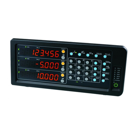
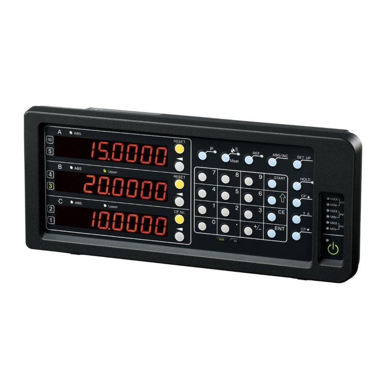
Magnescale LY72 Manual

LY72 Initial Setup Manual 1/14
LY72
Confirmation: software version 1.15
LY72
Initial Setup Manual
Initial Setup Flow
Basic
Settings
Advanced
Settings
STEP 1~3 STEP 4~5
START Finished
Advance
Preparation
Check the conditions of use
Ver.2 (2020.11) CS&S
Contents Page
Preparations before making the initial settings (checking conditions of use) 2 to 4
How to set up Basic Settings 5 to 7
How to set up Advanced Settings (continued from Basic Settings) 8 to 10
Factory Default (All Clear) 11
Appendix 1: Front panel, Alarm indication 12
Appendix 2: Adapter connections (scales and gauges) 13 to 14
Table of contents
STEP 4~5
STEP 1~3
LY72 Initial Setup Manual 2/14
Preparations before making the initial setting (1/3)
By confirming the conditions of use in advance, the setting operation can be performed easily.
Let's start with the basic settings.
Items Indication Description Setting
Axis label Select the axis label to be used for the counter display
and RS232C command. The functions that can be
used differ depending on the selected axis label.
ABC display: Function for gauge type measuring unit
XYZ display: Functions for scale type measuring unit
Axis label:
ABC or XYZ
Master calibration When the power is turned on, the system automatically
waits for the reference point detection and
automatically reproduces the reference position of the
master block.
It is necessary to adjust the reference position of the
master block once before the power is turned on.
OFF: Useless
ON: Effective:
Input axis Select how to display the number of scale axes to be
connected. When you select "Additive Display", select
the polarity (+/-) of each axis as well.
1: Single axis only
1 2: 2-axes independent
display
1 2 3: 3-axes independent
display
Destination country Please select the region to be used. STD: General Area
US: U.S.A.
JPN: Japan
Measuring unit
resolution
Set the resolution output from the measurement unit to
be used for each axis. The resolutions that can be
selected are length and angle. Expanded selections
increase the number of options.
*Angular resolution (1sec to 1 degree) when using a
rotary scale
Length: 0.05 to 100μm
*See Tables 1,2 and 3
or
Angle: 1 second to 1 degree
default
Pay attention to the functions that can be used depending on the selection of the axis label.
*The following functions cannot be selected when the XYZ label is selected.
・Master calibration function
・Peak value (maximum, minimum, P-P value) calculation function
・Timer output via RS-232C communication
Basic Setting Items
Note: Invalid when
XYZ label is selected
Measuring Unit Output
resolution
connection
cable Adapter *
SR-1711
SR-1711R
0.5μm HK-**C
HK-**CR
SZ05-T01
SR801/ MSS-101
SR801R
0.5μm HK-1**C
HK-2**C
SZ05-T01
SR801/ MSS-101
SR801R
0.5μm CE07-**C SZ51-MS01
+ SZ70-1
SR10 / SR30 /
SR50
SR50-R
0.5μm HK-4**C
HK6-**CR
SZ05-T01
SR118 0.5μm CE05-**C
CH02-**
DZ51
+ SZ70-1
SR108
SR107
0.5μm SZ51-MS01
+ SZ70-1
SR128 0.5μm CH01-**C SZ70-1
SR128 / SR127 0.5μm CH01-LW**C SZ51-MS01
+ SZ70-1
SR138R(GB-ER) 0.5μm CH04-03C
Table1: Length scale output resolution
* For adapter information, refer to Appendix 2 Adapter Connection in this Manual
Measuring Unit Output
resolution
Adapter/
conversion cable Adapter *
SL110
SL130
10μm PL20B SZ70-1
SL110
SL130
10μm PL20C
SJ300 1μm CH33-**CPD/CED
SJ700 5μm SZ70-1
SJ700A 5μm
Table 2: Digiruler output resolution
Measuring Unit Output
resolution
Adapter/
conversion cable Adapter *
DG 0.5μm SZ05-T01
DG-B 0.5μm DZ-51 SZ70-1
DL310B/330B 10μm DZ-51 SZ70-1
DK series 0.1μm or
0.5μm
CE29-**
Table3: Digital gage output resolution
LY72 Initial Setup Manual 3/14
Check the usage conditions for Advanced Settings.
Advanced Setting Items
Items Indication Description Setting
Display at Power-ON Select the display when the power is turned on
If you select "LY", "LY" will be displayed and recognized when
the power is cut off.
COUnT: count display
LY: “LY”display
Display resolution and
polarity
Set the resolution of each display axis
You cannot set a value smaller than the input resolution. Also
select the polarity (+/-).
* The initial value is the value set in the basic settings.
Length: 0.05 to 100μm
or
Angle: 1 second to 1 degree
Display contents of
each axis
Set the display contents when the power of each display axis
is turned on
Set axis input axis number and display data
* At the time of shipment, the current values are displayed for
all three axes.
* When the XYZ label is selected, display selection other than
the current value is not possible.
Input axis number:
1, 2, 3
Display data:
Present value
Maximum value
Minimum value
P-P value
Do not show
Scaling Displayed by multiplying the measured value by a
magnification
0.1 times to about 10 times
Linear compensation Set a linear compensation value for the length per 1 m ±600μm/m
*Expanded selections ±1000μm/m
Hole function Function selection during hold operation (operation key,
external input)
LATCH: Latch function
PAUSE: Pause function
General-purpose
input
Function selection of general-purpose input (1 circuit each) for
3 display axes
- Hold: Holds the display (holds on the first input and cancels
on the second input) Furthermore, holds the update of the
peak calculation when the ABC label and pause function are
selected.
- Restart: Recalculate the maximum / minimum value
- Display switching: Switching between the current value and
the selected display (maximum value, minimum value, peak
value)
- Origin load: Reproduction of reference position
- Recall: Recall preset values
Hold
Restart.(When ABC label is
selected)
Display switching(When ABC label is
selected)
Reference point Load
Recall (preset value)
General-purpose
output
Function selection of general-purpose output (1 circuit each)
for 3 display axes
- Alarm: Output when Error is displayed
- Display mode: Current value or peak value
- Origin passing signal: Output when the origin is passed
during origin operation
- Origin alarm: Output when the origin signal is not connected
and the origin speed is exceeded.
Alarm
Display mode
(When ABC label is selected)
Reference point passage signal
Reference point alarm
Key lock Function to prevent erroneous operation of Key operation
After setting, only a specific key can be used. A password
(1793) is required to unlock it.
OFF: No key lock
ON: Key lock
Current value store Select whether to display the previous value when the power
is turned on
* If you use the master alignment function in the basic settings,
it will not work even if it is turned on.
OFF: Don't save the current value
ON: Save the current value
Flicker control Prevents flickering of the smallest digit to be displayed
Set the stage to suppress flicker.
OFF: Function stop
1: Weak
2: Strong
Sleep The display turns off when there is no movement of the length
measurement unit or key operation for a certain period of time
while the power is on.
It will return when the length measurement unit is moved or
the Key operation is performed again.
OFF: Do not put to sleep
1: 1 minute later
5: 5 minutes later
10:10 minutes later
30:30 minutes later
60:60 minutes later
default
default
default
Note: Invalid when
XYZ label is selected
Preparations before making the initial setting (2/3)
Upper axis
Middle axis
Lower axis
Upper axis
Middle axis
Lower axis
Upper axis
Middle axis
Lower axis
LY72 Initial Setup Manual 4/14
Check the advanced settings for RS232C communication.
Items Indication Description Setting
RS232C
Output data mode
Set the output data mode when
receiving the data request command
(“R”).
Outputs data for 3 axes in computer
mode, and outputs data for 1 axis in
print mode.
- COMP: Computer mode
ABC axis output or XYZ axis output
- Print : Print mode
Output only A axis (when ABC label is selected)
or
Output only X axis (when XYZ label is selected)
RS232C
Output data format
Select the output data format.
・All lines output in one line
・Line feed and output
・Add a header
The selectable items differ
depending on the axis label (ABC or
XYZ)
When ABC label is selected:
AbC : Outputs one line for all axes without header
A.b.C. : New line output for each axis without header
h1AbC : Header 1 outputs one line for all axes
h1A.b.C: Header 1 outputs line feed for each axis
When XYZ label is selected:
XYZ : Output with 1 line for all axes without header
X.Y.Z. : New line output for each axis without header
h1XYZ : Header 1 outputs 1 line for all axes
h1X.Y.Z.: New line output for each axis with header 1
h2XYZ : Header 2 outputs one line for all axes
h2X.Y.Z.: Line feed output for each axis with header 2
RS232C
Output data selection
Set the output data when receiving
the data request command (“R”).
·Present value
·Maximum value
·minimum value
·P-P value
When ABC label is selected:
Cr : Current value
MAX: Maximum value
MIN : Minimum value
P-P : P-P value
*Cannot be set when XYZ axes are selected.
RS232C timer The data specified by the "R"
command can be output at fixed
intervals.
Setting range:
None
0.2, 0.5, 1, 5, 10, 30, 60, 300 (sec.)
*Cannot be set when XYZ axes are selected.
RS232C transfer rate Set the transfer rate of RS232C Setting range:
1200, 2400, 4800, 9600, 19200, 36400 (bps)
RS232C parity Set RS232C parity Setting:
none
Odd number
Even number
RS232C Stop bit Set the stop bit of RS232C Setting:
1bit
2bit
RS232C data length Set the data length of RS232C Setting:
8bit
7bit
Invalid when print mode
is selected
When ABC is
selected
When XYZ is
selected
Preparations before making the initial setting (3/3)
Advanced Setting Items
default
Invalid when XYZ label
is selected
Invalid when XYZ label
is selected
default
default
default
LY72 Initial Setup Manual 5/14
When the power is turned on for the first
time after shipment from the factory
Connect the AC adapter and turn the primary power "on".
"Axis label selection" setting display
Pressing key changes the basic setting mode in the order
in which it is set.
Step 1
When you want to change the basic
settings
The following display appears
Note: If you change the basic settings,
Detailed Settings will be reset to
the factory defaults.
Standby key light
Item feed Key
SET-UP key
Connecting the AC Adapter
AC primary power source
Enter key
Axis selection Key
Ten keys
Configure the basic settings.
Choose one of the following methods of operation.
Continued on next page
LABEL:
Select the axis label according to the intended use.
(ABC or XYZ) (Note)
Note: Selection of axis label
ABC display: Function for digital gauge type measuring unit
XYZ display: Function for length scale type measuring unit
The functions that can be used vary depending on the axis label selection.
Cannot be set when XYZ label is selected
How to set up Basic Settings (1/3)
Symbol Destination Unit
STD General area
US U.S.A.
JPNJapan
COUNTRY (Destination)
MASTER (Master
calibration function):
Select whether to start with
the master block or other
dimensions every time the
power is turned on.
COUNTRY (destination
country):
Please select your region
Signal resolution
(measuring unit resolution):
Sets the output resolution of
the scale to be connected.
Supports the input of length
and angle display units.
SIG IN (input axis):
Sets the display for the
first and second axes.
(Independent display,
axis-added display, etc.)
MASTER
Master calibration
COUNTRY
(Destination)
SIG RES
(Measuring unit resolution)
SIG IN
(Input axis)
Axis LABEL
AC adapter is energized.
Turn on key, the LED light changes from
“blinking” to “off” and then press
and hold key for 3 seconds.
After about 2 seconds
LY72 Initial Setup Manual 6/14
Enter the settings confirmed in "Preparations before making initial settings (1/3)".
Repeat steps (1), (2), and (3) to make the basic settings.
MASTER
Master calibration
COUNTRY
(Destination)
SIG RES
(Measuring unit resolution)
Do not use the
master calibration
Use the master
calibration
STANDARD
(General area)
U.S.A.
JAPAN
0.5μm
0.1μm
10μm
5μm
1μm
10 minutes
1 minute
10 seconds
1 second
Basic Settings
Step 2
SIG IN
(Input axis)
How to view
extended settings:
For extended settings,
press SART-key
when the input
resolution of each axis
is displayed.
2μm
100μm
50μm
25μm
20μm
0.05μm
1 degree
Axis LABEL
Switch with key
key to confirm the axis label
ABC or XYZ
default
default
default
default
default
Use the 1st to 3rd axes
Use the 1st axis only
Use the 1st and 2nd axes
Cannot be set when XYZ
label is selected
How to set up Basic Settings (2/3)
(1) Use key to change the basic setting item.
(2) The setting selection can be switched with key on the right side of the counter display.
(3) To define the new value, press key.
Operation:
- The current setting is displayed after about
one second. If there is no change in the setting,
the next item is displayed with key.
- The ABS lamp blinks while the parameter is
selected with the axis selection key..
LY72 Initial Setup Manual 7/14
How to Exit Basic Setting Mode
①Press key or key.
②The display changes to (CANCEL).
③Pressing ( key displays (FINISH).
④Press key.
If this is the first time you have made basic settings after shipping, the display will be
After the second time, the screen is displayed when the power is turned on.
⑤Press key. The display returns to normal.
This completes the basic settings.
Step 3
Setup key
Enter key
Select axis key
Reset key
Key to be used at the end of the basic setting mode (LY72)
Once you have completed the basic settings, exit this mode and move to
the advanced setting mode.
Φ lamp
Axis label lamp
ABS lamp
How to set up Basic Settings (3/3)
Start key
LY72 Initial Setup Manual 8/14
Press keys for each axis to
set the display resolution for each
axis.
After setting, use key to set
the resolution for each axis.
How to set up Advanced Settings (1/3) (continued from Basic Settings)
Make the advanced settings.
Display resolution
INPUT CHANGE
(Input/display switching)
Basic Settings
Angle display
Length display
Step 4
Press the setup key
in the normal count
display state.
Note 1: Selection of a value smaller than the input resolution of the basic
setting is not displayed.
Note 2: To display the diameter, turn on the Φ lamp.
Note 3: The angle display can be selected when the angular resolution
is selected in the basic settings.
Power On Display
(Display at power-on)
The display at power-on can be set.
“LY“display
Counting Display
SCALING
(scaling function)
≤ ≤
magnification
Enter scaling factor
1x
Liner Error
(Linear compensation)
~
Enter a correction value of ±0.600mm per 1m of distance
Input up to ±1.0000 mm with expansion selection.
Extended
selection by
Change polarity with key
Current value of input axis
Maximum value of input axis
Minimum value of input axis
Turn off the display
~
Extended selection
Normal
Upper axis
Middle axis
Lower axis
Input axis Display data
Enter numerical values on a numeric keypad.
Advanced Settings
default
default
default
default
P-P value of input axis
Input axis: 1, 2, 3
Display data
Φ lamp (Note 4)
*If you have already completed the basic settings and want to
reconfigure only the advanced settings, you can do the same.
Selection of display format when power is turned on for each display axis (A / B / C)
1. Press key to set to select the axis,
then select the input axis, and when confirmed, press key to set.
2. Continue to press key to select the display data,
and when confirmed, set with key
* You need to restart the main unit for the settings to take effect.
* When the XYZ axes are selected, only the current location can be set.
Diameter display (Note 2)
(Note 1)
(Note 3)
* If you select the count display, you cannot make basic settings.
Operation:
- The current setting is displayed after about
one second. If there is no change in the setting,
the next item is displayed with key.
- The ABS lamp blinks while the parameter is
selected with the axis selection key..
LY72 Initial Setup Manual 9/14
KEY LOCK
STORE
Current Value
Saving Function
FLICKER
Flicker control
function
SLEEP
sleep mode
Inhibition Weak Inhibition Strongoff
OUTPUT
General-purpose output
1 min.
none
10 min. 1h
5 min. 30 min.
setoff
set
off
HOLD Function
Hold function selection
LATCH: The display data is fixed without interrupting the internal calculation.
PAUSE: Holds peak calculation (temporarily suspends calculation of maximum
and minimum values)
Latch Pause
Display data switching
Ref. input load
Key lock function can be set (to prevent accidental operation)
It is possible to save the display at power-off and display the value at power-on.
Flickering of the smallest digits can be suppressed in two stages
If no operation or scale movement is performed for a certain period of time,
the display will turn off.
How to set up Advanced Settings (2/3)
Advanced Settings
default
default
default
default
default
HOLD Restart
Alarm Display mode
Reference point passing signal
Function selection of general-purpose output (1 circuit each) for 3 display axes
* Some items may not appear when the axis label XYZ is selected.
key to change
key to decide the selection
Recall(preset value)
Reference point Alarm
Cannot be set when XYZ label is selected
default
Invalid when XYZ
label is selected
INPUT
General-purpose input
Function selection of general-purpose input (1 circuit each) for 3 display axes
* Some items may not appear when the axis label XYZ is selected.
key for the axis to change
key to decide the selection
Upper axis
Middle axis
Lower axis
Upper axis
Middle axis
Lower axis
default
default
default
LY72 Initial Setup Manual 10/14
RS232C function setting
6.When the advanced settings are complete, switch to the normal display.
Press key.
This completes the initial settings.
Print mode
Computer mode
RS232C output data mode selection
Select the output data format when selecting the computer mode
Select with key to add or not add header
Select whether or not to insert line breaks for each axis with the key
Invalid when print
mode is selected
When ABC label is selected When XYZ label is selected
Select default settings for output data
(Output data can be changed by RS232C command)
current value maximum value minimum value peak to peak value
Set automatic data output at fixed time intervals (unit: ms)
Select the transfer rate of RS232C (unit: bps)
Select RS232C parity check
None Odd Even
Select stop bit of RS232C
1 stop bit 2 stop bit
Select RS232C data length
8 bit 7 bit
Step 5
How to set up Advanced Settings (3/3)
Advanced Settings
MODE
Output Data mode
FORM
Data output format
r DATA
Output data selection
TIMER
bPS
transfer speed
Parity
STOP
Stop bit
LENGTH
Data length
Invalid when XYZ
label is selected
Invalid when XYZ
label is selected
default
default default
default
default
default
default
default
default
LY72 Initial Setup Manual 11/14
2. When you press key, (slf_tst) is displayed,
followed by (Tst Sel)
3. Pressing key changes the display as shown below.
4. Turn off the primary power supply to the AC adapter.
1. Hold down key and key at the same time to start the power supply.
⇒The model name of the counter is displayed
Factory setting (All clear)
Reference key
Connect the AC adapter to the DC-IN input
on the back of the counter and turn on the
primary power supply.
Setup key
Connecting the AC Adapter
primary power source
DC-IN
Mainly used keys
How to check the software version:
Power ON → Display LY → Key → Version
Press any key to return to the LY display.
To set the factory settings (all clear), perform the following operations.
Make preparation such as taking notes in advance for necessary items.
Also, do not perform any operation other than the explanation.
START
completion
→ → →
→ → →
Caution: If you do this, all settings will be the factory default settings.
LY72 Initial Setup Manual 12/14
Appendix 1
Alarm indication
Display Status Display Status
Measurement unit not
connected Storage data error
Speed over (Note)Reference point detection
error
Overflow
Power failure
Note: When using an adapter connection (SZ**), no speed override indication is shown, but rather an error message.
(Light)
(Blinking)
Front panel
No. Name No. Name No. Name
①Axis label ⑦P key ⑬PRINT key
②ABS lamp ⑧Datum point value/Master
combination value setting key ⑭Standby key
③Φ lamp ⑨REF key ⑮Numeric key
④Counter display ⑩ABS/INC key ⑯Function key
⑤RESET key ⑪SETUP key ⑰Peak value lamp
⑥Axis select key ⑫HOLD key
LY72 Initial Setup Manual 13/14
Appendix 2-1 Adapter connection (Length scale)
SZ51-MS01/SZ51-DR01
* HA13A, 15A, 23A and 25A are used as head amps
Screws
Screws
Screws
Head-amp
Connector
SZ05-T01
Connector
Screws
Cable (300mm)
SZ70-1
Counter unit
Head-amp
connector
Screws
Cable (300mm)
Counter unit
Screws
Use screws to secure it in place.
SZ70-1
Use screws to secure it in place.
Scale/ Head Resolution Adapter Counter
SR128(GB-A) 0.5μm SZ70-1 LG20
LH70/71/71A/72
LY71/72
PL20B 10μm
SJ700 5μm
Scale/ Head Resolution Adapter 1 Adapter 2 Counter
SR108(GB) 0.5μm SZ51-MS01 SZ70-1 LG20
LH70/71/71A/72
LY71/72
PL20A 10μm SZ51-DR01
Scale Resolution Adapter Counter
SR-1711(GP)、SR10A/741(GS)、
SR50A(GF,GF-R)、SR30A(GM)、
SR801/801R(GL)
0.5μm SZ05-T01 LG20
LH70/71/71A/72
LY71/72
LY72 Initial Setup Manual 14/14
DZ51
Adapter connection (Digital gauge)
Screws
Screws
Screw
Appendix 2-2
Head-amp
Connector
Connector
Screws
SZ05-T01
connector
Cable (300mm)
SZ70-1
Counter unit
Head-amp
Screws
Cable (300mm) Counter unit
Use screws to secure it in place.
SZ70-1
Counter unit
Screws
DK series CE29-**
Use screws to secure it in place.
Gauge Resolution Adapter 1 Adapter 2 Counter
DG-B 0.5μm DZ51 SZ70-1 LG20
LH70/71/71A/72
LY71/72
DL310B/330B 10μm
Gauge Resolution Adapter Counter
DG 0.5μm SZ05-T01 LG20
LH70/71/71A/72
LY71/72
Gauge Resolution Adapter Counter
DE12BR/30BR 0.1μm SZ70-1 LG20
LH70/71/71A/72
LY71/72
Gauge Resolution Connection cable Counter
DK-** 0.1um
or
0.5μm
CE29-**
**: 003/01/03/05/10
(0.3 to 10m)
LG20
LH70/71/71A/72
LY71/72

Other manuals for LY72

1

Other Magnescale Measuring Instrument manuals

Magnescale DK830SR User manual

Magnescale

Magnescale DK830SR User manual

Magnescale SR77 Owner's manual

Magnescale

Magnescale SR77 Owner's manual

Magnescale LH71 Series Manual

Magnescale

Magnescale LH71 Series Manual

Magnescale DK Series User manual

Magnescale

Magnescale DK Series User manual

Magnescale DZ174-010 User manual

Magnescale

Magnescale DZ174-010 User manual

Magnescale SR75 Owner's manual

Magnescale

Magnescale SR75 Owner's manual

Magnescale DK812 Series User manual

Magnescale

Magnescale DK812 Series User manual

Magnescale DG205 Series User manual

Magnescale

Magnescale DG205 Series User manual

Magnescale DK812 Series User manual

Magnescale

Magnescale DK812 Series User manual

Magnescale MJ632 User manual

Magnescale

Magnescale MJ632 User manual

Magnescale MG10A-P1 User manual

Magnescale

Magnescale MG10A-P1 User manual

Magnescale DS10NR5 User manual

Magnescale

Magnescale DS10NR5 User manual

Magnescale LY71 User manual

Magnescale

Magnescale LY71 User manual

Magnescale DZ176 User manual

Magnescale

Magnescale DZ176 User manual

Magnescale LH70 User manual

Magnescale

Magnescale LH70 User manual

Magnescale U12B User manual

Magnescale

Magnescale U12B User manual

Magnescale DK812A Series User manual

Magnescale

Magnescale DK812A Series User manual

Magnescale SR85 Owner's manual

Magnescale

Magnescale SR85 Owner's manual

Magnescale DF805SR User manual

Magnescale

Magnescale DF805SR User manual

Magnescale MT Series User manual

Magnescale

Magnescale MT Series User manual

Magnescale SR87 Owner's manual

Magnescale

Magnescale SR87 Owner's manual

Magnescale LY71 User manual

Magnescale

Magnescale LY71 User manual

Magnescale DF830SLR User manual

Magnescale

Magnescale DF830SLR User manual

Magnescale LY71 Service manual

Magnescale

Magnescale LY71 Service manual

Popular Measuring Instrument manuals by other brands

A.W. Sperry Instruments DSA-500 operating instructions

A.W. Sperry Instruments

A.W. Sperry Instruments DSA-500 operating instructions

Measurement Computing USB-5203 user guide

Measurement Computing

Measurement Computing USB-5203 user guide

Siemens Milltronics C-40 instruction manual

Siemens

Siemens Milltronics C-40 instruction manual

VERIS INDUSTRIES, INC. E31E Series installation guide

VERIS INDUSTRIES, INC.

VERIS INDUSTRIES, INC. E31E Series installation guide

sauter CP P1 instruction manual

sauter

sauter CP P1 instruction manual

Tower Hobbies Expanded Scale Voltmeter instructions

Tower Hobbies

Tower Hobbies Expanded Scale Voltmeter instructions

Klein Tools ET180 instruction manual

Klein Tools

Klein Tools ET180 instruction manual

Labom GA261 Series operating instructions

Labom

Labom GA261 Series operating instructions

Endress+Hauser Micropilot FMR53 technical information

Endress+Hauser

Endress+Hauser Micropilot FMR53 technical information

NI 5114 Getting started guide

NI

NI 5114 Getting started guide

Toshiba LF232*F Series instruction manual

Toshiba

Toshiba LF232*F Series instruction manual

Calex C1 manual

Calex

Calex C1 manual

GHM GREISINGER GMK 100 operating manual

GHM

GHM GREISINGER GMK 100 operating manual

Omega FTB-1000 Series Operator's manual

Omega

Omega FTB-1000 Series Operator's manual

CBS C-RD-SONDE operating manual

CBS

CBS C-RD-SONDE operating manual

Tektronix WVR8200 user manual

Tektronix

Tektronix WVR8200 user manual

Brymen BM857s user manual

Brymen

Brymen BM857s user manual

YOKOGAWA SC21 Series instruction manual

YOKOGAWA

YOKOGAWA SC21 Series instruction manual

manuals.online logo
manuals.online logoBrands
  • About & Mission
  • Contact us
  • Privacy Policy
  • Terms and Conditions

Copyright 2025 Manuals.Online. All Rights Reserved.