manuals.online logo
Brands
  1. Home
  2. •
  3. Brands
  4. •
  5. Magnescale
  6. •
  7. Measuring Instrument
  8. •
  9. Magnescale LH70 User manual

Magnescale LH70 User manual

1/5
LH70 Tool offset function Operating manual
Contents Page
1. First of all 1
2. Target model 2
3. Front panel 2
4. Positional relationship between TOOL master (reference) and other TOOLs (conceptual diagram) 2
5. Settings
and operations
Change tool master number 3
Tool master coordinate setting (for scale with reference point) 3
Tool master coordinate setting (for scale with reference point) 4
Setting the number and offset value of the tool to be used 5
Ver. 3 (2021.1)
CS&S
LH70
Tool offset function
Operation manual
1. First of all
OPERATION FLOW
The tool offset function is used in absolute mode (ABS). You must set up a tool master to use this function. The
coordinate position of each tool is a coordinate value managed by the offset amount with respect to the tool master.
Therefore, if you change the value of the tool master, the coordinates of other tools will change automatically.
The tool master is set to number 1 in the factory settings, but in this operation manual, the tool master is set to a tool
number that is not normally used. Then, in the actual operation, we will explain how to set and operate only the tools
that are normally used without using the tool master.
NOTE: Set the X-axis display setting to diameter display (Φ lamp lights up).
Change tool
master number
Tool master
coordinate settings
Setting the number
and offset value
START Finished
STEP 1 STEP 2 STEP 3
Table of contents
STEP 1
STEP 2-1
STEP 3
STEP 2-2
LH70
2/5
LH70 Tool offset function Operating manual
2. Target model
Item Model name Remarks
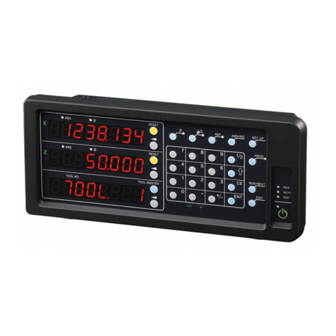
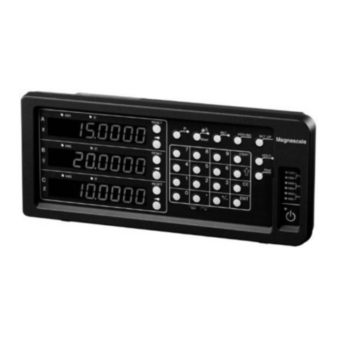
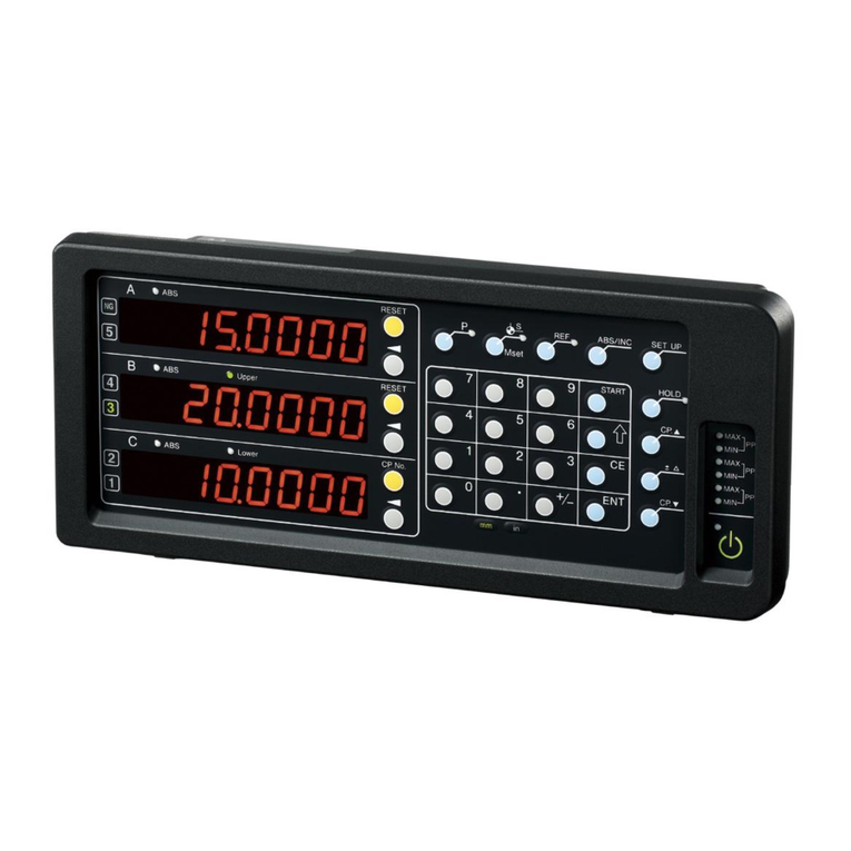
Display unit LH70-3(3 axes input)For Lathe
・Tool offset: Up to 12 points
Measuring unit GB-ER Built-in reference point
SJ700A No reference point
SL110, SL130, PL20C No reference point
* The tool master is set to No. 1 at the
time of shipment from the factory.
LH70-3
3. Front panel
4. Positional relationship between TOOL master (reference)
and other TOOLs (conceptual diagram)
X
Z
チャック
P0 = (X0, Z0)
P1 = (X0+X1, Z0+Z1)
P2 = (X0+X2, Z0+Z2)
Position coordinates of each tool
Datum point
TOOL 1 TOOL 2
Z2
X2
Z1
X1
P0 (X0,Z0)
P2
P1 Datum point
Chuck
ABS lamp
Datum point setting / tool offset key
Select axis key Item feed key
Enter key Edit key
Select key
ABS/INC key
TOOL #
(Tool master)
# : 12
Workpiece
3/5
LH70 Tool offset function Operating manual
Press the Z-axis key and press key in that order. The display shows the value when the reference point is loaded.
If the display value is not , press key and then use the numeric
and keys to change the display to 0.0000.
Press the X-axis key, then key, and key.
The display shows the value when the reference point is loaded.
If the displayed value is not , press key.
Then press the numeric key (0.0)
and change the display to 0.0000 with key.
Move the measuring unit to pass the reference point.
When the reference point is detected, counting starts, and the X-axis reference point loading is completed.
Press key (Reference). ( lamp lights up)
At this time, the tool number display in the lower row automatically switches to
the tool master number.
Press the tool offset key to enter tool offset mode.
Press key. ( lamp lighting)
Change tool master number:
The tool master is set to number 1 when shipped from the factory, but change this to a number that is not
normally used. Since a general lathe uses about 8 tools at a time, change the tool master to 12.
1 2 3 4 5
6 7 8 9 10
11 12
Tool offset for LH70-3 : up to 12 points
In the case of LH70
The number with the period “.” here is the tool
master (reference coordinates).
Turn on the power of the display unit, you do not have to attach the tool.
Press key on the lower TOOL display, enter the number (12) with the numeric keypad,
and press key.
Then press key
Select the tool master as # 12
Tool master coordinate setting (for scale with reference point):
If you are using a measuring unit with a reference point, load the reference point once and set the reference
point position to the reference value (X, Z = 0,0). By performing this operation, the tool coordinates can be
reproduced by detecting the reference point position at the start of work.
When using the 2-axis addition function on the Z-axis, do not load the origin, but move the tool post to the center
of the machine movable range to set the Z-axis reference value. (See step 2-2)
* For a measuring unit without reference point function, proceed to step 2-2.
1. With the tool master as # 12, load the reference point on the X and Z axes and set the reference point position to be the datum point.
X axis
Reference point
Z axis
Reference point P0 (X0,Z0)
Datum point
5. Settings and operations
P0 is in absolute mode
(X=0.0000 Z=0.0000)
(Continued on the next page)
STEP 1
STEP 2-1
2. Perform the same operation for the Z axis so that the reference point position is the datum point (0.000).
Lower row
4/5
LH70 Tool offset function Operating manual
Make sure lamp is lit.
If the lamp is not lit, press key to enter tool offset mode.
Set the tool number to #1.
Operate the key, numeric key, and key on the lower display to enter "1".
Tool master coordinate setting (for scale with reference point):
Set any position within the effective scale length range as the datum point (X, Z = 0,0). This operation
method describes the operation to set the center of the machine movable range as the datum point.
1. The tool master is # 12 and moves the cutting tool holder so that it is approximately in the center of the range of motion on the
X and Z axes.
Move the tool post to the center of
the movable range of the X-axis and
Z-axis
Enter the reference value directly on the X-axis and Z-axis.
Press the X-axis key, enter the numerical value 0.0, and press key.
2. Set the Z-axis datum value .
Press the Z-axis key and enter the number(0.0). And press key
The X-axis datum point value is now saved in memory in the tool master # 12.
Set the Z-axis datum value to zero (0)
Zaxis
Set the X-axis datum value to zero (0)
X axis
This completes the setting of the X-axis and Z-axis datum point for the tool master #12.
Z1
Z2
X
Setting the number and offset value of the tool to be used:
Set the cutting tool to be actually used on the cutting tool holder, perform machining, measure the
dimensions of the workpiece, and enter the value.
Up to step 2, you have performed the operations related to the tool master settings. In step 3, set the tool to be actually used.
The procedure is as follows.
①Set the number of the tool (byte) to be used
②Machine the workpiece with the tool and enter its dimensions on the X and Z axes
When setting another tool, set the tool number in the same way (switch tool number), execute machining, measure the workpiece,
and set its value.
Fig.1
Φ50.0
Workpiece Φ50 round bar (before processing)
TOOL1
(Lower)
1. Attach the bite to the tool post. (Fig.1).
Enter the tool number of this byte (here, number 1) to switch the display.
X
Z
Move the measuring unit to pass the reference point.
This completes the setting of the X-axis and Z-axis datum point for the tool master #12.
NOTE: When the 2-axis addition function is used on the Z-axis, the reference point detection is enabled on both the Z1 and Z2 axes
on the display unit side. Therefore, if the position of either measuring unit shifts, the reference position will shift.
STEP 3
STEP 2-2
(Continued on the next page)
5/5
LH70 Tool offset function Operating manual
2. Make a reference plane on the right edge of the workpiece. Cut the right
end face with a cutting tool by an appropriate amount.(Fig. 2)
After cutting to the extent that the center is left a little, leave the Z axis as it
is without moving it.
3. This surface is used as the reference surface of the workpiece. Set the Z
axis to “0.0” without moving the Z axis.
This completes the Z-axis reference (offset value).
4. Next, set the X-axis reference (offset value).
The workpiece is cut and fed in the X-axis direction (Fig. 3).
5. The diameter of the workpiece in the cut part is measured without
moving the X axis. (Fig. 4)
Enter the measured value on the X-axis.
For example, if the diameter of the cut part is 40 mm, operate as follows.
This completes the tool offset for tool # 1.
When the turret, bite, etc. become obstacles and the diameter cannot
be measured:
You can move the axis freely by holding the displayed value. After moving
the axis to a position where it can be measured, measure the workpiece
and enter the measured value.
Example of hold operation for X-axis display
Press the X-axis key and press key.
If you want to enter a different tool offset, change the tool number and repeat steps 1-5 in step 3.
If the tip of the cutting tool is worn, the machining dimensions are misaligned, or the sharpness is getting worse, replace the
cutting edge of the cutting tool or polish the cutting edge, and then perform steps 1 to 5 in step 3 to reset the value.
Fig.2
Φ50.0
Workpiece reference surface processing (right end
surface Z axis)
TOOL1
Fig.3
Φ50.0
Workpiece reference surface processing
(diameter X-axis)
TOOL1
Reference plane
Fig.4
Φ50.0
Measurement of workpiece machining
dimensions (diameter)
TOOL1
40.0
Center
Z axis
(Middle)
X axis
(Upper)
When entering a different tool offset
When the tip of the cutting tool is worn, the offset value is deviated, or the
sharpness is getting worse
Reference plane

Other manuals for LH70

4

This manual suits for next models

1

Other Magnescale Measuring Instrument manuals

Magnescale LY71 User manual

Magnescale

Magnescale LY71 User manual

Magnescale DZ174-010 User manual

Magnescale

Magnescale DZ174-010 User manual

Magnescale DF805SR User manual

Magnescale

Magnescale DF805SR User manual

Magnescale MT Series User manual

Magnescale

Magnescale MT Series User manual

Magnescale LY71 Manual

Magnescale

Magnescale LY71 Manual

Magnescale U12B User manual

Magnescale

Magnescale U12B User manual

Magnescale DK Series User manual

Magnescale

Magnescale DK Series User manual

Magnescale DK812SAFR User manual

Magnescale

Magnescale DK812SAFR User manual

Magnescale DT12N User manual

Magnescale

Magnescale DT12N User manual

Magnescale SR75 Owner's manual

Magnescale

Magnescale SR75 Owner's manual

Magnescale DZ176 User manual

Magnescale

Magnescale DZ176 User manual

Magnescale DS50NR5 User manual

Magnescale

Magnescale DS50NR5 User manual

Magnescale DK812A Series User manual

Magnescale

Magnescale DK812A Series User manual

Magnescale DS10NR5 User manual

Magnescale

Magnescale DS10NR5 User manual

Magnescale DL310B User manual

Magnescale

Magnescale DL310B User manual

Magnescale SR75 Owner's manual

Magnescale

Magnescale SR75 Owner's manual

Magnescale DG205 Series User manual

Magnescale

Magnescale DG205 Series User manual

Magnescale SR85 Owner's manual

Magnescale

Magnescale SR85 Owner's manual

Magnescale PL101 Series User manual

Magnescale

Magnescale PL101 Series User manual

Magnescale SR87 Owner's manual

Magnescale

Magnescale SR87 Owner's manual

Magnescale LH71 Series User manual

Magnescale

Magnescale LH71 Series User manual

Magnescale LASERSCALE BL55-RU Series User manual

Magnescale

Magnescale LASERSCALE BL55-RU Series User manual

Magnescale DK812S Series User manual

Magnescale

Magnescale DK812S Series User manual

Magnescale DK812 Series User manual

Magnescale

Magnescale DK812 Series User manual

Popular Measuring Instrument manuals by other brands

Hanna Instruments HI 96759C instruction manual

Hanna Instruments

Hanna Instruments HI 96759C instruction manual

Hawk MiniWave Ultrasonic Level Series user manual

Hawk

Hawk MiniWave Ultrasonic Level Series user manual

Ursalink AM100 Series user guide

Ursalink

Ursalink AM100 Series user guide

Veris Industries Hawkeye H949 installation guide

Veris Industries

Veris Industries Hawkeye H949 installation guide

R&S SMB100A Release notes

R&S

R&S SMB100A Release notes

Openbox TSC-200 HEVC user manual

Openbox

Openbox TSC-200 HEVC user manual

GANN HYDROMETTE UNI 1 operating instructions

GANN

GANN HYDROMETTE UNI 1 operating instructions

Videoswitch VDM-9G160 user manual

Videoswitch

Videoswitch VDM-9G160 user manual

TESTO 330 instruction manual

TESTO

TESTO 330 instruction manual

Electronics TSP-M instruction manual

Electronics

Electronics TSP-M instruction manual

ELBRO LX-1148SD Operation manual

ELBRO

ELBRO LX-1148SD Operation manual

Hameg HM5012 manual

Hameg

Hameg HM5012 manual

PMK ENVI PHT 312-RO instruction manual

PMK

PMK ENVI PHT 312-RO instruction manual

Delphin Loggit Series quick start guide

Delphin

Delphin Loggit Series quick start guide

ETCR ETCR 4000A manual

ETCR

ETCR ETCR 4000A manual

Hioki SM9001 instruction manual

Hioki

Hioki SM9001 instruction manual

YOKOGAWA VY Series user manual

YOKOGAWA

YOKOGAWA VY Series user manual

Endress+Hauser Cerabar PMP21 operating instructions

Endress+Hauser

Endress+Hauser Cerabar PMP21 operating instructions

manuals.online logo
manuals.online logoBrands
  • About & Mission
  • Contact us
  • Privacy Policy
  • Terms and Conditions

Copyright 2025 Manuals.Online. All Rights Reserved.