manuals.online logo
Brands
  1. Home
  2. •
  3. Brands
  4. •
  5. Magnescale
  6. •
  7. Measuring Instrument
  8. •
  9. Magnescale DF805SR User manual

Magnescale DF805SR User manual

Instruction Manual
Digital Gauge
DF805SR / SLR / SFR / SFLR
DF812SR / SLR / SFR / SFLR
General precautions
• Before and during operations, be sure to check that our products
function properly.
• Provide adequate safety measures to prevent damages in case our
products should develop malfunctions.
• Use outside indicated specications or purposes and modication
of our products will void any warranty of the functions and
performance as specied of our products.
• When using our products in combination with other equipment,
the functions and performances as noted in this manual may
not be attained, depending on operating and environmental
conditions.
Read all the instructions in the manual carefully before use and
strictly follow them.
Keep the manual for future references.
Safety Precautions
Magnescale Co., Ltd. products are designed in full consideration of
safety. However, improper handling during operation or installation
is dangerous and may lead to re, electric shock or other accidents
resulting in serious injury or death. In addition, these actions may
also worsen machine performance.
erefore, be sure to observe the following safety precautions in
order to prevent these types of accidents, and to read these “Safety
Precautions” before operating, installing, maintaining, inspecting,
repairing or otherwise working on this unit.
Warning Indication Meanings
e following indications are used throughout this manual, and
their contents should be understood before reading the text.
Symbols requiring attention Symbols prohibiting actions
CAUTION ELECTRICAL
SHOCK DO NOT
DISASSEMBLE
Warning Failing to follow the precaution items given
below may lead to severe injury or death.
• Do not damage, modify, excessively bend, pull on, place
heavy objects on or heat the cable, as this may damage the
cable and result in re or electric shock.
• Do not disassemble or modify the unit, as this may result
in injury or electric shock. ese actions may also damage
the internal circuitry.
Caution Failing to follow the precaution items given
below may lead to injury or damage to
surrounding objects.
• e unit does not have an explosion-proof structure.
erefore, do not use the unit in an atmosphere charged
with inammable gases as this may result in re.
2013.3
Printed in Japan
©2013 Magnescale Co., Ltd.
DF805SR / SLR / SFR / SFLR
DF812SR / SLR / SFR / SFLR
2-A01-182-1A
[For U.S.A. and Canada]
THIS CLASS A DIGITAL DEVICE COMPLIES WITH PART15 OF
THE FCC RULES AND THE CANADIAN ICES-003. OPERATION
IS SUBJECT TO THE FOLLOWING TWO CONDITIONS.
(1) THIS DEVICE MAY NOT CAUSE HARMFUL INTERFERENCE,
AND
(2) THIS DEVICE MUST ACCEPT ANY INTERFERENCE
RECEIVED, INCLUDING INTERFERENCE THAT MAY CAUSE
UNDERSIGNED OPERATION.
CET APPAREIL NUMÉRIQUE DE LA CLASSE A
EST CONFORME À LA NORME NMB-003 DU CANADA.
Shinagawa Intercity Tower A-18F, 2-15-1, Konan, Minato-ku, Tokyo 108-6018, Japan
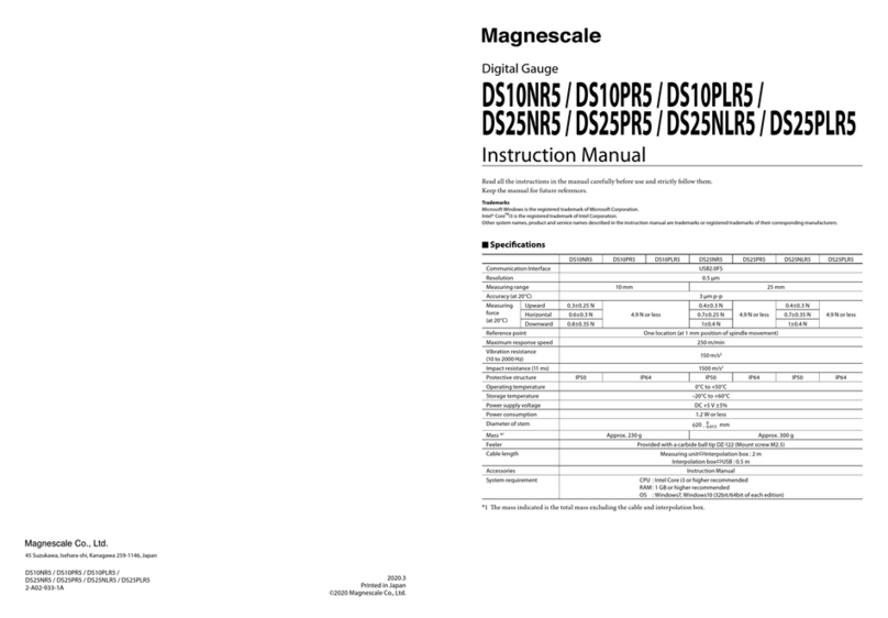
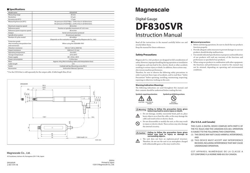
Specications
Model name DF805SR, DF805SFR DF805SLR, DF805SFLR DF812SR, DF812SFR DF812SLR, DF812SFLR
Measuring range 5 mm 12 mm
Resolution 0.1 μm
Accuracy (at 20°C) 1 μm
Measuring force (at 20°C) Upward : 0.35±0.25 N
Horizontal : 0.40±0.25 N
Downward : 0.45±0.25 N
Upward : 0.4±0.3 N
Horizontal : 0.5±0.3 N
Downward : 0.6±0.3 N
Maximum response speed 80 m/min
Reference point Position at spindle movement of 1±0.5 mm
Reference point response speed 80 m/min
Output Serial communication protocol
Spindle drive system Spring push
Number of cycles tested 60 million
(Depends on the evaluation test dened by Magnescale Co., Ltd.)
Protection grade
(Not including interpolation box and
connector)
IP66 IP54
When connecting the
φ4 mm tube: IP67
IP66 IP54
When connecting the
φ4 mm tube: IP67
Vibration resistance 100 m/s2(20 to 2000 Hz)
Impact resistance 1000 m/s2(11 ms)
Operating temperature 0 to 50°C
Storage temperature –20 to 60°C
Power supply DC +10 to +30 V
Power consumption 1.2 W or less
Mass Approx. 30 g (Not including cable and interpolation box)
Cable length 2 m
Feeler Carbide ball tip, Mounting screw M2.5
Accessories Instruction Manual, Spanner
Hose elbow (DF8**S*L*only)
Tightening nut, Clamp spanner, Wave washer, Pin (DF8**S*F** only)
*Use the CE34 that is sold separately for the output cable. (Cable length Max.20 m)
DF812SFLR
DF812SFR
φ9.5
φ7.9
φ12
109.7
5.7
24.98.1
60.6
5.8
8
M9
φ9.5
φ7.9
φ12
0
−0.009
0
−0.009
5.8
109.6
21
5.7
839.3
8.1 24.9
0.66
M9
DF812SLRDF812SR
109.7
57.233
8.1
6
3(9.2)
(t0.3)
0.6
19.5
φ80
−0.009
φ8
φ14
φ14.5
(17.5)
0
−0.009
109.6
39.3
21
19.5
24.9
8.1
6 0.6
DF805SFLRDF805SFR
82.7
24.68.75.3
8.1
21
60.6
14.2
6
8.1
0.6
14.2
5.3 8.7 4
4
82.8
φ9.5
φ9.5
φ12
φ7.9
φ7.9
φ12
0
−0.009
0
−0.009
M9 M9
DF805SLRDF805SR
21
82.7
31.61114.28.1
60.6
82.8
49.5
6
66
70
79
1815
0.6
8.1 14.2 11
φ80
−0.009
φ80
−0.009
Unit: mm
Feeler
(Stem)
(Stem)
Hose elbow
Tightening
nut
(DF8**S*F only)
Wave
washer
Interpolation box
Cable length: 2 m
(Stem)
(Stem)
Mounting Instructions
Installation environment
• Do not use the unit in places where it may receive excessive
shocks. Otherwise the inside of the unit may be damaged or the
unit may become unable to produce normal output signals.
• Locate the measuring unit at least 10 cm away from a strong
magnetic source. (e measuring unit must not be used in
magnetic elds exceeding 5 mT.)
• Do not place the measuring unit where it is exposed to splash of
water or oil.
Mounting
• Be sure to turn o the power switch of the digital tolerance
indicator before connecting or disconnecting the output cable.
• When attaching and removing the feeler, use the supplied
spanner. Be careful not to apply torque exceeding 0.1 N·m to the
spindle. is could lead to a breakdown.
To prevent the feeler from becoming loose, it is recommended
to either attach the supplied spring washer (nominal size: 2.5)
or use a screw lock. (tightening torque reference value: 0.05–
0.06 N·m)
Stem
Spindle
Supplied spanner
Spring washer
Feeler
Fig. 1
• Fix the cable in a suitable position to prevent possible cable
breakage. Never handle the cable by forcibly pulling or bending
it. (Inside bend radius 50 mm or more)
• e measuring accuracy depends on the mounting parallelism.
Adjust the squareness to the measuring surface or the parallelism
to the movement to within 0.02 mm/14 mm.
• Aer the stem is secured, do not apply force in the rotational
direction. is could cause a failure.
DF805SR / DF805SLR / DF812SR / DF812SLR
• e measuring unit comprises ball bearings. erefore, chucking
the stem of the measuring unit too tightly when mounting may
damage the spindle and prevent its smooth motion.
• Attach the stem by tightening a screw into the slot as shown
in Fig. 3. Never attach by screw threading in the φ8 mm hole
vertical direction, pressing the stem, and then tightening with a
screw. is could result in poor sliding and low precision.
• Be absolutely sure to chuck the stem part when mounting the
measuring unit.
• Using Fig. 2 as a reference, select which holder to have ready at
the mounting side.
Tightening torque: 0.6 N・m
Material: SUS303
M3 14
8.5
1
φ8G6 +0.014
+0.005
Unit: mm
9
Fig. 2 Dimensions and Dimensional Tolerance
for the Mounting Holder
DF805 : 8
DF812 : 18
DF805SFR / DF805SFLR / DF812SFR / DF812SFLR
• Be sure to use the supplied tightening nut, wave washer, clamp
spanner and pin to mount the measuring unit. (Fig. 3)
Note
e tightening torque should be roughly that needed to completely
atten the wave washer.
Recommended tightening torque: 0.6 to 1.0 N·m
Maximum tightening torque : 2.0 N·m
Pin
Measuring unit
Mounting plate
Wave washer
Tightening nut
Clamp spanner
Fig. 3
• Using Fig. 4 as a reference, select which holder to have ready at
the mounting side.
φ9.7±0.15 mm
DF805SF Series : 7 to 11 mm
DF812SF Series : 9 to 11 mm
Fig. 4
Maintenance
• Calibration is recommended every year.
• is unit is equipped with an anti-dust bellows on the
spindle. Organic solvents, ozone, ultraviolet rays, and other
adverse conditions in the ambient atmosphere can cause rapid
deterioration of the anti-dust bellows. When using in these
environments, replace anti-dust bellows periodically (every six
months to one year).
When providing an IP67 protection grade
(DF805SLR / DF805SFLR / DF812SLR / DF812SFLR)
Procedure
1. Remove the cap.
Cap Supplied spanner
Fig. 5 Removing the cap
2. Attach the hose elbow.
Tighten the M5 screw by hand until the gasket contacts the
wall, and then use the supplied spanner to tighten an additional
approx. 90°.
Supplied
spanner
Tighten in the
parallel position.
Hose elbow M5 screw
Gasket
Hose elbow
Hose elbow
Fig. 6 Attaching the hose elbow
3. Attach the φ4 mm air tube.
φ4 mm air tube
Fixing ring Fixing ring
Fig. 7 Attaching the φ4 mm air tube
Place the end of the air tube in a location where it will not come into
contact with water, oil or dust.
When driving the unit using air
(DF805SLR / DF805SFLR / DF812SLR / DF812SFLR)
Aer attaching the air tube, construct the air pressure circuit as
shown in Fig. 8.
Speed controller
Optimum vacuum rate
0.04 to 0.067 MPa
Vacuum
ejector
P
R
PV
A
Solenoid
valve
Regulator
Air lter
Pressure
source
Dry air
EXE
Fig. 8
Mist separator
Injection of air causes the spindle to perform the retraction
operation.
If the spindle ejection speed is too fast, an error may appear on the
display the moment that the workpiece is touched. Excessive impact
may dislodge the retainer inside the bearing, causing the measuring
range to be reduced. In this case, use a speed controller as shown in
Fig. 8 to adjust the spindle speed.
Troubleshooting
e operating status of the measuring unit can be checked using the LED
indicator.
LED lighting color Details Remedial action
Lights in blue. The power is turned on. Normal operation
is now performed. The reference point has
been detected.
-
Blinks in blue. The power is turned on.
The reference point standby status is
established or the reference point is being
detected.
When the reference point is used, turn on the power with the spindle
extended as far as possible, and then move the spindle 1.5 mm or more.
When the power is turned on with the spindle stopped near the reference
point position, it may not be possible to detect the reference point or the
reference point may shift.
When the reference point will not be used, set the reference point use setting
to OFF at the digital tolerance indicator.
Blinks in red. The signal level of the measuring unit is
abnormal.
After dealing with the factor suspected to be responsible for the alarm, turn
the power back on.
If the same symptoms persist even after the power has been turned back
on, the measuring unit or digital tolerance indicator might be malfunctioned.
Lights in red. The maximum response speed has been
exceeded. The signal level of the measuring
unit is abnormal. Serial communication
trouble has occurred. Normal operation
cannot be performed due to the eects
such as external noise etc.
O Power OFF If the same symptoms persist even when the power has been turned on, the
measuring unit or digital tolerance indicator might be malfunctioned.
LED indicator

This manual suits for next models

7

Other Magnescale Measuring Instrument manuals

Magnescale SR75 Owner's manual

Magnescale

Magnescale SR75 Owner's manual

Magnescale LH70 User manual

Magnescale

Magnescale LH70 User manual

Magnescale MT Series User manual

Magnescale

Magnescale MT Series User manual

Magnescale LASERSCALE BL55-RU Series User manual

Magnescale

Magnescale LASERSCALE BL55-RU Series User manual

Magnescale LH72 Manual

Magnescale

Magnescale LH72 Manual

Magnescale DT12N User manual

Magnescale

Magnescale DT12N User manual

Magnescale DF830SLR User manual

Magnescale

Magnescale DF830SLR User manual

Magnescale DS10NR5 User manual

Magnescale

Magnescale DS10NR5 User manual

Magnescale LY71 User manual

Magnescale

Magnescale LY71 User manual

Magnescale LY71 Manual

Magnescale

Magnescale LY71 Manual

Magnescale U12B User manual

Magnescale

Magnescale U12B User manual

Magnescale DS50NR5 User manual

Magnescale

Magnescale DS50NR5 User manual

Magnescale MG10A-P1 User manual

Magnescale

Magnescale MG10A-P1 User manual

Magnescale DK812SAFR User manual

Magnescale

Magnescale DK812SAFR User manual

Magnescale DK830SR User manual

Magnescale

Magnescale DK830SR User manual

Magnescale DK812 Series User manual

Magnescale

Magnescale DK812 Series User manual

Magnescale DF800S Series User manual

Magnescale

Magnescale DF800S Series User manual

Magnescale DK812 Series User manual

Magnescale

Magnescale DK812 Series User manual

Magnescale LH71 Series Manual

Magnescale

Magnescale LH71 Series Manual

Magnescale SR87 Owner's manual

Magnescale

Magnescale SR87 Owner's manual

Magnescale LY71 Service manual

Magnescale

Magnescale LY71 Service manual

Magnescale DK812S Series User manual

Magnescale

Magnescale DK812S Series User manual

Magnescale PL101 Series User manual

Magnescale

Magnescale PL101 Series User manual

Magnescale MJ632 User manual

Magnescale

Magnescale MJ632 User manual

Popular Measuring Instrument manuals by other brands

CYP CUSB-V605H Operation manual

CYP

CYP CUSB-V605H Operation manual

Victron energy BMV-712 Quick installation guide

Victron energy

Victron energy BMV-712 Quick installation guide

GESTRA VK 14 Original Installation Instructions

GESTRA

GESTRA VK 14 Original Installation Instructions

Aalborg GFM 17 operating manual

Aalborg

Aalborg GFM 17 operating manual

Voltex AMP operating manual

Voltex

Voltex AMP operating manual

Hanna Instruments HI 931100 instruction manual

Hanna Instruments

Hanna Instruments HI 931100 instruction manual

JUMO flowTRANS MAG S01 operating manual

JUMO

JUMO flowTRANS MAG S01 operating manual

LaserLiner RollPilot S6 manual

LaserLiner

LaserLiner RollPilot S6 manual

Colnatec Eon-LT Quick reference guide

Colnatec

Colnatec Eon-LT Quick reference guide

Vitrek 951i operating & maintenance manual

Vitrek

Vitrek 951i operating & maintenance manual

AEMC 565 user manual

AEMC

AEMC 565 user manual

Rohde & Schwarz R&S ZNB user manual

Rohde & Schwarz

Rohde & Schwarz R&S ZNB user manual

LaserLiner GreenLine-Laser 2 P operating instructions

LaserLiner

LaserLiner GreenLine-Laser 2 P operating instructions

Eaton Durant 47000-400 General description

Eaton

Eaton Durant 47000-400 General description

Hanna Instruments HI9811-51 instruction manual

Hanna Instruments

Hanna Instruments HI9811-51 instruction manual

EarthLinked FMK-1872 installation manual

EarthLinked

EarthLinked FMK-1872 installation manual

Comet H5421 instruction manual

Comet

Comet H5421 instruction manual

Sensit CO instruction manual

Sensit

Sensit CO instruction manual

manuals.online logo
manuals.online logoBrands
  • About & Mission
  • Contact us
  • Privacy Policy
  • Terms and Conditions

Copyright 2025 Manuals.Online. All Rights Reserved.