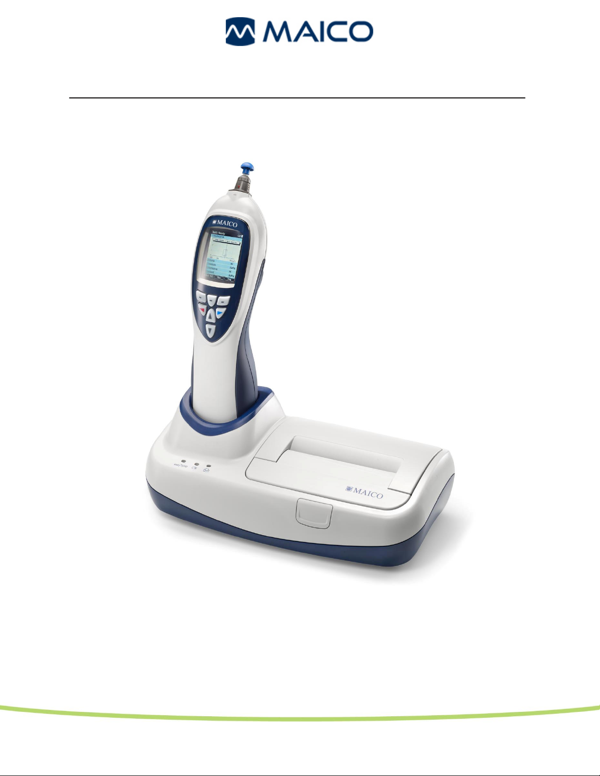
easyTymp® Operating Manual
2
1.2 Safety Notes
The easyTymp® should always be operated in a quiet room with minimal magnetic influence,
to ensure that examinations are not disturbed by external noise.
Electro-medical instruments that emit strong electromagnetic fields (e.g. microwaves,
radiotherapy devices) can affect the operation of the easyTymp®.
Therefore, the operation of these instruments in close proximity to the easyTymp® should be
avoided at all times.
The examination room should have a normal temperature between 15°C/ 59°F and 35°C/ 95°F.
If the instrument has cooled down during transportation, please wait for it to warm up to
room temperature before operation.
MAICO easyTymp® is specified according to EN 60 601-1.
Protection against electrical hazard is guaranteed only when the instrument is
connected to a grounded safety. Please note that during operation, the
instrument should always be connected to a battery-operated or mains-
operated notebook computer that complies with EN 60 601-1 or EN 60 950-
1. In the event that a main cable, connector or wall socket is damaged, please
do not use the instrument under any circumstance.
Attention
PLEASE READ THE ENTIRE MANUAL CAREFULLY BEFORE OPERATING THIS
INSTRUMENT.
Please only use this instrument as described in the manual.
Please familiarize yourself with the instrument and its operation before using.
Should defects or damages be suspected, please do not, under any
circumstances, use or attempt to fix the instrument yourself.
To guarantee that the tympanometer works properly, the instrument has to
be checked and calibrated at least once a year.
The service and calibration must be performed by an authorized service
centre. In accordance with the regulations of the EU medical directive we will
drop our liability if these checks are not done.
The use of non-calibrated tympanometers is not allowed.
Un-calibrated instruments may lead to faulty measurements and sometimes
even damage the hearing of the examinee.
Take note to ensure that all the accessories have been properly connected.
To avoid person-to-person cross contamination of communicable diseases,
parts that come in direct contact with the patient (i.e. eartips) should only be
used one time.
In accordance with the Electronic Equipment Act for disposal of electronic
equipment, the customer is obliged to dispose of the used consumables,
according to appropriate regulation at own cost.