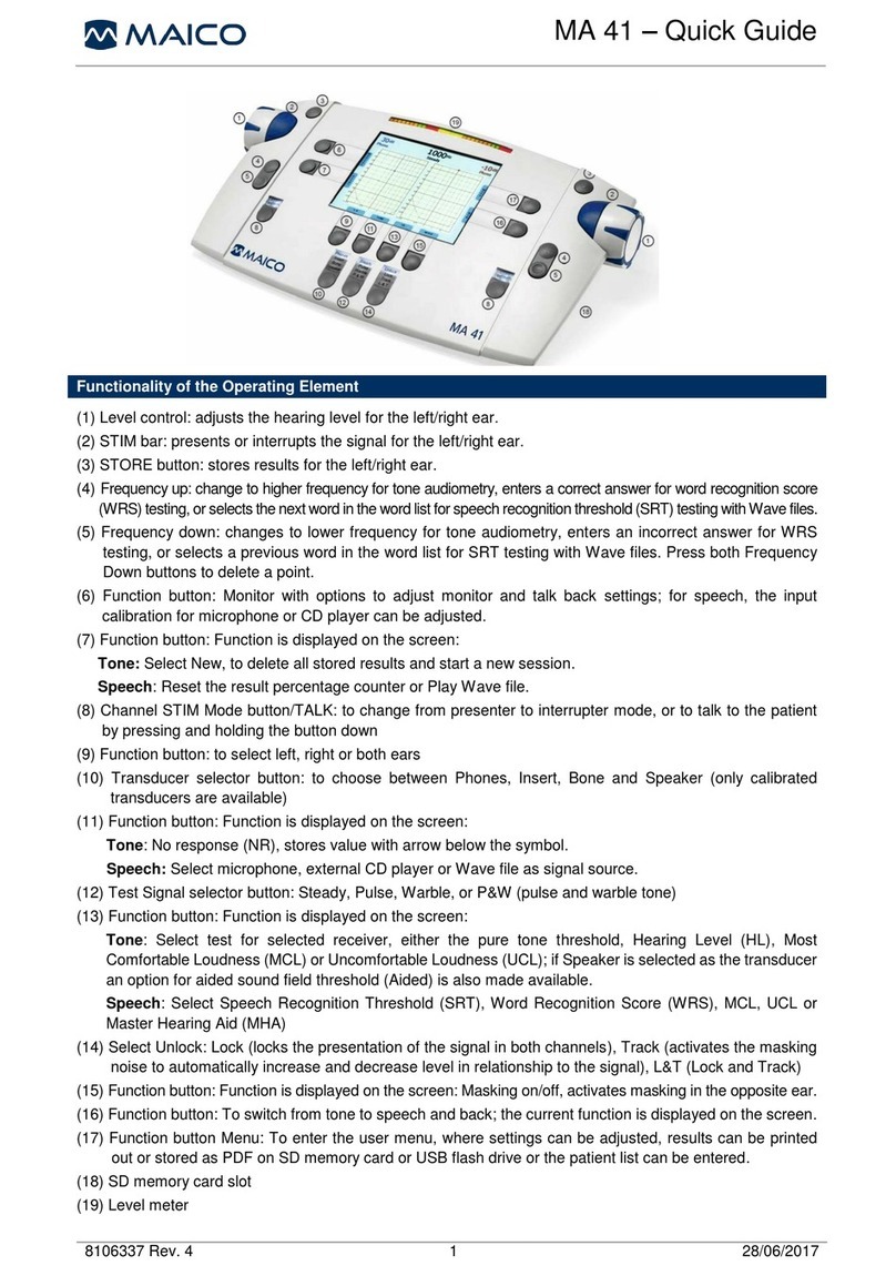
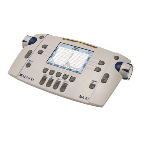
Maico MA 42 User manual

MA 42
Service Manual

Service Manual MA 42
D-0125965 Rev. D
1
18/05/2022
Table of Contents
Introduction...............................................................................................................2
1.1 About this Manual.....................................................................................................2
1.2 About warnings and cautions ...................................................................................2
1.3 General information..................................................................................................2
MA 42 Control Panel .................................................................................................3
2.1 Display and Control Panel........................................................................................3
2.2 Connections...........................................................................................................10
2.3 Pin Assigment ........................................................................................................11
2.4 Setup in a Sound Booth..........................................................................................12
2.5 Establishing a Connection to a PC, Printer or an External Audio Device ................13
Maintenance, Cleaning and Disinfection...............................................................14
3.1 Maintenance...........................................................................................................14
3.2 Cleaning and Disinfection Recommendations ........................................................14
Service and Calibration...........................................................................................15
4.1 Service, Adjustment and Repair.............................................................................15
4.2 Software Calibration...............................................................................................16
Disassembly ............................................................................................................28
Technical Data.........................................................................................................37
6.1 MA 42 Hardware ....................................................................................................37
6.2 Calibration Values and Maximum Levels................................................................42
Spare Parts..............................................................................................................52
History......................................................................................................................58
Service Manual MA 42
D-0125965 Rev. D
2
18/05/2022
Introduction
1.1 About this Manual
This manual is for our diagnostic audiometer. The contents of the manual cover
instrument related data, such as disassembly and calibration. Technical specifications,
along with the parts & accessories list, can be found as appendices in the back of the
manual.
1.2 About warnings and cautions
The warnings and cautions below are applied throughout the manual, indicating the level
of attention required for a given action:
The WARNING label identifies conditions or practices that may
present danger to the patient and/or user.
The CAUTION label identifies conditions or practices that could
result in damage to the equipment
NOTE: Notes help you identify areas of possible confusion and avoid potential problems
duringsystem operation.
1.3 General information
We continuously strive to improve our products and their performance, hence the
specifications in this service manual are subject to change without further notice.
The performance and specifications of our products can only be guaranteed if technical
maintenance is conducted routinely every year. Technical maintenance should be carried
out by qualified personnel authorized by MAICO. We refer to the thoroughly described
calibration procedure in this service manual.
We are happy to receive any inquiries about our products. Our contact details are:
MAICO Diagnostics GmbH
Sickingenstr. 70-71
10553 Berlin
Germany
Tel.: + 49.30.70 71 46-50
Fax: + 49.30.70 71 46-99
Internet: www.maico.biz
MAICO Diagnostics
10393 West 70th St
Eden Prairie, MN 55344
USA
Tel.: 877-722-4490
WARNING
CAUTION

Service Manual MA 42
D-0125965 Rev. D
3
18/05/2022
MA 42 Control Panel
2.1 Display and Control Panel
The main functions of the MA 42 are directly accessible by using the function keys which
are located around the display.
Some of the function keys behave differently depending on how long they are pressed:
Quick Select
Press briefly
Selects directly
e.g.
Advanced Select
Press and hold for 2 s
opens selection menu
with all options shown
e.g.
Figure 1 and 2 show the Display and the Control Panel of the MA42.
NOTE: Buttons that have a filled arrow displayed (i.e., ▲, ►), indicate Advanced Select
is available.
Figure 1

Service Manual MA 42
D-0125965 Rev. D
4
18/05/2022
Figure 2
Table 1 Operating Elements
No.
Key
Information
1
Control Dial
to select (hearing level, test, setting).
2
key
to present/interrupt signal or noise (hearing level) or confirm
selection (test, setting)
3
Skeys
to store single results.
Press for 2 s to store a No Response result.
4
+keys
Tone test: to change to a higher frequency.
SRT test (Wave only): to select the next word.
WRS test: to enter a correct answer.
5
-keys
Tone test: to change to a lower frequency.
SRT test (Wave only): to select the previous word.
WRS test: to enter a wrong answer.
6
Data
Management
Table 2
Data Management
7
Navigation
Table 3
Navigation
8
Test Setup keys
Table 4
Test Setup
9
Selection keys
Table 5
Selection Keys
10
STIM keys
Table 6
STIM/TALK Key and STIM/Monitor Key
11
Numerical
Display
12
Microphone
Buit-in microphone
1
2
2
1
9
3
3
4
4
5
5
8
6
7
10
10
11
12

Service Manual MA 42
D-0125965 Rev. D
5
18/05/2022
Table 2 Data Management
Symbol
Select
Function
Quick Select
to print test report to the default printer.
Advanced
Select
to print test report to the selected printer ( : PDF, :
thermal printer).
Quick Select
to delete all stored results and create a new session.
Advanced
Select
to delete all stored results and create a new session or
to erase last stored value .
If more than 1 value has been stored before a Delete point
window opens. Delete a value using the Control Dial and
the key.
Table 3 Navigation
Symbol
Select
Function
Quick Select
to open the Special Test Menu (Figure 4). Select a special
test using the Control Dial and the key.
Figure 3
Advanced
Select
and press to open the Settings Menu.
Quick Select
to open the Speech Test List.
NOTE: This icon is only shown if wave files are used for
Speech Audiometry.
Advanced
Select
and press to open the Settings Menu OR
press to enter the Special Test Menu.
to switch beween Speech and Tone test.

Service Manual MA 42
D-0125965 Rev. D
6
18/05/2022
Table 4 Test Setup
Symbol
Select
Function
Quick
Select
to change ears (left ↔right channel).
Advanced
Select
to select ear for the left OR right channel. Selection for the
other channel stays the same.
NOTE: This function can be useful if you want to apply
Signal(ToneorSpeech Input)ANDNoisetothesameear.
Tone:
HL
MCL
UCL
Aided
to select the test type.
NOTE: If you want to use the Aided function, you must
first select Speaker as the transducer. Otherwise the
function is grayed out.
Quick
Select
to change Tone and Noise (left ↔right channel).
Advanced
Select
to select Tone or Noise for the left OR right channel
only. The selection of the other channel will not change.
NOTE: This function can be useful if you want to apply the
same stimulus to both ears (binaural presentation).
Speech:
SRT
WRS
MCL
UCL
to select the test type.
Quick
Select
to change Speech Input and Noise (left ↔right channel).
Advanced
Select
to select the Speech Input:
•microphone
•auxiliary 1/2 e.g. CD channel 1/2
•wave channel 1/ 2 or
•Noise
for the left OR right channel only. Theselection of the other
channel will not change.
NOTE: This function can be useful if you want to apply the
same stimulus to both ears (binaural presentation).

Service Manual MA 42
D-0125965 Rev. D
7
18/05/2022
Symbol
Select
Function
Freiburger Speech Test:
Numbers
Words
MCL
UCL
Quick
Select
to select the test type.
Quick
Select
to change Wave Input and Noise (left ↔right channel).
Advanced
Select
to select Wave Input for binaural presentation.
Table 5 Selection Keys
Selection
Function
Transducer
to select the transducer for the left and the right ear (only calibrated
transducers can be selected). Select:
Phones
to select headphones (AC).
Insert
to select insert phones or high frequency headphones (AC).
Bone
to select bone conductor (BC).
NOTE: If you select Bone for one ear, the default or bone
masking transducer is automatically selected for the other
ear. By press and hold for 2 s the opposite transducer can be
changed between Phone and Insert.
Speaker
to select loudspeaker for sound field testing.
NOTE: For specific transducer setup see:
Section 5.11.2
Device Information –Transducers
Tone Type
Steady
to select a steady stimulus.
Pulse
to select pulse stimulus.
Warble
to select warble stimulus.
P & W
to select combined pulse and warble stimulus.
Lock/Track
Function
to select Lock/Track functions. Select:
Unlock
to use neither the Lock nor the Track function.
Lock
to lock the presentation of the signal in both channels.
Track
to automatically increase and decrease channel 1 and 2
levels with the rotation of only one Control Dial.
L & T
to combine Lock and Track function to assist with binaural
testing or masking.

Service Manual MA 42
D-0125965 Rev. D
8
18/05/2022
Table 6 STIM/TALK Key and STIM/Monitor Key
Key
Select
Function
STIM
Talk
Quick Select
STIM: toswitchbetweenPresenter andInterruptermode.
Advanced
Select
Talk:to open the Communication widget (Figure 5)
Figure 4
Talk Forward: Allows tester to provide instruction to the
patient while the headphones are in place.
Increase/decrease the volume by using the Control dial
and the key. The lighted bar/VU meter allows the
examiner to monitor their voice for optimal sound quality.
When speaking, 0is the optimal level.
Talk Back: Allows you to hear the patient through the
internal speaker or monitor headset via an optional talk
back microphone. Increase/decrease the volume or set
the function off by using the Control dial and the key.
The volume dial on the monitor headset must also be
controlled for optimal volume.
Press STIM to close the widget again.
STIM
Monitor
Quick Select
STIM: to switch between Presenter and Interrupter mode.
Advanced
Select
Tone Test:
Monitor: to open the Monitor widget (Figure 6).
Figure 5
Allows you to hear the Tone and Noise stimuli through the
internal speaker or monitor headset. Increase/decrease the
volume or set the function off by using the Control dial and
the Key. The volume dial on the monitor headset must
also be controlled for optimal volume.

Service Manual MA 42
D-0125965 Rev. D
9
18/05/2022
Key
Select
Function
Speech Test:
Monitor: to open the Monitor/Input Calibration widget
(Figure 7).
Figure 6
Monitor: Allows you to hear the Speech Input and Noise
stimuli through the internal speaker or monitor headset via
an optional talk back microphone. Increase/decrease the
volume or set the function off by using the Control dial
and the Key. The volume dial on the monitor headset
must also be controlled for optimal volume.
Input Calibration: Allows you to calibrate the selected
input signal by using the Control dial and the Key.
The optimal level is between -3 and 0 (green area).
Press Monitor to close the widget again.

Service Manual MA 42
D-0125965 Rev. D
10
18/05/2022
2.2 Connections
In order to ensure that the device works properly, it has to be checked and calibrated at
least once every twelve months.
Figure 7
Table 7 Connections on Backside
CONNECTIONS
No
Connection socket
Specification
1
On/Off
Power Switch
2
Power Supply
External Power supply +12V 2A (center +12V)
Model UES24LCP-120200SPA
3
USB 2.0 A Host
4
USB 2.0 B Device
5
Patient Response Switch
2 kΩ 3.3V DC
6
Talk Back Microphone
Input impedance
Min. input level 0 VU
Max. input level 0 VU
3.4 kΩ
212 µVrms 1 kHz
6.6 mVrms 1 kHz
7
Mic (Microphone)
Input impedance
Min. input level 0 VU
Max. input level 0 VU
3.4 kΩ
212 µVrms 1 kHz
6.6 mVrms 1 kHz
8
Monitor Phone
Max voltage level
Load impedance
2.4 Vrms
4 Ωor higher
9
AUX Input
Input impedance
Min. input level 0 VU
Max. input level 0 VU
47 kΩ
16 mVrms 1 kHz
500 mVrms 1 kHz
10
Speaker Left Line
Max. voltage level
Load impedance
3 Vrms
2 kΩor higher
11
Speaker Right Line
Max. voltage level
Load impedance
3 Vrms
2 kΩor higher
12
Bone (Bone Conductor)
Max. voltage level
Load impedance
6 Vrms
3.3 Ωor higher
13
Insert Phone Left
Max. voltage level
Load impedance
3 Vrms
10 Ωor higher
14
Insert Phone Right
Max. voltage level
Load impedance
3 Vrms
10 Ωor higher
15
Phone Left (Headphone)
Max. voltage level
Load impedance
3 Vrms
10 Ωor higher
16
Phone Right (Headphone)
Max. voltage level
Load impedance
3 Vrms
10 Ωor higher
11
13
14
16
15
12
9
10
8
7
6
5
4
2
1
3

Service Manual MA 42
D-0125965 Rev. D
11
18/05/2022
2.3 Pin Assigment
Socket No.
Connector
Pin I
(Inner)
Pin O
(Outer)
2
DC socket
12 V
Ground
Socket No.
USB
3
1. +5 VDC
2. Data -
3. Data +
4. Ground
4
1. +5 VDC
2. Data -
3. Data +
4. Ground
Socket No.
Connector
Pin 1
Pin 2
Pin 3
6
6.3 mm Stereo
6.3 mm Mono
Ground
Signal
-
12, 13, 14,
15, 16
Ground
Signal
-
5
-
7
3.5 mm Stereo
Ground
DC bias
Signal
8, 9
Ground
Right
Left
10,11
RCA
Ground
Signal
-

Service Manual MA 42
D-0125965 Rev. D
12
18/05/2022
2.4 Setup in a Sound Booth
If you connect external equipment (applied parts) to a sound
booth via a common jack panel with common grounding, this can
cause a short circuit in the device. This will lead to severe device
failure.
Installation should be carried out by an authorized MAICO
service technician only.
Check before use that the installation is correct (e.g. after
cleaning).
CAUTION

Service Manual MA 42
D-0125965 Rev. D
13
18/05/2022
2.5 Establishing a Connection to a PC,Printer or an ExternalAudio Device
Infection of the device or the software used with the device can
lead to system failure and data misuse.
Ensurethat your PC is adequately protected againstcyber-attacks.
To transfer data to a PC, establishing a PC connection via USB is required. If the MA 42
is used with office equipment that is not a medical device itself (see Table 8PC
Connection 1), make sure to establish the PC connection in one of the following ways
(see, PC Connection 2, 3 or 4).
In case an external audio device shall be connected proceed accordingly to PC
Connection 3 (if used with an external audio device with power supply) or 4 (if used with
a battery driven external audio device).
Make sure you use only office equipment with the device that
is a medical device itself or meets the requirements of
IEC 60950. If a non-medical device is used within the patient
environment (1.5 m from patient as defined in IEC 60601)
a voltage transformer must beused (exception: a battery driven
laptop is used).
Table 8 PC-Connections
PC CONNECTIONS
PC Connection 1:
Medical device –Medical device
PC Connection 2:
Medical device –Non-Medical device
PC Connection 3:
Medical device –Non-Medical device
PC Connection 4:
Medical device –Laptop (battery-driven)
WARNING
WARNING

Service Manual MA 42
D-0125965 Rev. D
14
18/05/2022
Maintenance, Cleaning and Disinfection
3.1 Maintenance
In order to ensure that the device works properly, it has to be checked and calibrated at
least once every twelve months.
The service and calibration must be performed by your dealer or to a service center
authorized by MAICO.
When returning the device for repairs or calibration it is essential to send the acoustic
transducers with the device. Please include a detailed description of faults. In order to
prevent damage in transit, please use the original packing when returning the device.
3.2 Cleaning and Disinfection Recommendations
It is recommended that parts (device and accessories like headphones, ear cushions)
which come in direct contact with the patient be subjected to standard cleaning and
disinfecting procedure between patients.
Recommendations for cleaning and disinfection of MAICO device presented in this
document are not intended to replace or contradict policies in effect or procedures
required for infection control at the facility.
If there is not a high infection potential, MAICO recommends:
•Before cleaning always switch off and disconnect the device from power supply.
•For cleaning use a lightly dampened cloth with soap water solution
•Disinfect the device and its accessories by wiping the surfaces with wet disinfection
wipes and allow them to take effect for the duration related to the specific
disinfection aim listed in product data sheet of the disinfection product. Please
follow also its instructions for cleaning
•Wipe before and after each patient
•After contamination
•After infectious patients
•Disinfect computer, keyboard, transport trolley etc.:
•once a week
•after contamination
•when polluted
To avoid damage of the device and its accessories, please mind
the following:
Do not autoclave or sterilize.
Do not use the device in the presence of fluid that can come into
contact with any of the electronic components or wiring.
Should the user suspect fluids have contacted the system
components or accessories, the unit should not be used until
deemed safe by a MAICO certified service technician.
Donot usehard or pointed objects onthedeviceor its accessories
Use 70 % isopropyl alcohol only on hard cover surfaces.
CAUTION
CAUTION

Service Manual MA 42
D-0125965 Rev. D
15
18/05/2022
Service and Calibration
This chapter contains calibration standards for the MA 42, Included here is an illustrated
guide of how to calibrate the transducer types used with MA 42.
4.1 Service, Adjustment and Repair
MA 42 can be serviced, adjusted and repaired without losing the validity of the CE-
marking, provided the measuring equipment fulfills the below demands, the adjustment
procedures are followed and staff have the necessary qualifications as approved by
MAICO.
Before any attempt is made to calibrate MA 42, it must have been powered on for 3-5
minutes in an ambient temperature that is both stable and comfortable.
4.1.1 Hardware Calibration
The hardware calibration of MA 42 is typically performed during the production of the
device and therefore does not require adjustment in the field.
4.1.2 Equipment for the Calibration
To ensure proper calibration of audiometric equipment, test instruments must be reliable,
stable and their calibration certified. The minimum requirementsfor calibration equipment are:
- Type 1 sound level meter –Octave band filter set (1/3 octave, range of minimum
125 Hz to 16000 Hz) must meet Type 1 sound level meter (ANSI S1.4). The
sensitivity of the Sound Level Meters must be checked before use with a sound
level calibrator.
- Piston phone or sound level calibrator
- Acoustic couplers:
- NBS–9A (6cc) ANSI/ASA S3.7, or IEC 60318-3, Electroacoustics –Simulators
of human head and ear –Part 3: Acoustic coupler for the calibration of supra-
aural earphones used in audiometry.
- IEC 60318-5, Electroacoustics –Simulators of human head and ear - Part 5:
2 cm³ coupler for the measurement of hearing aids and earphones coupled to
the ear by means of ear inserts
- Calibration reports/sheets to keep track of the measuring results and ensure that
the audiometer meets the requirements.
4.1.3 Calibration of Test Equipment
All test equipment used for the calibration of audiometers is to be calibrated annually.
Calibration of all test equipment is to be performed by a laboratory which is traceable to
the National Institute of Standards and Technology (NIST) or equivalent. Test equipment
calibration documents are to be kept on file.

Service Manual MA 42
D-0125965 Rev. D
16
18/05/2022
4.2 Software Calibration
For the software calibration of the MA42 the following is required.
1. MA42 to a PC with a USB 2.0 cable.
2. MA42 Calibration Tool.
3. Service Code available for approved service partners
4.2.1 Installation of Calibration Tool
Approved service partners will receive the MA42MA52 Calibration.msi file
Step 1: Run msi file with a double click: Windows Installer will open up and prepare the
installation.
From here you follow all the prompts that are requested. Press to continue or abort
with Cancel.

Service Manual MA 42
D-0125965 Rev. D
17
18/05/2022
Step 2a: Chose the folder where you want the Cal Software to be saved or just proceed
with the default folder (recommended) with Next.
or Step 2b: If the SW is already installed you can also repair or remove the Calibration
Tool from the PC, if necessary:

Service Manual MA 42
D-0125965 Rev. D
18
18/05/2022
Step 3:
Click on Install to start the Installation:
Step 4:
Depending on your PC configuration you might get User Account Control request. To
continue confirm with yes:
There after the installation process will start.

Service Manual MA 42
D-0125965 Rev. D
19
18/05/2022
During the installation process a statusbar is visible until the process is complete.
Step 5: Once the Finish button in the Setup Wizard becomes active press it to exit the
setup process.
•IEC 60318-5, Electroacoustics –Simulators of human head and ear - Part 5: 2
cm³ coupler for the measurement of hearing aids and earphones coupled to the
ear by means of ear inserts
•Calibration reports/sheets to keep track of the measuring results and ensure that
the audiometer meets the requirements.
Other manuals for MA 42
5
Table of contents
Other Maico Medical Equipment manuals

Maico
Maico easyTymp User manual

Maico
Maico MA 28 Installation manual

Maico
Maico DRD Ex Series User manual

Maico
Maico MA 25 User manual

Maico
Maico MA 28 User manual

Maico
Maico easyTymp User manual

Maico
Maico ERO SCAN User manual

Maico
Maico MA 41 User manual

Maico
Maico easyScreen User manual

Maico
Maico MB 11 BERAphone User manual
Popular Medical Equipment manuals by other brands

BMB MEDICAL
BMB MEDICAL CARVI user manual

Medirol
Medirol CONTERO M126 user manual

Teladoc Health
Teladoc Health MA-20068 quick start guide

Bort
Bort EpiBasic Sport elbow support manual

Ossur
Ossur Exoform Dorsal Night Splint Instructions for use

TRI-TECH MEDICAL
TRI-TECH MEDICAL MCP100A Installation & operating instructions