Makita CA5000 User manual

CA5000
EN Aluminum Groove Cutter INSTRUCTION MANUAL 6
FR Fraiseuse Alu MANUEL D’INSTRUCTIONS 12
DE Plattenfräse BETRIEBSANLEITUNG 19
IT Scanalatore per alluminio ISTRUZIONI PER L’USO 27
NL Aluminiumgroefzaag GEBRUIKSAANWIJZING 34
ES Ranuradora de Aluminio MANUAL DE
INSTRUCCIONES 41
PT Fresadora de Alumínio MANUAL DE INSTRUÇÕES 48
DA Rilleskærer til aluminium BRUGSANVISNING 55
EL Κόπτης αυλακώσεων σε
αλουμίνιο ΕΓΧΕΙΡΙΔΙΟ ΟΔΗΓΙΩΝ 62
TR Alüminyum Oluk Açma
Makinası KULLANMA KILAVUZU 70

Fig.1
Fig.2
Fig.3
Fig.4
Fig.5
Fig.6
1
2
Fig.7
1
Fig.8
2

1
4
2
3
Fig.9
2
1
Fig.10
1
Fig.11
2
1
3
Fig.12
1
Fig.13
Fig.14
2
1
Fig.15
1
2
3
4
Fig.16
3

1
Fig.17
1
2
3
4
Fig.18
1
Fig.19
2
1
Fig.20
1
2
Fig.21
1
Fig.22
Fig.23
1
Fig.24
4

1
Fig.25
1
Fig.26
1
Fig.27
5

6ENGLISH
ENGLISH (Original instructions)
SPECIFICATIONS
Model: CA5000
Groove cutter blade diameter 118.0 mm
Circular saw blade diameter 165.0 mm
Max. cutting depth (with groove cutter blade) 11.0 mm
Max. cutting depth (with circular saw blade) 36.0 mm
No load speed 2,200 - 6,400 min-1
Overall length 346 mm
Net weight 5.1 kg
Safety class /II
• Duetoourcontinuingprogramofresearchanddevelopment,thespecicationshereinaresubjecttochange
without notice.
• Specicationsmaydifferfromcountrytocountry.
• WeightaccordingtoEPTA-Procedure01/2003
Symbols
Thefollowingshowthesymbolsusedfortheequip-
ment. Be sure that you understand their meaning before
use.
Read instruction manual.
DOUBLEINSULATION
Groove cutter blade
Circular saw blade
OnlyforEUcountries
Donotdisposeofelectricequipment
together with household waste material! In
observanceoftheEuropeanDirective,on
WasteElectricandElectronicEquipment
and its implementation in accordance with
nationallaw,electricequipmentthathave
reached the end of their life must be col-
lected separately and returned to an envi-
ronmentally compatible recycling facility.
Intended use
Thetoolisspeciallyintendedforcuttinggrooveinto
composite boards made from aluminum, plastic, mineral
contained plastic, and similar materials.
Ifthetoolisequippedwithpropercircularsawblade,
the tool can be used for sawing wood and aluminum.
Power supply
Thetoolshouldbeconnectedonlytoapowersupplyof
the same voltage as indicated on the nameplate, and
canonlybeoperatedonsingle-phaseACsupply.They
are double-insulated and can, therefore, also be used
from sockets without earth wire.
Noise
ThetypicalA-weightednoiseleveldeterminedaccord-
ingtoEN60745:
Soundpressurelevel(LpA):82dB(A)
Soundpowerlevel(LWA):93dB(A)
Uncertainty(K):3dB(A)
WARNING: Wear ear protection.
Vibration
Thevibrationtotalvalue(tri-axialvectorsum)deter-
minedaccordingtoEN60745:
Workmode:aluminumcompositematerialgroove
cutting
Vibration emission (ah):2.5m/s2or less
Uncertainty(K):1.5m/s2
Workmode:cuttingwood
Vibration emission (ah,W):2.5m/s2or less
Uncertainty(K):1.5m/s2
Workmode:cuttingmetal
Vibration emission (ah,M):2.5m/s2or less
Uncertainty(K):1.5m/s2
NOTE:
Thedeclaredvibrationemissionvaluehasbeen
measured in accordance with the standard test method
and may be used for comparing one tool with another.
NOTE:
Thedeclaredvibrationemissionvaluemayalso
be used in a preliminary assessment of exposure.
WARNING:Thevibrationemissionduringactual
use of the power tool can differ from the declared
emission value depending on the ways in which the
tool is used.
WARNING: Be sure to identify safety measures
to protect the operator that are based on an estima-
tion of exposure in the actual conditions of use (taking
account of all parts of the operating cycle such as
the times when the tool is switched off and when it is
running idle in addition to the trigger time).

7ENGLISH
EC Declaration of Conformity
For European countries only
MakitadeclaresthatthefollowingMachine(s):
DesignationofMachine:AluminumGrooveCutter
ModelNo./Type:CA5000
ConformstothefollowingEuropeanDirectives:
2006/42/EC
Theyaremanufacturedinaccordancewiththefollowing
standardorstandardizeddocuments:EN60745
Thetechnicalleinaccordancewith2006/42/ECis
availablefrom:
Makita,Jan-BaptistVinkstraat2,3070,Belgium
22.1.2015
Yasushi Fukaya
Director
Makita,Jan-BaptistVinkstraat2,3070,Belgium
General power tool safety warnings
WARNING: Read all safety warnings and
all instructions. Failure to follow the warnings and
instructionsmayresultinelectricshock,reand/or
seriousinjury.
Save all warnings and instruc-
tions for future reference.
Theterm"powertool"inthewarningsreferstoyour
mains-operated (corded) power tool or battery-operated
(cordless) power tool.
Circular saw safety warnings
Cutting procedures
1.
DANGER: Keep hands away from cutting area
and the blade. Keep your second hand on auxil-
iary handle, or motor housing. If both hands are
holding the saw, they cannot be cut by the blade.
2. Do not reach underneath the workpiece.The
guard cannot protect you from the blade below the
workpiece.
3. Adjust the cutting depth to the thickness of
the workpiece.Lessthanafulltoothoftheblade
teeth should be visible below the workpiece.
4. Never hold piece being cut in your hands or
across your leg. Secure the workpiece to a
stable platform. It is important to support the
work properly to minimize body exposure, blade
binding, or loss of control.
►Fig.1
5. Hold the power tool by insulated gripping
surfaces only, when performing an operation
where the cutting tool may contact hidden
wiring or its own cord.Contactwitha"live"wire
will also make exposed metal parts of the power
tool"live"andcouldgivetheoperatoranelectric
shock.
6. When ripping, always use a rip fence or
straight edge guide.Thisimprovestheaccuracy
of cut and reduces the chance of blade binding.
7. Always use blades with correct size and shape
(diamond versus round) of arbour holes.
Blades that do not match the mounting hardware
of the saw will run eccentrically, causing loss of
control.
8. Never use damaged or incorrect blade wash-
ers or bolt.Thebladewashersandboltwere
specially designed for your saw, for optimum
performance and safety of operation.
Kickback causes and related warnings
— kickback is a sudden reaction to a pinched, bound
or misaligned saw blade, causing an uncontrolled
saw to lift up and out of the workpiece toward the
operator;
— when the blade is pinched or bound tightly by the
kerf closing down, the blade stalls and the motor
reaction drives the unit rapidly back toward the
operator;
— if the blade becomes twisted or misaligned in the
cut, the teeth at the back edge of the blade can dig
into the top surface of the wood causing the blade
toclimboutofthekerfandjumpbacktowardthe
operator.
Kickbackistheresultofsawmisuseand/orincorrect
operating procedures or conditions and can be avoided
by taking proper precautions as given below.
1. Maintain a rm grip with both hands on the
saw and position your arms to resist kickback
forces. Position your body to either side of the
blade, but not in line with the blade.Kickback
couldcausethesawtojumpbackwards,but
kickback forces can be controlled by the operator,
if proper precautions are taken.
2.
When blade is binding, or when interrupting a
cut for any reason, release the trigger and hold
the saw motionless in the material until the
blade comes to a complete stop. Never attempt
to remove the saw from the work or pull the saw
backward while the blade is in motion or kick-
back may occur. Investigate and take corrective
actions to eliminate the cause of blade binding.
3. When restarting a saw in the workpiece, centre
the saw blade in the kerf and check that saw
teeth are not engaged into the material. If saw
blade is binding, it may walk up or kickback from
the workpiece as the saw is restarted.
4. Support large panels to minimise the risk of
blade pinching and kickback.Largepanelstend
to sag under their own weight. Supports must be
placed under the panel on both sides, near the line
of cut and near the edge of the panel.
►Fig.2
►Fig.3
5. Do not use dull or damaged blades.
Unsharpenedorimproperlysetbladesproduce
narrow kerf causing excessive friction, blade
binding and kickback.
6. Blade depth and bevel adjusting locking levers
must be tight and secure before making cut. If
bladeadjustmentshiftswhilecutting,itmaycause
binding and kickback.
7. Use extra caution when sawing into existing
walls or other blind areas.Theprotrudingblade
maycutobjectsthatcancausekickback.

8ENGLISH
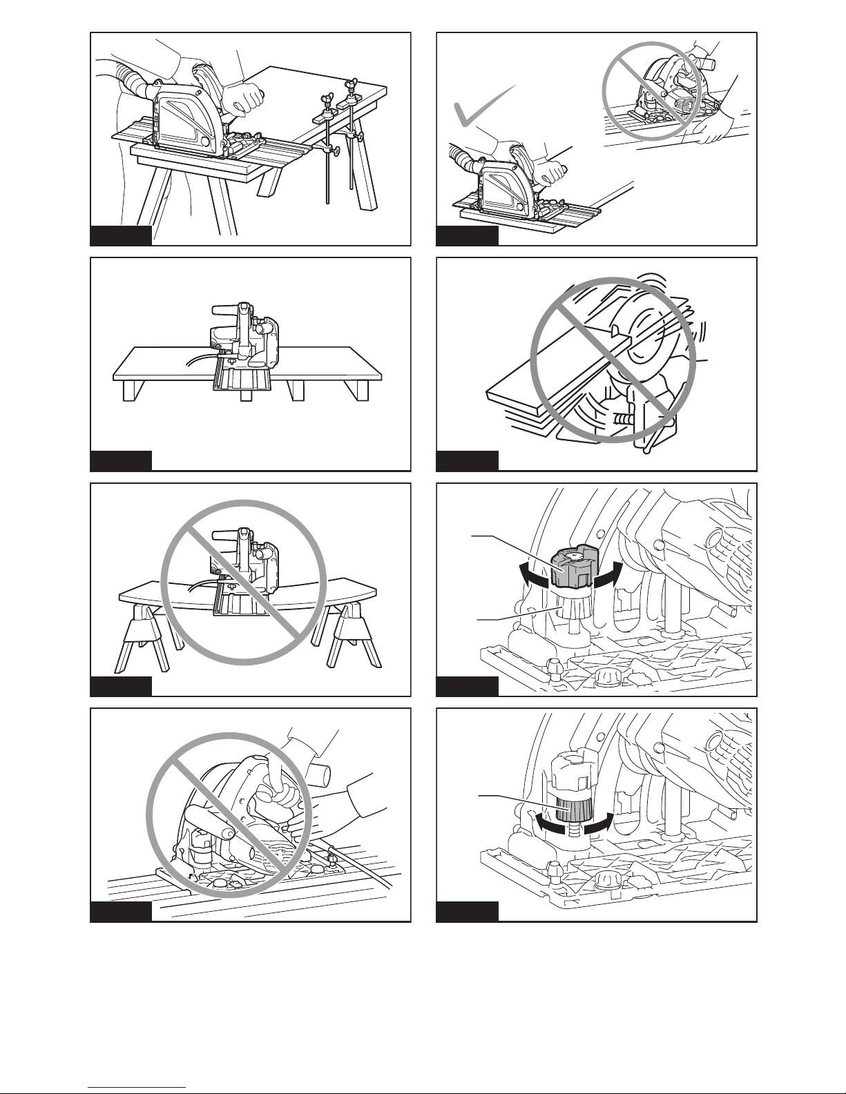
8. ALWAYS hold the tool rmly with both hands.
NEVER place your hand, leg or any part of your
body under the tool base or behind the saw,
especially when making cross-cuts. If kickback
occurs,thesawcouldeasilyjumpbackwardsover
yourhand,leadingtoseriouspersonalinjury.
►Fig.4
9. Never force the saw. Push the saw forward at a
speed so that the blade cuts without slowing.
Forcing the saw can cause uneven cuts, loss of
accuracy, and possible kickback.
Guard function
1. Check guard for proper closing before each
use. Do not operate the saw if guard does not
move freely and enclose the blade instantly.
Never clamp or tie the guard so that the blade
is exposed. If saw is accidentally dropped, guard
may be bent. Check to make sure that guard
moves freely and does not touch the blade or any
other part, in all angles and depths of cut.
2. Check the operation and condition of the
guard return spring. If the guard and the spring
are not operating properly, they must be ser-
viced before use. Guard may operate sluggishly
due to damaged parts, gummy deposits, or a
build-up of debris.
3.
Assure that the base plate of the saw will not
shift while performing the “plunge cut” when the
blade bevel setting is not at 90 °. Blade shifting
sideways will cause binding and likely kick back.
4. Always observe that the guard is covering the
blade before placing saw down on bench or
oor.Anunprotected,coastingbladewillcause
the saw to walk backwards, cutting whatever is in
its path. Be aware of the time it takes for the blade
to stop after switch is released.
Additional safety warnings
1.
Use extra caution when cutting damp wood, pres-
sure treated lumber, or wood containing knots.
Maintain smooth advancement of tool without decrease
in blade speed to avoid overheating the blade tips.
2. Do not attempt to remove cut material when
blade is moving. Wait until blade stops before
grasping cut material. Blades coast after turn off.
3. Avoid cutting nails. Inspect for and remove all
nails from lumber before cutting.
4. Place the wider portion of the saw base on
that part of the workpiece which is solidly
supported, not on the section that will fall off
when the cut is made. If the workpiece is short
or small, clamp it down. DO NOT TRY TO HOLD
SHORT PIECES BY HAND!
►Fig.5
5. Before setting the tool down after completing a
cut, be sure that the guard has closed and the
blade has come to a complete stop.
6. Never attempt to saw with the circular saw
held upside down in a vise. This is extremely
dangerous and can lead to serious accidents.
►Fig.6
7.
Some material contains chemicals which may be
toxic. Take caution to prevent dust inhalation and
skin contact. Follow material supplier safety data.
8. Do not stop the blades by lateral pressure on
the saw blade.
9. Do not use any abrasive wheels.
10. Only use the saw blade with the diameter that
is marked on the tool or specied in the man-
ual.Useofanincorrectlysizedblademayaffect
the proper guarding of the blade or guard opera-
tionwhichcouldresultinseriouspersonalinjury.
11.
Keep blade sharp and clean. Gum and wood pitch
hardened on blades slows saw and increases poten-
tialforkickback.Keepbladecleanbyrstremoving
it from tool, then cleaning it with gum and pitch
remover, hot water or kerosene. Never use gasoline.
12. Wear a dust mask and hearing protection when
use the tool.
SAVE THESE INSTRUCTIONS.
WARNING: DO NOT let comfort or familiarity
with product (gained from repeated use) replace
strict adherence to safety rules for the subject
product. MISUSE or failure to follow the safety
rules stated in this instruction manual may cause
serious personal injury.
FUNCTIONAL
DESCRIPTION
CAUTION: Always be sure that the tool is
switched off and unplugged before adjusting or
checking function on the tool.
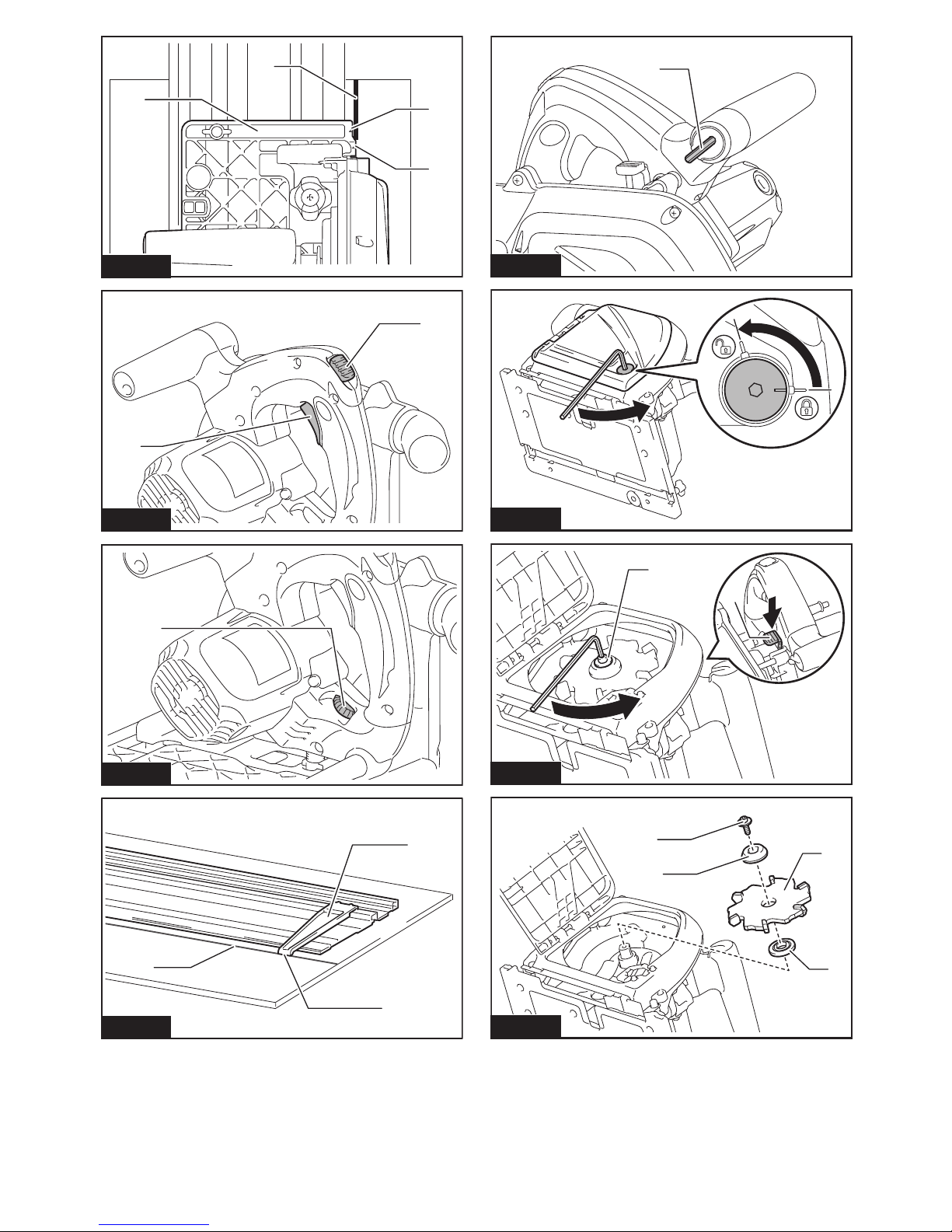
Quick stop for 3, 4, or 6 mm board
thickness groove cutting
Byturningthequickstop,youcanchoosetheappro-
priate depth of groove cutting for 3, 4, or 6 mm board
thickness swiftly.
Thenumber,seenfromthehandleside,indicatesthe
workpiece board thickness.
Forneadjustmentofdepthofgroove,usethedepth
adjustingknob.
►Fig.7: 1. Quick stop 2.Depthadjustingknob
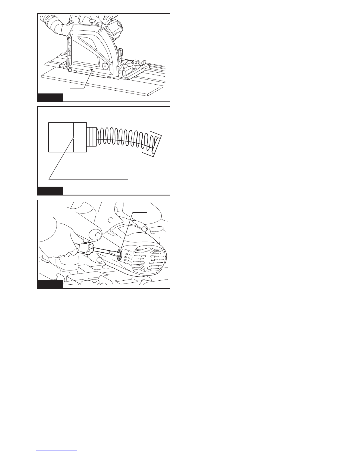
0 mm depth is set properly when the tool is shipped
from the factory, but if you changed the depth of groove
bytheadjustingknob,renethe0mmdepthasfollows:
1. Turnthequickstopto0mm.
2. Turnthedepthadjustingknobtoadjustthedepth.
3. Make sure that the blade does not make any
contact with work piece.
4. Holdthetoolrmlywithonehandonthefrontgrip
andtheotheronthetoolhandle.Pushinthelock-off
button, and turn the tool on.
5. Slowly press down the saw head fully, and check
whether the groove cutter blade does not contacts but
almost touches the workpiece. If not, stop the tool and
wait until the groove cutter blade stops completely, and
adjustthedepthbyturningthedepthadjustingknob
again.

9ENGLISH
Adjusting depth of cut
Toadjustdepthofcut,turnthedepthadjustingknob.
For deeper cut, turn it clockwise. For shallower cut, turn
it counterclockwise.
►Fig.8: 1.Depthadjustingknob
Sighting
Triangularmarkonthebaseindicatesthecenterofthe
groove cutter blade.
Whenusingwithgroovecutterblade,aligntheoutside
triangular mark with the cutting line.
Whenusingwithcircularsawblade(optionalaccessory),
align the inside triangular mark with the cutting line.
►Fig.9: 1. Base 2. Outside triangular mark 3. Inside
triangular mark 4. Cutting line
Switch action
CAUTION: Before plugging in the tool, always
check to see that the switch trigger actuates
properly and returns to the "OFF" position when
released.
Topreventtheswitchtriggerfrombeingaccidentally
pulled, a lock-off button is provided.
Tostartthetool,pushinthelock-offbuttonandpullthe
switch trigger.
Release the switch trigger to stop.
►Fig.10: 1.Lock-offbutton2. Switch trigger
Speed adjusting dial
CAUTION: The speed adjusting dial is not for
using low speed rated blades but for obtaining a
speed which is suitable to material of workpiece.
Useonlybladeswhichareratedforatleastthemaxi-
mumnoloadspeedstatedintheSPECIFICATIONS.
CAUTION:Thespeedadjustingdialcanbe
turned only as far as 6 and back to 1. Do not force it
past 6 or 1, or the speed adjusting function may
no longer work.
Thetoolspeedcanbeadjustedbyturningtheadjusting
dial. Higher speed is obtained when the dial is turned in
the direction of number 6; lower speed is obtained when
it is turned in the direction of number 1.
Refer to the table to select the proper speed for the
workpiece to be cut. However, the appropriate speed
may differ with the type or thickness of the workpiece. In
general, higher speeds will allow you to cut workpieces
faster but the service life of the blade will be reduced.
Number min-1
12,200
22,700
33,800
44,900
56,000
66,400
►Fig.11: 1.Speedadjustingdial
Guide plate
For aligning the guide rail (optional accessory) with the
cutting line, use the guide plate.
►Fig.12: 1. Guide plate 2.Plateedge3. Cutting line
1. Set the guide plate onto the guide rail near from
thecuttingstartpoint.Theplateedgerepresentsthe
centerofthegroovecutterblade.Aligntheplateedge
with the cutting line.
2. Then,setagaintheguideplateontheguiderail
nearthecuttingendpoint.Andaligntheplateedgewith
the cutting line again.
Other features
Thetoolsequippedwithelectronicfunctionareeasyto
operate because of the following features.
Overload protector
Whentheloadonthetoolexceedsadmissiblelevels,
power to the motor is reduced to protect the motor from
overheating.Whentheloadreturnstoadmissiblelev-
els, the tool will operate as normal.
Constant speed control
Electronicspeedcontrolforobtainingconstantspeed.
Possibletogetnenish,becausetherotatingspeedis
kept constant even under load condition.
Soft start feature
Soft start because of suppressed starting shock.
ASSEMBLY
CAUTION: Always be sure that the tool is
switched off and unplugged before carrying out
any work on the tool.
Hex wrench storage
Hexwrenchisstoredonthetool.Toremovehex
wrench,justpullitout.
Toinstallhexwrench,placeitonthegripandinsertitas
far as it goes.
►Fig.13: 1. Hex wrench
Removing or installing groove
cutter blade
CAUTION:
Do not use blades which do not comply
with the characteristics specied in these instructions.
CAUTION: Use only blades which are rated
for at least the maximum no load speed stated in
the SPECIFICATIONS.
CAUTION: Be sure the blade is installed with
teeth pointing up at the front of the tool.
CAUTION: Use only the Makita wrench to
install or remove the blade.

10 ENGLISH
Toremovethegroovecutterblade,performfollowing
steps:
1. Liedownthetoolasthemotorhousingandthe
basetouchingtheground.Theninsertthehexwrench
into the hex hole, push it in, and open the blade case
door by turning the hex wrench.
►Fig.14
2. Presstheshaftlockfullysothatthebladedoes
not revolve, then loosen the hex bolt counterclockwise
with the wrench.
►Fig.15: 1. Shaft lock 2. Hex bolt
3. Removethehexbolt,outerangeandblade.
►Fig.16: 1. Hex bolt 2.Outerange3. Groove cutter
blade 4.Innerange
Toinstalltheblade,followtheremovalprocedurein
reverse. Be sure to tighten the hex bolt clockwise
securely.Andclosethebladecasedoorafterinstalling
the blade.
Whenchangingblade,makesuretoalsocleanthe
guard of accumulated sawdust and chips as discussed
in the Maintenance section. Such efforts do not replace
the need to check guard operation before each use.
Using circular saw blade
Optional accessory
NOTE: In case using circular saw blade, the skirt is
not needed and it structually can not be installed.
Remove the skirt when using the circular saw blade.
Toinstallthecircularsawblade(optionalaccessory),
performthefollowingsteps:
1. Remove two bolts, and remove the skirt.
►Fig.17: 1. Skirt
2. Remove the groove cutter blade.
3. Slide in the circular saw blade from the opening
which the skirt had covered.
4. Install the circular saw blade in the same way as
thegroovecutterblade.Andclosethebladecasedoor
after installing the blade.
►Fig.18: 1. Hex bolt 2.Outerange3. Circular saw
blade 4.Innerange
5. Adjustdepthofcutbyturningthedepthadjusting
knob.
Rip fence (guide rule)
Optional accessory
CAUTION: Do not use the rip fence with the
groove cutter blade.Usetheripfenceonlywhen
using the tool with the circular saw blade (optional
accessory).
►Fig.19: 1. Rip fence (guide rule)
Thehandyripfenceallowsyoutodoextra-accurate
straight cuts. Simply slide the rip fence up snugly
against the side of the workpiece and secure it in
position with the screws on the front and the back of
the base. It also makes repeated cuts of uniform width
possible.
Overturning the rip fence (guide rule) also works as a
sub base for the tool.
Stopper for 2 to 3 mm depth of
cut when using circular saw blade
(optional accessory) and guide rail
(optional accessory)
►Fig.20: 1. Stopper 2. Red mark
Thistoolhasthestopperfor2to3mmdepthofcut
on the gear housing aside the rear handle when using
guide rail.
Splinter on the workpiece can be avoided by making a
passofthe2to3mmrstcutandthenmakeanother
pass of usual cut.
First, push in the stopper toward the circular saw blade
for obtaining 2 to 3 mm depth of cut.
Thenpullthebuttonbackforperformingfreedepthof
cut.
Make sure that the stopper is released and the red mark
can be seen for groove cutting operation.
Connecting a vacuum cleaner
For groove cutting operation, connect a Makita vacuum
cleaner to your tool.
Connect a hose of the vacuum cleaner to the dust port.
►Fig.21: 1. Vacuum cleaner 2.Dustport
OPERATION
CAUTION:Alwaysuseafrontgripandrear
handleandrmlyholdthetoolbybothfrontgripand
rear handle during operations.
Guide rail
Optional accessory
Alwaysusetheguiderailforgroovecuttingoperation.
Placethetoolontherearendoftheguiderail.
Turntwoadjustingscrewsonthetoolbasesothatthe
tool slides smoothly without a clatter.
►Fig.22: 1.Adjustingscrews
Groove cutting
CAUTION: Be sure to move the tool forward
in a straight line gently. Forcing or twisting the tool
may result in overheating the motor and dangerous
kickback,possiblycausingsevereinjury.
CAUTION: Never approach any part of your
body under the tool base when section cutting,
especially at starting.Doingsomaycauseserious
personalinjuries.Thebladeisexposedunderthetool
base.
CAUTION: Use eye protection to avoid injury.
CAUTION: For groove cutting operation,
always connect the tool to a vacuum cleaner.
CAUTION: Hold the tool rmly. The tool is
provided with both a front grip and rear handle.
Use both to best grasp the tool. If both hands are
holding saw, they cannot be cut by the blade.

11 ENGLISH
►Fig.23
1. Adjustthedepthofcut.
2. Set the tool on the guide rail.
3. Aligntheguiderailalongthecuttinglinewithusing
the guide plate. Make sure that the blade does not
make any contact with workpiece.
4. Pushinthelock-offbuttonandturnthetoolon,
and wait until the blade attains full speed.
5. Pressdownthetoolslowlytothepresetdepthof
cut, and simply move the tool forward over the work-
piecesurface,keepingitatandadvancingsmoothly
until the cutting is completed.
6. Whencuttingiscomplete,releaseswitch,waitfor
blade to stop and then withdraw tool.
Togetcleancuts,keepyourcuttinglinestraightand
your speed of advance uniform. If the cut fails to prop-
erly follow your intended cut line, do not attempt to
turn or force the tool back to the cut line.Doingso
may bind the blade and lead to dangerous kickback and
possibleseriousinjury.
Plunge cutting (Cutting-out)
WARNING: To avoid a kickback, be sure to
observe the following instructions.
1. Placethetoolontheguiderailwiththerearedge
oftoolbaseagainstaxedstoporequivalentwhichis
clamped on the guide rail.
►Fig.24: 1. Fixed stop
2. Holdthetoolrmlywithonehandonthefrontgrip
andtheotheronthetoolhandle.Pushinthelock-off
button, and turn the tool on, then wait until the blade
attains full speed.
3. Pressdownthesawheadslowlytothepreset
depth of cut, and move the tool forward to the desired
plunge position.
NOTE:Thetriangularmarkonthebladecaseshows
the approximate center of the blade.
►Fig.25: 1.Triangularmark
MAINTENANCE
CAUTION: Always be sure that the tool is
switched off and unplugged before attempting to
perform inspection or maintenance.
CAUTION: Clean out the guard to ensure
there is no accumulated sawdust and chips
which may impede the operation of the guarding
system.Adirtyguardingsystemmaylimittheproper
operation which could result in serious personal
injury.Themosteffectivewaytoaccomplishthis
cleaning is with compressed air. If the dust is being
blown out of the guard, be sure the proper eye
and breathing protection is used.
NOTICE: Never use gasoline, benzine, thinner,
alcohol or the like. Discoloration, deformation or
cracks may result.
Replacing carbon brushes
►Fig.26: 1.Limitmark
Check the carbon brushes regularly.
Replace them when they wear down to the limit mark.
Keepthecarbonbrushescleanandfreetoslipinthe
holders. Both carbon brushes should be replaced at the
sametime.Useonlyidenticalcarbonbrushes.
1. Useascrewdrivertoremovethebrushholder
caps.
2. Takeouttheworncarbonbrushes,insertthenew
ones and secure the brush holder caps.
►Fig.27: 1. Brush holder cap
TomaintainproductSAFETYandRELIABILITY,
repairs,anyothermaintenanceoradjustmentshould
beperformedbyMakitaAuthorizedorFactoryService
Centers, always using Makita replacement parts.
OPTIONAL
ACCESSORIES
CAUTION: These accessories or attachments
are recommended for use with your Makita tool
specied in this manual.Theuseofanyother
accessories or attachments might present a risk of
injurytopersons.Onlyuseaccessoryorattachment
for its stated purpose.
If you need any assistance for more details regard-
ing these accessories, ask your local Makita Service
Center.
• Guiderail
• 90°groovecutterblade
• 135°groovecutterblade
• Guideplate
• Circularsawblade
• Ripfence(Guiderule)
• Clamp
• Hexwrench
• Sheetsetforguiderail
• Rubbersheetsetforguiderail
• Positionsheetforguiderail
• Bevelguideset
NOTE: Some items in the list may be included in the
toolpackageasstandardaccessories.Theymay
differ from country to country.

12 FRANÇAIS
FRANÇAIS (Instructions originales)
SPÉCIFICATIONS
Modèle : CA5000
Diamètredelalamedefraiseàrainurer 118,0 mm
Diamètredelalamedesciecirculaire 165,0 mm
Profondeurmaximumdecoupe(aveclamedefraiseàrainurer) 11,0 mm
Profondeurmaximumdecoupe(aveclamedesciecirculaire) 36,0 mm
Vitesseàvide 2 200 - 6 400 min-1
Longueurtotale 346 mm
Poidsnet 5,1 kg
Catégorie de sécurité /II
• Étantdonnél’évolutionconstantedenotreprogrammederechercheetdedéveloppement,lesspécications
contenuesdanscemanuelsontsujettesàmodicationsanspréavis.
• Lesspécicationspeuventvariersuivantlespays.
• PoidsselonlaprocédureEPTA01/2003
Symboles
Vous trouverez ci-dessous les symboles utilisés pour
l’appareil.Veillezàcomprendreleursignicationavant
toute utilisation.
Lirelemoded’emploi.
DOUBLEISOLATION
Lamedefraiseàrainurer
Lamedesciecirculaire
Uniquementpourlespaysdel’Union
européenne
Nepasjeterlesappareilsélectriquesavec
lesorduresménagères!Conformément
àladirectiveeuropéennerelativeaux
déchetsd’équipementsélectriqueset
électroniquesainsiqu’àsonapplication
en conformité avec les lois nationales,
lesappareilsélectriquesquiontatteintla
ndeleurduréedeservicedoiventêtre
collectésséparémentetrenvoyésàun
établissement de recyclage respectueux
del’environnement.
Utilisations
Cet outil est spécialement conçu pour couper des
rainuresdanslesplanchescompositesfabriquéesen
aluminium,plastique,plastiqueissudematièresminé-
ralesetmatièressimilaires.
Sil’outilestéquipéd’unelamedesciecirculaire
adaptée,ilpeutêtreutilisépourscierduboisetde
l’aluminium.
Alimentation
L’outilnedevraêtreraccordéqu’àunealimentation
delamêmetensionquecellequiguresurlaplaque
signalétique,etilnepourrafonctionnerquesurun
courant secteur monophasé. Réalisé avec une double
isolation,ilpeutdecefaitêtrealimentéparuneprise
sansmiseàlaterre.
Bruit
NiveaudebruitpondéréAtypique,déterminéselon
EN60745:
Niveaudepressionsonore(LpA):82dB(A)
Niveaudepuissancesonore(LWA):93dB(A)
Incertitude(K):3dB(A)
AVERTISSEMENT : Portez un serre-tête
antibruit.
Vibrations
Valeur totale de vibrations (somme de vecteur triaxial)
déterminéeselonEN60745:
Modedetravail:rainuragedematériauxcompositesen
aluminium
Émissiondevibrations(ah):2,5m/s2ou moins
Incertitude(K):1,5m/s2
Modedetravail:coupedebois
Émissiondevibrations(ah,W):2,5m/s2ou moins
Incertitude(K):1,5m/s2
Modedetravail:découpedemétal
Émissiondevibrations(ah, M):2,5m/s2ou moins
Incertitude(K):1,5m/s2
NOTE :Lavaleurd’émissiondevibrationsdéclarée
aétémesuréeconformémentàlaméthodedetest
standardetpeutêtreutiliséepourcomparerlesoutils
entre eux.
NOTE :Lavaleurd’émissiondevibrationsdéclarée
peutaussiêtreutiliséepourl’évaluationpréliminaire
del’exposition.

13 FRANÇAIS
AVERTISSEMENT :L’émissiondevibrations
lorsdel’usageréeldel’outilélectriquepeutêtre
différentedelavaleurd’émissiondéclarée,suivantla
façondontl’outilestutilisé.
AVERTISSEMENT :Lesmesuresdesécuritéà
prendrepourprotégerl’utilisateurdoiventêtrebasées
suruneestimationdel’expositiondansdescondi-
tionsréellesd’utilisation(entenantcomptedetoutes
lescomposantesducycled’utilisation,commepar
exemplelemomentdesamisehorstension,lorsqu’il
tourneàvideetlemomentdesondéclenchement).
Déclaration de conformité CE
Pour les pays européens uniquement
Makitadéclarequelaoulesmachinessuivantes:
Désignationdelamachine:FraiseuseAlu
N°demodèle/Type:CA5000
sontconformesauxDirectiveseuropéennessuivantes:
2006/42/CE
etsontfabriquéesconformémentauxnormesouaux
documentsnormaliséssuivants:EN60745
Ladocumentationtechniqueconformeàlanorme
2006/42/CEestdisponibleauprèsde:
Makita,Jan-BaptistVinkstraat2,3070,Belgique
22.1.2015
Yasushi Fukaya
Directeur
Makita,Jan-BaptistVinkstraat2,3070,Belgique
Consignes de sécurité générales
pour outils électriques
AVERTISSEMENT : Lisez toutes les
consignes de sécurité et toutes les instructions. Il
yarisqued’électrocution,d’incendieet/oudegraves
blessures si les mises en garde et les instructions ne
sont pas respectées.
Conservez toutes les mises en
garde et instructions pour réfé-
rence ultérieure.
Leterme«outilélectrique»danslesavertissements
faitréférenceàl’outilélectriquealimentéparlesecteur
(aveccordond’alimentation)ouàl’outilélectriquefonc-
tionnantsurbatterie(sanscordond’alimentation).
Consignes de sécurité pour scie
circulaire
Procédures de coupe
1.
DANGER : Gardez vos mains à l’écart de la zone
de coupe et de la lame. Laissez votre deuxième main
sur la poignée auxiliaire ou le carter du moteur.La
lamenerisquerapasdevouscouperlesmainssivous
les utilisez toutes les deux pour tenir la scie.
2. Ne placez aucune partie de votre corps sous la
pièce à travailler.Lecarterdeprotectionnepeut
pasprotégerl’utilisateurdelalamesouslapièce.
3. Réglez la profondeur de coupe suivant l’épais-
seur de la pièce à travailler.Lapartiedelalame
visiblesouslapièceàtravaillerdoitêtremoindre
qu’unedentdelamecomplète.
4. Ne tenez jamais la pièce avec les mains ou
contre la jambe. Immobilisez la pièce contre
une surface stable.Ilestimportantquelapièce
soitsoutenuecorrectementpourminimiserl’ex-
position du corps, les pincements de lame et les
pertes de maîtrise.
►Fig.1
5. Saisissez l’outil électrique uniquement par
ses surfaces de poigne isolées lorsque vous
effectuez des travaux au cours desquels l’outil
tranchant peut entrer en contact avec des ls
cachés ou avec le cordon d’alimentation de
l’outil.Lecontactavecunl«soustension»
mettraégalement«soustension»lesparties
métalliquesexposéesdel’outilélectrique,pouvant
ainsicauserunchocélectriquechezl’utilisateur.
6. Lors du sciage en long, utilisez toujours un
guide longitudinal ou un guide de chant.La
coupeserapluspréciseetcelaréduiralesrisques
de pincement de la lame.
7. Utilisez toujours des lames dont l’orice
central est de taille et de forme (diamantée ou
circulaire) appropriée.Silalameutiliséen’est
pasconçuepourlascie,elletournerademanière
excentriqueetvousperdrezlamaîtrisedel’outil.
8. N’utilisez jamais de rondelles ou boulons
de la lame endommagés ou inadéquats.Les
rondelles et le boulon de la lame ont été conçus
exclusivementpourvotrescie,and’assurerune
performance optimale et une utilisation sûre.
Causes des chocs en retour et avertissements
concernant ces derniers
— le choc en retour est une réaction soudaine de
l’outillorsquelalamedescieestcoincée,pincée
ou désalignée, et la scie, hors de contrôle, se
soulèvealorsetquittelapièceensedirigeant
versl’utilisateur;
— lorsquelalamesecoinceouestpincéeparletrait
desciequiserefermesurelle,lalamesebloque
etlaréactiondumoteurentraînelaprojectionde
l’outilàgrandevitesseversl’utilisateur;
— silalamesetordousedésaligneparrapportà
lalignedecoupe,lesdentsarrièrerisquentde
s’enfoncerdanslasurfaceduboisetlalamede
quitterletraitdescieenreculantbrusquement
versl’utilisateur.
Lechocenretourestlerésultatd’unemauvaiseuti-
lisation de la scie et/ou de procédures ou conditions
d’utilisationincorrectes.Onpeutl’éviterenprenantdes
précautionsadéquates,commeindiquéci-dessous:
1. Maintenez une poigne ferme à deux mains
sur la scie, et placez vos bras de sorte qu’ils
puissent résister à la force du choc en retour.
Placez-vous d’un côté ou de l’autre de la lame,
jamais dans sa ligne de coupe.Lechocen
retourpeutfairebondirlascieversl’arrière,mais
laforceduchocenretourpeutêtremaîtriséepar
l’utilisateurenprenantlesprécautionsadéquates.
2.
Si la lame se pince ou si vous interrompez la
coupe pour une raison quelconque, libérez la
gâchette et maintenez la scie immobile dans

14 FRANÇAIS
le matériau jusqu’à l’arrêt complet de la lame.
N’essayez jamais de retirer la scie de la pièce
ou de la faire reculer alors que la lame tourne
encore, sous peine de provoquer un choc en
retour.Identiezlacausedupincementdelalame
et prenez les mesures correctives pour y remédier.
3.
Avant de redémarrer la scie dans la pièce, cen-
trez la lame de scie dans le trait de scie et assu-
rez-vous que les dents ne pénètrent pas dans le
matériau. Si la lame de scie se pince au moment
duredémarragedelascie,ellerisquederemonter
jusqu’àl’utilisateuroudecauserunchocenretour.
4.
Placez un dispositif de soutien sous les grands
panneaux pour réduire les risques de pincement
de la lame et de choc en retour.Lespanneauxde
grandedimensiononttendanceàs’affaissersous
leurproprepoids.Dessupportsdoiventêtreins-
talléssouslepanneau,desdeuxcôtés,prèsdela
lignedecoupeetprèsduborddupanneau.
►Fig.2
►Fig.3
5. N’utilisez pas des lames émoussées ou
endommagées.Leslamesmalaffûtéesoumal
posées produisent un trait de scie étroit, entraî-
nant une friction excessive, le pincement de la
lame et un choc en retour.
6. Les leviers de verrouillage de la profondeur
de coupe et du réglage de coupe en biseau
doivent être serrés de manière ferme et sûre
avant de procéder à la coupe.Ilyarisquede
pincement et de choc en retour si les réglages de
la lame changent pendant la coupe.
7. Soyez tout particulièrement prudent lorsque
vous sciez dans un mur ou autre surface der-
rière laquelle peuvent se trouver des objets
non visibles.Lalamepeutcauserunchocen
retourenentrantencontactaveccesobjets.
8. Tenez TOUJOURS l’outil fermement à deux
mains. Ne placez JAMAIS la main, la jambe
ou toute autre partie du corps sous la base
de l’outil ou derrière la scie, particulièrement
lors de coupes transversales.Encasdechoc
en retour, la scie pourrait facilement bondir vers
l’arrièreetpassersurvotremain,vousinigeant
une blessure grave.
►Fig.4
9. Ne forcez jamais la scie. Faites avancer la scie
à une vitesse permettant à la lame de tourner
sans perte de vitesse.Lefaitdeforcerlascie
peut résulter en des coupes inégales, une perte
de précision et un choc en retour.
Fonctionnement du carter de protection
1. Avant chaque utilisation, assurez-vous que le
carter de protection ferme bien. N’utilisez pas
la scie si le carter de protection ne se déplace
pas librement et ne se referme pas immédia-
tement sur la lame. Évitez d’immobiliser ou
de xer le carter de protection en exposant
la lame.Lecarterdeprotectionrisquedepliersi
vouslâchezlascieparaccident.Assurez-vous
quelecarterdeprotectionsedéplacelibrement
sans entrer en contact avec la lame ou toute autre
partiedel’outil,etcequelquesoitl’angleoula
profondeur de coupe.
2. Vériez le fonctionnement et l’état du ressort
du carter de protection. Le carter de protection
et le ressort doivent être réparés avant l’utili-
sation s’ils ne fonctionnent pas correctement.
Lefonctionnementducarterdeprotectionpeut
êtreralentipardespiècesendommagées,des
dépôtsgluantsoul’accumulationdedébris.
3. Assurez-vous que le socle de la scie ne se
déplace pas lorsque vous effectuez une
« coupe en plongée » alors que le réglage pour
la coupe en biseau de la lame n’est pas sur
90°.Unelamesedéplaçantdecôtéprésenteun
risquedepincementetdechocenretour.
4.
Assurez-vous toujours que le carter de protection
recouvre la lame avant de poser la scie sur l’établi
ou le plancher.Unelamenonprotégéeetcontinuant
àfonctionnerparinertieentraîneralascieenarrière
coupanttoutcequisetrouvesursatrajectoire.
N’oubliezpasqu’ilfautuncertaintempsavantquela
lamenes’arrêteunefoislagâchetterelâchée.
Consignes de sécurité supplémentaires
1. Soyez encore plus prudent pour couper du
bois mouillé, du bois traité sous pression ou
du bois qui contient des nœuds.Pouréviter
queletranchantdelalamenesurchauffe,faites
avancerl’outilàunevitesserégulièresansralen-
tissement de la vitesse de rotation de la lame.
2. N’essayez pas de retirer le matériau coupé
pendant que la lame tourne. Attendez l’arrêt
total de la lame avant de saisir le bout de maté-
riau coupé.Lalamecontinuedetournermême
une fois le contact coupé.
3. Prenez garde aux clous pendant la coupe.
Avant de couper dans le bois de construction,
inspectez-le et retirez-en tous les clous.
4. Placez la partie la plus grande du socle de la
scie sur la partie de la pièce qui est solidement
soutenue, non sur celle qui tombera une fois
la coupe terminée. Si la pièce est courte ou
petite, placez-la dans un dispositif de serrage.
N’ESSAYEZ PAS DE TENIR LES COURTES
PIÈCES UNIQUEMENT AVEC LA MAIN !
►Fig.5
5.
Avant de déposer l’outil une fois la coupe termi-
née, assurez-vous que le carter de protection est
fermé et que la lame est parfaitement immobile.
6. N’essayez jamais de scier en plaçant la scie
circulaire à l’envers dans un étau. Cela est très
dangereux et peut entraîner un accident grave.
►Fig.6
7. Certains matériaux contiennent des subs-
tances chimiques qui peuvent être toxiques.
Prenez les précautions nécessaires pour ne
pas inhaler les poussières qu’ils dégagent
et pour éviter tout contact avec la peau.
Respectez les données de sécurité du fabri-
cant du matériau.
8. N’appliquez jamais de pression latérale sur la
lame de scie pour l’arrêter.
9. N’utilisez pas de disques abrasifs.
10. Utilisez uniquement une lame de scie ayant le
diamètre indiqué sur l’outil ou spécié dans le
mode d’emploi.L’utilisationd’unetailleincorrecte
de lame peut affecter la protection de la lame ou

15 FRANÇAIS
lefonctionnementducarterdeprotection,cequi
pourraitprovoquerdegravesblessures.
11. Maintenez la lame bien affûtée et propre.
Lesdépôtsdecolleetlescopeauxdeboisqui
durcissent contre la lame ralentissent la scie et
entraînentuneaugmentationdesrisquesdechoc
enretour.Pournettoyerlalame,retirez-lad’abord
del’outil,puisnettoyez-laavecundécapant,de
l’eauchaudeoudukérosène.N’utilisezjamais
d’essence.
12. Portez un masque antipoussières et des pro-
tections d’oreilles lorsque vous utilisez l’outil.
CONSERVEZ CES
INSTRUCTIONS.
AVERTISSEMENT : NE vous laissez PAS
tromper (au l d’une utilisation répétée) par un
sentiment d’aisance et de familiarité avec le
produit, en négligeant le respect rigoureux des
consignes de sécurité qui accompagnent le pro-
duit en question. La MAUVAISE UTILISATION de
l’outil ou l’ignorance des consignes de sécurité
indiquées dans ce mode d’emploi peut entraîner
de graves blessures.
DESCRIPTION DU
FONCTIONNEMENT
ATTENTION : Assurez-vous toujours que
l’outil est hors tension et débranché avant de
l’ajuster ou de vérier son fonctionnement.
Arrêt rapide pour le rainurage
de planches de 3, 4 ou 6 mm
d’épaisseur
Entournantledispositifd’arrêtrapide,vouspouvez
choisirrapidementlaprofondeuradéquatedurainurage
pourdesplanchesde3,4ou6mmd’épaisseur.
Lenuméro,visiblesurlecôtédelapoignée,indique
l’épaisseurdelaplancheàtravailler.
Pourunréglageprécisdelaprofondeurdelarainure,
utilisez le bouton de réglage de profondeur.
►Fig.7: 1.Dispositifd’arrêtrapide2. Bouton de
réglage de profondeur
Uneprofondeurde0mmestrégléeàlasortied’usine,
maissivousmodiezlaprofondeurdelarainureavec
leboutonderéglage,afnezlaprofondeurde0mm
commesuit:
1. Tournezledispositifd’arrêtrapidesur0mm.
2. Tournezleboutonderéglagedeprofondeurpour
ajusterlaprofondeur.
3. Assurez-vousquelalamen’entrepasencontact
aveclapièceàtravailler.
4. Tenezfermementl’outilavecunemainsurla
poignéeavantetl’autremainsurlapoignéedel’outil.
Enfoncezleboutondesécuritéetmettezl’outilsous
tension.
5. Poussezlentementlatêtedelascieàfondet
vériezsilalamedefraiseàrainurern’entrepasen
contact,maistouchepresquelapièceàtravailler.Le
cascontraire,arrêtezl’outiletpatientezjusqu’àceque
lalamedefraiseàrainurers’arrêtecomplètement,et
réglez la profondeur en tournant une nouvelle fois le
bouton de réglage de profondeur.
Réglage de la profondeur de coupe
Pourréglerlaprofondeurdecoupe,tournezlebouton
de réglage de profondeur.
Pourunecoupeplusprofonde,tournez-ledanslesens
desaiguillesd’unemontre.Pourunecoupemoins
profonde, tournez-le dans le sens inverse des aiguilles
d’unemontre.
►Fig.8: 1. Bouton de réglage de profondeur
Visée
Lerepèretriangulairesurlabaseindiquelecentredela
lamedefraiseàrainurer.
Lorsquevousutilisezlalamedefraiseàrainurer,ali-
gnezlerepèretriangulaireexternesurletraitdecoupe.
Lorsquevousutilisezlalamedesciecirculaire(acces-
soireenoption),alignezlerepèretriangulaireinterne
sur le trait de coupe.
►Fig.9: 1. Base 2.Repèretriangulaireexterne
3.Repèretriangulaireinterne4.Traitde
coupe
Interrupteur
ATTENTION : Avant de brancher l’outil,
assurez-vous toujours que la gâchette fonctionne
correctement et revient en position d’arrêt une
fois relâchée.
Unboutondesécuritéestfournipourprévenirl’activa-
tion accidentelle de la gâchette.
Pourfairedémarrerl’outil,enfoncezleboutondesécu-
rité et appuyez sur la gâchette.
Pourarrêterl’outil,relâchezlagâchette.
►Fig.10: 1. Bouton de sécurité 2. Gâchette
Cadran de réglage de la vitesse
ATTENTION : Le cadran de réglage de la
vitesse n’est pas prévu pour l’utilisation de lames
basse vitesse, mais pour obtenir une vitesse
adaptée au matériau de la pièce.Utilisezunique-
mentdeslamesconçuespouraumoinslavitesseà
videmaximumindiquéedanslesSPÉCIFICATIONS.
ATTENTION :Lecadranderéglagedela
vitessenepeutpasêtretournéplushautque6ou
plusbasque1.N’essayez pas de le placer au-delà
de 6 ou en dessous de 1, sinon le réglage de la
vitesse risque de ne plus fonctionner.
Lavitessedel’outilpeutêtrerégléeentournantle
cadranderéglage.Unevitesseplusélevées’obtienten
tournant le cadran vers le numéro 6, et une vitesse plus
basse en le tournant vers le numéro 1.

16 FRANÇAIS
Reportez-vous au tableau pour sélectionner la vitesse
quiconvientàlapièceàcouper.Lavitesseadéquate
peut toutefois varier suivant le type de matériau ou
l’épaisseurdelapièce.Engénéral,lesvitessesrapides
permettentdecouperlespiècesplusrapidement,mais
cela réduit la durée de service de la lame.
Numéro min-1
12 200
22700
33 800
44900
56 000
66 400
►Fig.11: 1. Cadran de réglage de la vitesse
Plaque de guidage
Pouralignerleraildeguidage(accessoireenoption)
surletraitdecoupe,utilisezlaplaquedeguidage.
►Fig.12: 1.Plaquedeguidage2.Borddelaplaque
3.Traitdecoupe
1. Placezlaplaquedeguidagesurleraildeguidage
prèsdupointdedépartdelacoupe.Leborddela
plaquereprésentelecentredelalamedefraiseàrainu-
rer.Alignezleborddelaplaquesurletraitdecoupe.
2. Ensuite,replacezlaplaquedeguidagesurlerail
deguidageprèsdupointdendelacoupe.Etalignez
ànouveauleborddelaplaquesurletraitdecoupe.
Autres caractéristiques
Lescaractéristiquessuivantesfacilitentl’utilisationdes
outilsmunisdefonctionsélectroniques.
Limiteur de surcharge
Lorsquel’outilestsoumisàunechargedépassantles
niveaux admissibles, la puissance alimentant le moteur
estréduitepouréviterlasurchauffedumoteur.Lorsque
lachargerevientàdesniveauxadmissibles,l’outil
fonctionne normalement.
Commande de vitesse constante
Commandeélectroniquedelavitessepourobtenirune
vitesseconstante.Permetd’obtenirunenitionprécise
puisquelavitessederotationestmaintenueconstante
mêmeenconditiondecharge.
Fonction de démarrage en douceur
Lasuppressionduchocdedémarragepermetun
démarrage en douceur.
ASSEMBLAGE
ATTENTION : Avant d’effectuer toute inter-
vention sur l’outil, assurez-vous toujours qu’il est
hors tension et débranché.
Rangement de la clé hexagonale
Lacléhexagonaleestrangéesurl’outil.Pourenleverla
clé hexagonale, tirez simplement dessus.
Pourinstallerlacléhexagonale,posez-lasurlapoignée
etinsérez-laàfond.
►Fig.13: 1. Clé hexagonale
Pose ou dépose de la lame de fraise
à rainurer
ATTENTION : Ne vous servez pas de lames
dont les caractéristiques ne correspondent pas à
celles spéciées sur cette notice.
ATTENTION : Utilisez uniquement des lames
conçues pour au moins la vitesse à vide maxi-
mum indiquée dans les SPÉCIFICATIONS.
ATTENTION : Assurez-vous que la lame est
installée avec les dents orientées vers le haut à
l’avant de l’outil.
ATTENTION : Utilisez exclusivement la clé
Makita pour poser ou retirer la lame.
Pourretirerlalamedefraiseàrainurer,exécutezles
étapessuivantes:
1. Posezl’outilaveclecarterdumoteuretlabaseen
contactaveclesol.Puisinsérezlacléhexagonaledans
l’oriceàsixpanscreux,enfoncez-laetouvrezlevolet
du porte-lame en tournant la clé hexagonale.
►Fig.14
2. Appuyezsurleblocagedel’arbrecomplètement
desortequelalamenetournepas,puisdesserrezle
boulon hexagonal en le tournant dans le sens contraire
desaiguillesd’unemontreaveclaclé.
►Fig.15: 1.Blocagedel’arbre2. Boulon hexagonal
3. Retirezleboulonhexagonal,leasqueextérieur
et la lame.
►Fig.16: 1. Boulon hexagonal 2.Flasqueextérieur
3.Lamedefraiseàrainurer4.Flasque
intérieur
Pourinstallerlalame,suivezlaprocédurederetraiten
sens inverse. Assurez-vous d’avoir fermement serré
le boulon hexagonal, dans le sens des aiguilles
d’une montre.Aprèsavoirinstallélalame,refermezle
volet du porte-lame.
Lorsquevouschangezlalame,n’oubliezpasd’enlever
aussi la sciure de bois et les copeaux accumulés sur
lecarterdeprotectioncommeindiquédanslasection
Entretien.Mêmeaprèscenettoyage,vousdevezvéri-
erlebonfonctionnementducarterdeprotectionavant
chaqueutilisation.
Utilisation de la lame de scie
circulaire
Accessoire en option
NOTE :N’installezpaslacollerettelorsquevous
utilisezlalamedesciecirculaire.Autrement,lalame
de scie circulaire frappera la collerette et endomma-
geral’outil.

17 FRANÇAIS
Pourinstallerlalamedesciecirculaire(accessoireen
option),exécutezlesétapessuivantes:
1. Déposezdeuxboulonsetretirezlacollerette.
►Fig.17: 1. Collerette
2. Déposezlalamedefraiseàrainurer.
3. Faites coulisser la lame de scie circulaire par
l’ouverturerecouverteparlacollerette.
4. Installezlalamedesciecirculairedelamême
façonquelalamedefraiseàrainurer.Aprèsavoir
installé la lame, refermez le volet du porte-lame.
►Fig.18: 1. Boulon hexagonal 2.Flasqueextérieur
3.Lamedesciecirculaire4.Flasque
intérieur
5. Réglez la profondeur de coupe en tournant le
bouton de réglage de profondeur.
Guide longitudinal (règle de guidage)
Accessoire en option
ATTENTION : N’utilisez pas le guide longitu-
dinal avec la lame de fraise à rainurer.Utilisezle
guidelongitudinaluniquementlorsquevousutilisez
l’outilaveclalamedesciecirculaire(accessoireen
option).
►Fig.19: 1.Guidelongitudinal(règledeguidage)
Leguidelongitudinalpratiquevouspermetd’effectuerdes
coupesrectilignesd’uneextrêmeprécision.Faitessim-
plement glisser le guide longitudinal le long du côté de la
pièceenlemaintenantenpositionàl’aidedesvissituées
àl’avantetàl’arrièredelabase.Celapermetégalement
d’effectuerplusieurscoupesd’unelargeuruniforme.
Leguidelongitudinal(règledeguidage)faitégalement
ofcedesous-basedel’outillorsqu’onlefaitbasculer.
Butée pour une profondeur de coupe
de 2 à 3 mm lors de l’utilisation d’une
lame de scie circulaire (accessoire
en option) et un rail de guidage
(accessoire en option)
►Fig.20: 1. Butée 2.Repèrerouge
Cetoutilestpourvud’unebutéepourlesprofondeurs
decoupede2à3mmenutilisantleraildeguidage.
Ellesetrouvesurlecarterd’engrenageàcôtédela
poignéearrière.
Pouréviterdefendrelapièce,faitesunepremière
passeavecuneprofondeurdecoupede2à3mm,puis
une autre passe ordinaire.
Commencez par pousser la butée contre la lame de scie
circulairepourobteniruneprofondeurdecoupede2à3mm.
Puis,ramenezleboutonversl’arrièrepoureffectuer
une coupe de profondeur libre.
Assurez-vousquelabutéeestrelâchéeetlerepère
rouge visible pour le rainurage.
Raccordement à un aspirateur
Poureffectuerlerainurage,raccordezunaspirateur
Makitaàl’outil.
Raccordezletuyaudel’aspirateuràlasortiede
poussière.
►Fig.21: 1.Aspirateur2.Sortiedepoussière
UTILISATION
ATTENTION :Utiliseztoujourslapoignéeavant
etlapoignéearrièreettenezl’outilfermementparles
deuxpoignéespendantl’utilisation.
Rail de guidage
Accessoire en option
Utiliseztoujoursleraildeguidagepourlerainurage.
Placezl’outilsurl’extrémitéarrièreduraildeguidage.
Tournezdeuxvisderéglagesurlabasedel’outilde
sortequecelui-ciglisseendouceursanscliquetis.
►Fig.22: 1. Vis de réglage
Rainurage
ATTENTION : Assurez-vous de déplacer
l’outil doucement vers l’avant, en ligne droite.Le
faitdeforceroudetordrel’outilpourraitentraînerune
surchauffe du moteur et un dangereux choc en retour,
risquantdeprovoqueruneblessuregrave.
ATTENTION : N’approchez aucune partie
du corps sous la base de l’outil lors de coupes
en section, particulièrement au démarrage. Cela
pourraitprovoquerdegravesblessures.Lalameest
exposéesouslabasedel’outil.
ATTENTION : Portez une protection oculaire
an d’éviter les blessures.
ATTENTION : Pour effectuer le rainurage,
raccordez toujours l’outil à un aspirateur.
ATTENTION :
Tenez l’outil fermement. L’outil
est équipé d’une poignée avant et d’une poignée
arrière. Utilisez les deux poignées pour mieux tenir
l’outil.Deplus,lorsquelascieestsaisieàdeuxmains,
celles-cinerisquentpasd’êtrecoupéesparlalame.
►Fig.23
1. Réglez la profondeur de la coupe.
2. Placezl’outilsurleraildeguidage.
3. Alignezleraildeguidagelelongdutraitdecoupe
enutilisantlaplaquedeguidage.Assurez-vousquela
lamen’entrepasencontactaveclapièceàtravailler.
4. Enfoncezleboutondesécuritéetmettezl’outil
soustension,puisattendezquelalameatteignesa
pleine vitesse.
5. Appuyezlentementl’outiljusqu’àlaprofondeur
decoupeprédénieetdéplacezsimplementl’outilvers
l’avantsurlasurfacedelapièce,enlemaintenantà
platetenlefaisantavancerdoucementjusqu’àceque
la coupe soit terminée.
6.
Unefoislacoupeterminée,relâchezlagâchette,atten-
dezjusqu’àl’arrêtcompletdelalame,puisretirezl’outil.
Pourobtenirdescoupespropres,maintenezuntrait
de coupe bien droit et une vitesse de progression
constante. Si la lame dévie de la ligne de coupe prévue,
ne tentez pas de modier la course de l’outil pour le
forcer à revenir sur la ligne de coupe.Vousrisque-
riezdeplierlalameetdeprovoquerundangereuxchoc
en retour pouvant causer une blessure grave.

18 FRANÇAIS
Coupe en plongée (découpage)
AVERTISSEMENT : Pour éviter un choc en
retour, vous devez respecter les instructions
suivantes.
1. Placezl’outilsurleraildeguidageaveclebord
arrièredelabasedel’outilcontreunebutéexeouun
dispositifsimilairexéauraildeguidage.
►Fig.24: 1.Butéexe
2. Tenezfermementl’outilavecunemainsurla
poignéeavantetl’autremainsurlapoignéedel’outil.
Enfoncezleboutondesécuritéetmettezl’outilsous
tension,puisattendezquelalameatteignesapleine
vitesse.
3. Appuyezlentementlatêtedesciejusqu’àla
profondeurdecoupeprédénieetfaitesavancerl’outil
jusqu’àlapositiondeplongéesouhaitée.
NOTE :Lerepèretriangulairesurleporte-lame
indiquelecentreapproximatifdelalame.
►Fig.25: 1.Repèretriangulaire
ENTRETIEN
ATTENTION : Assurez-vous toujours que
l’outil est hors tension et débranché avant d’y
effectuer tout travail d’inspection ou d’entretien.
ATTENTION : Nettoyez le carter de protection
pour garantir l’absence de sciure de bois et de
copeaux accumulés susceptibles d’empêcher le
bon fonctionnement du système de protection.
Unsystèmedeprotectionencrassépeutempêcher
le bon fonctionnement et entraîner de graves bles-
sures.L’aircompriméestlemoyenleplusefcace
pour procéder au nettoyage. Si vous éliminez la
poussière du carter de protection en la soufant,
veillez à utiliser une protection oculaire et respira-
toire adéquate.
REMARQUE : N’utilisez jamais d’essence, ben-
zine, diluant, alcool ou autre produit similaire.
Cela risquerait de provoquer la décoloration, la
déformation ou la ssuration de l’outil.
Remplacement d’un balai en
carbone
►Fig.26: 1.Repèred’usure
Vériezrégulièrementlesbalaisencarbone.
Remplacez-leslorsqu’ilssontusésjusqu’aurepère
d’usure.Maintenezlesbalaisencarbonepropreset
en état de glisser aisément dans les porte-charbons.
Lesdeuxbalaisencarbonedoiventêtreremplacés
enmêmetemps.N’utilisezquedesbalaisencarbone
identiques.
1. Retirezlesbouchonsdeporte-charbonàl’aide
d’untournevis.
2. Enlevezlesbalaisencarboneusés,insérez
les neufs et revissez solidement les bouchons de
porte-charbon.
►Fig.27: 1. Bouchon de porte-charbon
PourassurerlaSÉCURITÉetlaFIABILITÉduproduit,
touteréparation,touttravaild’entretienouderéglage
doiventêtreeffectuésparuncentred’entretienMakita
agréé,avecdespiècesderechangeMakita.
ACCESSOIRES EN
OPTION
ATTENTION : Ces accessoires ou pièces
complémentaires sont recommandés pour l’utili-
sation avec l’outil Makita spécié dans ce mode
d’emploi.L’utilisationdetoutautreaccessoireou
piècecomplémentairepeutcomporterunrisquede
blessure.N’utilisezlesaccessoiresoupiècescomplé-
mentairesqu’auxnsauxquellesilsontétéconçus.
Pourobtenirplusdedétailssurcesaccessoires,
contactezvotrecentred’entretienlocalMakita.
• Raildeguidage
• Lamedefraiseàrainurer90°
• Lamedefraiseàrainurer135°
• Plaquedeguidage
• Lamedesciecirculaire
• Guidelongitudinal(règledeguidage)
• Serre-joint
• Cléhexagonale
• Ensembledefeuillespourraildeguidage
• Ensembledefeuillesdecaoutchoucpourrailde
guidage
• Feuilledepositionpourraildeguidage
• Guidepourcoupeenbiseau
NOTE :Ilsepeutquecertainsélémentsdelaliste
soientcomprisdansl’emballagedel’outilentant
qu’accessoiresstandard.Ilspeuventvarierd’unpays
àl’autre.

19 DEUTSCH
DEUTSCH (Original-Anleitung)
TECHNISCHE DATEN
Modell: CA5000
Nutenschneidblatt-Durchmesser 118,0 mm
Kreissägeblatt-Durchmesser 165,0 mm
Max. Schnitttiefe (mit Nutenschneidblatt) 11,0 mm
Max.Schnitttiefe(mitKreissägeblatt) 36,0 mm
Leerlaufdrehzahl 2.200 - 6.400 min-1
Gesamtlänge 346 mm
Nettogewicht 5,1 kg
Sicherheitsklasse /II
• Wirbehaltenunsvor,ÄnderungendertechnischenDatenimZugederEntwicklungunddestechnischen
FortschrittsohnevorherigeAnkündigungvorzunehmen.
• DietechnischenDatenkönnenvonLandzuLandunterschiedlichsein.
• GewichtnachEPTA-Verfahren01/2003
Symbole
NachfolgendwerdendiefürdasGerätverwende-
ten Symbole beschrieben. Machen Sie sich vor der
Benutzung mit ihrer Bedeutung vertraut.
Betriebsanleitung lesen.
DOPPELTEISOLIERUNG
Nutenschneidblatt
Kreissägeblatt
NurfürEU-Länder
WerfenSieElektrogerätenichtin
denHausmüll!UnterEinhaltungder
EuropäischenRichtlinieüberElektro-und
Elektronik-AltgeräteundihrerUmsetzung
gemäßdenLandesgesetzenmüs-
senElektrogeräte,diedasEndeihrer
Lebensdauererreichthaben,getrennt
gesammelt und einer umweltgerechten
Recycling-Einrichtungzugeführtwerden.
Vorgesehene Verwendung
DiesesWerkzeugistspeziellfürdasSchneidenvon
NuteninVerbundplattenausAluminium,Kunststoff,
MineralkunststoffenundähnlichemMaterial
vorgesehen.
WenndasWerkzeugmiteinemregulären
Kreissägeblattbestücktwird,kanneszumSägenvon
HolzundAluminiumverwendetwerden.
Stromversorgung
DasWerkzeugsolltenuraneineStromquelleange-
schlossenwerden,derenSpannungmitderAngabe
aufdemTypenschildübereinstimmt,undkannnurmit
Einphasen-Wechselstrombetriebenwerden.Diese
sinddoppeltschutzisoliertundkönnendaherauchan
SteckdosenohneErdleiterverwendetwerden.
Geräusch
TypischerA-bewerteterGeräuschpegelermitteltgemäß
EN60745:
Schalldruckpegel(LpA):82dB(A)
Schallleistungspegel(LWA):93dB(A)
Messunsicherheit(K):3dB(A)
WARNUNG: Einen Gehörschutz tragen.
Schwingungen
Schwingungsgesamtwert(Drei-Achsen-Vektorsumme)
ermitteltgemäßEN60745:
Arbeitsmodus:Nutenschneidenin
Aluminium-Verbundmaterial
Schwingungsemission (ah):2,5m/s2oder weniger
Messunsicherheit(K):1,5m/s2
Arbeitsmodus:SchneidenvonHolz
Schwingungsemission (ah,W):2,5m/s2oder weniger
Messunsicherheit(K):1,5m/s2
Arbeitsmodus:SchneidenvonMetall
Schwingungsemission (ah, M):2,5m/s2oder weniger
Messunsicherheit(K):1,5m/s2
HINWEIS:
DerangegebeneSchwingungsemissionswert
wurdeimEinklangmitderStandardprüfmethodegemes-
senundkannfürdenVergleichzwischenWerkzeugen
herangezogen werden.
HINWEIS:Derangegebene
Schwingungsemissionswertkannauchfüreine
VorbewertungdesGefährdungsgradsverwendet
werden.

20 DEUTSCH
WARNUNG:DieSchwingungsemissionwährend
dertatsächlichenBenutzungdesElektrowerkzeugs
kannjenachderBenutzungsweisedesWerkzeugs
vomangegebenenEmissionswertabweichen.
WARNUNG:IdentizierenSie
SicherheitsmaßnahmenzumSchutzdesBenutzers
anhandeinerSchätzungdesGefährdungsgradsunter
dentatsächlichenBenutzungsbedingungen(unter
BerücksichtigungallerPhasendesArbeitszyklus,wie
z.B.Ausschalt-undLeerlaufzeitendesWerkzeugs
zusätzlichzurBetriebszeit).
EG-Konformitätserklärung
Nur für europäische Länder
Makitaerklärt,dassdiefolgende(n)Maschine(n):
BezeichnungderMaschine:Plattenfräse
Modell-Nr./Typ:CA5000
EntsprichtdenfolgendeneuropäischenRichtlinien:
2006/42/EG
SiewerdengemäßdenfolgendenStandardsoderstan-
dardisiertenDokumentenhergestellt:EN60745
DietechnischeAkteinÜbereinstimmungmit2006/42/
EGisterhältlichvon:
Makita,Jan-BaptistVinkstraat2,3070,Belgien
22.1.2015
Yasushi Fukaya
Direktor
Makita,Jan-BaptistVinkstraat2,3070,Belgien
Allgemeine Sicherheitswarnungen
für Elektrowerkzeuge
WARNUNG:
Lesen Sie alle
Sicherheitswarnungen und Anweisungen durch.
EineMissachtungderuntenaufgeführtenWarnungen
undAnweisungenkannzueinemelektrischenSchlag,
Brandund/oderschwerenVerletzungenführen.
Bewahren Sie alle Warnungen
und Anweisungen für spätere
Bezugnahme auf.
DerAusdruck„Elektrowerkzeug“indenWarnhinweisen
beziehtsichaufIhrmitNetzstrom(mitKabel)oderAkku
(ohneKabel)betriebenesElektrowerkzeug.
Sicherheitswarnungen für
Kreissäge
Schneidverfahren
1. GEFAHR: Halten Sie Ihre Hände vom
Schnittbereich und vom Sägeblatt fern. Halten
Sie mit der zweiten Hand den Zusatzgriff oder
das Motorgehäuse.WennbeideHändedieSäge
halten,könnensienichtdurchdasSägeblatt
verletzt werden.
2. Fassen Sie nicht unter das Werkstück.Die
Schutzhaube bietet keinen Schutz auf der
UnterseitedesWerkstücks.
3. Stellen Sie die Schnitttiefe auf die Dicke
des Werkstücks ein.DasSägeblattdarfnicht
mehralseineZahnlängeaufderUnterseitedes
Werkstücksüberstehen.
4. Halten Sie das zu schneidende Werkstück
niemals in Ihren Händen oder auf den Beinen.
Sichern Sie das Werkstück auf einer stabilen
Plattform.Esistwichtig,dasWerkstücksach-
gemäßabzustützen,umKörperaussetzung,
KlemmendesSägeblattsoderVerlustder
KontrolleaufeinMinimumzureduzieren.
►Abb.1
5. Halten Sie das Elektrowerkzeug nur an den
isolierten Griffächen, wenn Sie Arbeiten
ausführen, bei denen die Gefahr besteht, dass
verborgene Kabel oder das eigene Kabel kon-
taktiert werden.BeiKontaktmiteinemStromfüh-
rendenKabelkönnendiefreiliegendenMetallteile
desElektrowerkzeugsebenfallsStromführend
werden, so dass der Benutzer einen elektrischen
Schlag erleiden kann.
6. Verwenden Sie beim Längssägen stets einen
Parallelanschlag oder ein Richtlineal.Dadurch
wird die Schnittgenauigkeit verbessert und die
GefahrvonSägeblatt-Klemmenreduziert.
7. Verwenden Sie stets Sägeblätter, deren
Spindelbohrung die korrekte Größe und Form
(rautenförmig oder rund) hat.Sägeblätter,die
nichtgenauaufdenMontageanschderSäge
passen, rotieren exzentrisch und verursachen den
VerlustderKontrolle.
8. Verwenden Sie niemals beschädigte oder fal-
sche Sägeblattscheiben oder -schrauben.Die
Sägeblattscheibenund-schraubensindspeziell
fürIhreSägevorgesehen,umoptimaleLeistung
undBetriebssicherheitzugewährleisten.
Rückschlagursachen und damit zusammenhän-
gende Warnungen
— EinRückschlagisteineplötzlicheReaktionauf
ein eingeklemmtes, schleifendes oder falsch
ausgerichtetesSägeblatt,dereinunkontrolliertes
AnhebenundHerausspringenderSägeausdem
WerkstückinRichtungderBedienungsperson
verursacht.
— WenndasSägeblattdurchdensichschließenden
Sägeschlitzeingeklemmtoderfestgehaltenwird,
bleibtdasSägeblattstehen,unddieMotorreaktion
drücktdieSägeplötzlichinRichtungder
Bedienungspersonzurück.
— FallsdasSägeblattimSchnittverdrehtoder
versetztwird,könnensichdieZähneander
HinterkantedesSägeblattsindieOberächedes
Holzstücksbohren,sodasssichdasSägeblatt
ausdemSägeschlitzheraushebtundinRichtung
derBedienungspersonzurückspringt.
RückschlagistdasResultatfalscherHandhabungder
Sägeund/oderfalscherArbeitsverfahrenoder-bedin-
gungenundkanndurchAnwendungdernachstehen-
denVorsichtsmaßnahmenvermiedenwerden.
1. Halten Sie die Säge mit beiden Händen fest,
und positionieren Sie Ihre Arme so, dass sie
die Rückschlagkräfte auffangen. Stellen Sie
sich so, dass sich Ihr Körper seitlich vom
Sägeblatt bendet, nicht auf gleicher Linie mit
dem Sägeblatt.RückschlagkannZurückspringen
Other manuals for CA5000
7
Table of contents
Languages:
Other Makita Cutter manuals

Makita
Makita CA5000 User manual

Makita
Makita DCS551 User manual

Makita
Makita 4101RH User manual

Makita
Makita DCS553 User manual

Makita
Makita EK7300 Instruction Manual

Makita
Makita DCO181 User manual

Makita
Makita CC301D User manual

Makita
Makita SC103D User manual

Makita
Makita DSC250 User manual

Makita
Makita BCS550Z Manual

Makita
Makita CP100DZJ User manual

Makita
Makita 4112H User manual

Makita
Makita 4100NS User manual

Makita
Makita 4131 User manual

Makita
Makita CP100D User manual

Makita
Makita CP100D User manual

Makita
Makita GEC01 User manual

Makita
Makita SC103D User manual

Makita
Makita BCS550 User manual

Makita
Makita DF333DWYE User manual