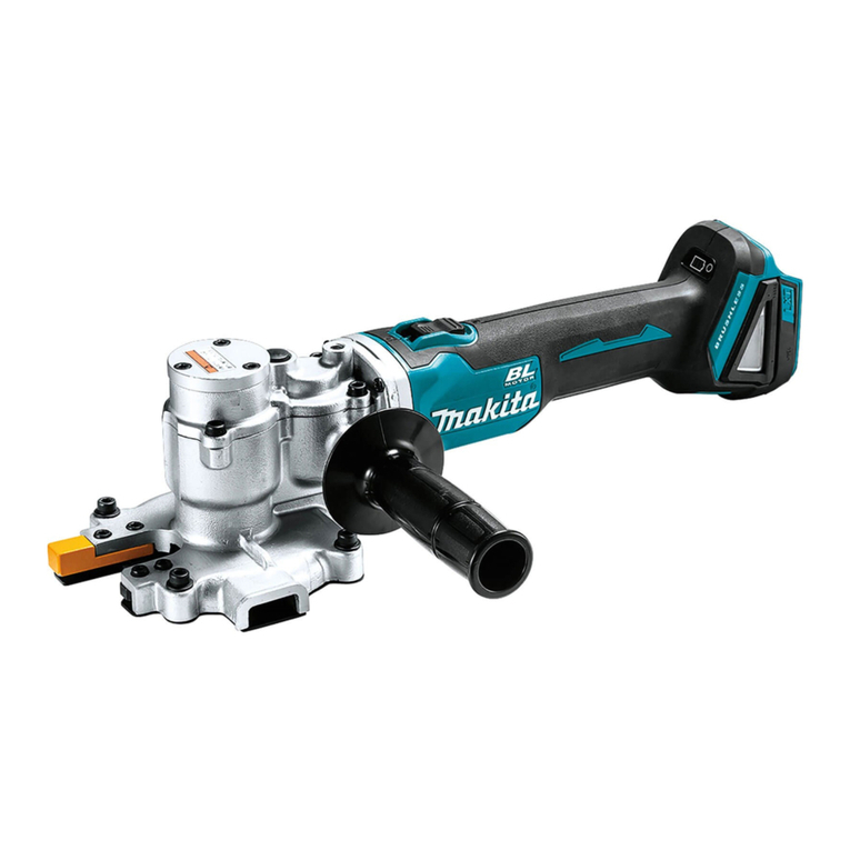
Makita DCE090 User manual

DCE090
EN Cordless Power Cutter INSTRUCTION MANUAL 7
PL Przecinarka Akumulatorowa INSTRUKCJA OBSŁUGI 16
HU Akkumulátoros
vágószerszám HASZNÁLATI KÉZIKÖNYV 26
SK Akumulátorová motorová
rezačka NÁVOD NA OBSLUHU 35
CS Akumulátorová elektrická
řezačka NÁVOD K OBSLUZE 44
UK Акумуляторний різак ІНСТРУКЦІЯ З
ЕКСПЛУАТАЦІЇ 53
RO Mașină de tăiat electrică cu
acumulator MANUAL DE INSTRUCŢIUNI 63
DE Akku-Trennschleifer BETRIEBSANLEITUNG 72

18
1
2
3 4
98
6
5
7
10
11
12
14 15
17
13
16
19
20
Fig.1
1
2
Fig.2
1
23
Fig.3
2

1
2
Fig.4
12
Fig.5
1
Fig.6
1
2
Fig.7
1
2
Fig.8
1
2
3
4
Fig.9
123
4
55
Fig.10
3

1
23
4
5
Fig.11
1
2
3
Fig.12
12
3
Fig.13
1
2
3
Fig.14
Fig.15
1
Fig.16
Fig.17
1
Fig.18
4

Fig.19
12
Fig.20
1
2
Fig.21
1
2
Fig.22
5

1
2
3
Fig.23
1
2
3
Fig.24
1
2
1
2
Fig.25
1
3
2
Fig.26
6

7ENGLISH
ENGLISH (Original instructions)
SPECIFICATIONS
Model: DCE090
Wheel diameter 230 mm
Max. wheel thickness 3.0 mm
Max.cutting depth 88 mm
Rated speed 6,600 min-1
Rated voltage D.C. 36 V
Max. permitted pressure of feed-water 5.0 bars
Overall length 554 mm
Net weight 5.6 - 6.3 kg
• Duetoourcontinuingprogramofresearchanddevelopment,thespecicationshereinaresubjecttochange
without notice.
• Specicationsmaydierfromcountrytocountry.
• Theweightmaydierdependingontheattachment(s),includingthebatterycartridge.Thelightestandheavi-
est combination, according to EPTA-Procedure 01/2014, are shown in the table.
Applicable battery cartridge and charger
Batterycartridge BL1815N / BL1820 / BL1820B / BL1830 / BL1830B / BL1840 /
BL1840B / BL1850 / BL1850B / BL1860B
Charger DC18RC / DC18RD / DC18RE / DC18SD / DC18SE / DC18SF /
DC18SH
•
Someofthebatterycartridgesandchargerslistedabovemaynotbeavailabledependingonyourregionofresidence.
WARNING: Only use the battery cartridges and chargers listed above.Useofanyotherbatterycartridges
andchargersmaycauseinjuryand/orre.
Intended use
The tool is intended for cutting in metal materials with a
abrasivecut-owheelandalsomasonrymaterialswith
a diamond wheel.
Noise
ThetypicalA-weightednoiseleveldeterminedaccordingtoEN60745-2-22:
Soundpressurelevel(LpA):103dB(A)
Soundpowerlevel(LWA):114dB(A)
Uncertainty(K):3dB(A)
NOTE:Thedeclarednoiseemissionvalue(s)hasbeenmeasuredinaccordancewithastandardtestmethodand
maybeusedforcomparingonetoolwithanother.
NOTE:Thedeclarednoiseemissionvalue(s)mayalsobeusedinapreliminaryassessmentofexposure.
WARNING: Wear ear protection.
WARNING: The noise emission during actual use of the power tool can dier from the declared val-
ue(s) depending on the ways in which the tool is used especially what kind of workpiece is processed.
WARNING: Be sure to identify safety measures to protect the operator that are based on an estimation
of exposure in the actual conditions of use (taking account of all parts of the operating cycle such as the
times when the tool is switched o and when it is running idle in addition to the trigger time).

8ENGLISH
Vibration
Workmode:concretecutting
Left hand Right hand Applicable standard
ah,W (m/s2)Uncertainty K
(m/s2)
ah,W (m/s2)Uncertainty K
(m/s2)
5.9 1.5 4.0 1.5 EN60745-2-22
NOTE:Thedeclaredvibrationtotalvalue(s)hasbeenmeasuredinaccordancewithastandardtestmethodand
maybeusedforcomparingonetoolwithanother.
NOTE:Thedeclaredvibrationtotalvalue(s)mayalsobeusedinapreliminaryassessmentofexposure.
WARNING: The vibration emission during actual use of the power tool can dier from the declared
value(s) depending on the ways in which the tool is used especially what kind of workpiece is processed.
WARNING: Be sure to identify safety measures to protect the operator that are based on an estimation
of exposure in the actual conditions of use (taking account of all parts of the operating cycle such as the
times when the tool is switched o and when it is running idle in addition to the trigger time).
EC Declaration of Conformity
For European countries only
TheECdeclarationofconformityisincludedasAnnexA
to this instruction manual.
SAFETY WARNINGS
General power tool safety warnings
WARNING:
Read all safety warnings, instruc-
tions, illustrations and specications provided with this
power tool. Failure to follow all instructions listed below
mayresultinelectricshock,reand/orseriousinjury.
Save all warnings and instruc-
tions for future reference.
Theterm"powertool"inthewarningsreferstoyour
mains-operated(corded)powertoolorbattery-operated
(cordless)powertool.
Cordless cutter safety warnings
1.
The guard provided with the tool must be securely
attached to the power tool and positioned for
maximum safety, so the least amount of wheel is
exposed towards the operator. Position yourself
and bystanders away from the plane of the rotating
wheel. The guard helps to protect operator from broken
wheel fragments and accidental contact with wheel.
2.
Use only bonded reinforced or diamond cut-o wheels for
your power tool.Justbecauseanaccessorycanbeattached
toyourpowertool,itdoesnotassuresafeoperation.
3. The rated speed of the accessory must be at
least equal to the maximum speed marked on
the power tool. Accessories running faster than
theirratedspeedcanbreakandyapart.
4.
Wheels must be used only for recommended
applications. For example: do not grind with the
side of cut-o wheel.Abrasivecut-owheelsare
intended for peripheral grinding, side forces applied
tothesewheelsmaycausethemtoshatter.
5. Always use undamaged wheel anges that are
of correct diameter for your selected wheel.
Properwheelangessupportthewheelthus
reducingthepossibilityofwheelbreakage.
6. Do not use worn down reinforced wheels from
larger power tools. Wheels intended for a larger
power tool are not suitable for the higher speed of
asmallertoolandmayburst.
7. The outside diameter and the thickness of your
accessory must be within the capacity rating
of your power tool.Incorrectlysizedaccessories
cannotbeadequatelyguardedorcontrolled.
8. The arbour size of wheels and anges must
properly t the spindle of the power tool.
Wheelsandangeswitharbourholesthatdonot
match the mounting hardware of the power tool
willrunoutofbalance,vibrateexcessivelyand
maycauselossofcontrol.
9. Do not use damaged wheels. Before each
use, inspect the wheels for chips and cracks.
If power tool or wheel is dropped, inspect for
damage or install an undamaged wheel. After
inspecting and installing the wheel, position
yourself and bystanders away from the plane
of the rotating wheel and run the power tool
at maximum no load speed for one minute.
Damagedwheelswillnormallybreakapartduring
this test time.
10. Wear personal protective equipment.
Depending on application, use face shield,
safety goggles or safety glasses. As appro-
priate, wear dust mask, hearing protectors,
gloves and shop apron capable of stopping
small abrasive or workpiece fragments. The
eyeprotectionmustbecapableofstoppingying
debrisgeneratedbyvariousoperations.Thedust
maskorrespiratormustbecapableofltrating
particlesgeneratedbyyouroperation.Prolonged
exposuretohighintensitynoisemaycausehear-
ing loss.
11. Keep bystanders a safe distance away from
work area. Anyone entering the work area
must wear personal protective equipment.
Fragmentsofworkpieceorofabrokenwheelmay
yawayandcauseinjurybeyondimmediatearea
of operation.

9ENGLISH
12.
Hold the power tool by insulated gripping sur-
faces only, when performing an operation where
the cutting accessory may contact hidden wir-
ing.Cuttingaccessorycontactinga“live”wiremay
makeexposedmetalpartsofthepowertool“live”
and could give the operator an electric shock.
13. Never lay the power tool down until the acces-
sory has come to a complete stop. The spinning
wheelmaygrabthesurfaceandpullthepower
tooloutofyourcontrol.
14. Do not run the power tool while carrying it at
your side. Accidental contact with the spinning
accessorycouldsnagyourclothing,pullingthe
accessoryintoyourbody.
15. Regularly clean the power tool’s air vents. The
motor’s fan will draw the dust inside the housing
and excessive accumulation of powdered metal
maycauseelectricalhazards.
16. Do not operate the power tool near ammable
materials. Sparks could ignite these materials.
Kickback and related warnings
Kickbackisasuddenreactiontoapinchedorsnagged
rotating wheel. Pinching or snagging causes rapid stall-
ing of the rotating wheel which in turn causes the uncon-
trolled power tool to be forced in the direction opposite of
the wheel’s rotation at the point of the binding.
For example, if an abrasive wheel is snagged or
pinchedbytheworkpiece,theedgeofthewheelthatis
entering into the pinch point can dig into the surface of
the material causing the wheel to climb out or kick out.
Thewheelmayeitherjumptowardorawayfromthe
operator, depending on direction of the wheel’s move-
mentatthepointofpinching.Abrasivewheelsmayalso
break under these conditions.
Kickbackistheresultofpowertoolmisuseand/or
incorrect operating procedures or conditions and can be
avoidedbytakingproperprecautionsasgivenbelow.
1. Maintain a rm grip on the power tool and
position your body and arm to allow you to
resist kickback forces. Always use auxiliary
handle, if provided, for maximum control over
kickback or torque reaction during start-up.
The operator can control torque reactions or kick-
back forces, if proper precautions are taken.
2. Never place your hand near the rotating acces-
sory.Accessorymaykickbackoveryourhand.
3. Do not position your body in line with the
rotating wheel.Kickbackwillpropelthetoolin
direction opposite to the wheel’s movement at the
point of snagging.
4. Use special care when working corners, sharp
edges etc. Avoid bouncing and snagging the
accessory. Corners, sharp edges or bouncing
haveatendencytosnagtherotatingaccessory
and cause loss of control or kickback.
5.
Do not attach a saw chain, woodcarving blade,
segmented diamond wheel with a peripheral gap
greater than 10 mm or toothed saw blade. Such
blades create frequent kickback and loss of control.
6. Do not “jam” the wheel or apply excessive
pressure. Do not attempt to make an excessive
depth of cut. Overstressing the wheel increases
theloadingandsusceptibilitytotwistingorbinding
ofthewheelinthecutandthepossibilityofkick-
back or wheel breakage.
7. When wheel is binding or when interrupting
a cut for any reason, switch o the power
tool and hold the power tool motionless until
the wheel comes to a complete stop. Never
attempt to remove the wheel from the cut while
the wheel is in motion otherwise kickback may
occur. Investigate and take corrective action to
eliminate the cause of wheel binding.
8. Do not restart the cutting operation in the
workpiece. Let the wheel reach full speed and
carefully re-enter the cut.Thewheelmaybind,
walk up or kickback if the power tool is restarted in
the workpiece.
9. Support panels or any oversized workpiece to
minimize the risk of wheel pinching and kick-
back. Large workpieces tend to sag under their
own weight. Supports must be placed under the
workpiece near the line of cut and near the edge
of the workpiece on both sides of the wheel.
10. Use extra caution when making a “pocket cut”
into existing walls or other blind areas. The
protrudingwheelmaycutgasorwaterpipes,elec-
tricalwiringorobjectsthatcancausekickback.
Additional Safety Warnings:
1. Before using a segmented diamond wheel,
make sure that the diamond wheel has the
peripheral gap between segments of 10 mm or
less, only with a negative rake angle.
2. Never attempt to cut with the tool held upside
down in a vise. This can lead to serious acci-
dents, because it is extremely dangerous.
3. Some material contains chemicals which may
be toxic. Take caution to prevent dust inhala-
tion and skin contact. Follow material supplier
safety data.
4. Store wheels as per manufacturer recommen-
dations. Improper storage may damage the
wheels.
5. Always use the wheel suitable for your work
and the material to be cut.
6. Examine the material to be cut before cutting.
Ifthematerialcontainsexplosiveorammable
substances,itmaycauseanexplosionorre.
7. Do not switch on the tool if a foreign object
is jammed between the guard and the wheel.
Inthiscase,uninstallthebatterycartridgeand
removetheforeignobject.
8. Use clamps or similar to support the work-
piece whenever possible.
9. Always wear hearing protection during
operation.
10. Do not cut wood materials with this tool.
SAVE THESE INSTRUCTIONS.
WARNING: DO NOT let comfort or familiarity
with product (gained from repeated use) replace
strict adherence to safety rules for the subject
product. MISUSE or failure to follow the safety
rules stated in this instruction manual may cause
serious personal injury.
10 ENGLISH
Important safety instructions for
battery cartridge
1.
Before using battery cartridge, read all instruc-
tions and cautionary markings on (1) battery char-
ger, (2) battery, and (3) product using battery.
2. Do not disassemble or tamper the battery
cartridge.Itmayresultinare,excessiveheat,
or explosion.
3. If operating time has become excessively
shorter, stop operating immediately. It may
result in a risk of overheating, possible burns
and even an explosion.
4.
If electrolyte gets into your eyes, rinse them out
with clear water and seek medical attention right
away. It may result in loss of your eyesight.
5. Do not short the battery cartridge:
(1) Do not touch the terminals with any con-
ductive material.
(2) Avoid storing battery cartridge in a con-
tainer with other metal objects such as
nails, coins, etc.
(3) Do not expose battery cartridge to water
or rain.
A battery short can cause a large current
ow, overheating, possible burns and even a
breakdown.
6. Do not store and use the tool and battery car-
tridge in locations where the temperature may
reach or exceed 50 °C (122 °F).
7. Do not incinerate the battery cartridge even if
it is severely damaged or is completely worn
out. The battery cartridge can explode in a re.
8. Do not nail, cut, crush, throw, drop the battery
cartridge, or hit against a hard object to the
battery cartridge.Suchconductmayresultina
re,excessiveheat,orexplosion.
9. Do not use a damaged battery.
10.
The contained lithium-ion batteries are subject to
the Dangerous Goods Legislation requirements.
Forcommercialtransportse.g.bythirdparties,
forwarding agents, special requirement on pack-
aging and labeling must be observed.
For preparation of the item being shipped, consult-
inganexpertforhazardousmaterialisrequired.
Pleasealsoobservepossiblymoredetailed
national regulations.
Tapeormaskoopencontactsandpackupthe
batteryinsuchamannerthatitcannotmove
around in the packaging.
11. When disposing the battery cartridge, remove
it from the tool and dispose of it in a safe
place. Follow your local regulations relating to
disposal of battery.
12. Use the batteries only with the products
specied by Makita. Installing the batteries to
non-compliantproductsmayresultinare,exces-
siveheat,explosion,orleakofelectrolyte.
13. If the tool is not used for a long period of time,
the battery must be removed from the tool.
14. During and after use, the battery cartridge may
take on heat which can cause burns or low
temperature burns. Pay attention to the han-
dling of hot battery cartridges.
15.
Do not touch the terminal of the tool immediately
after use as it may get hot enough to cause burns.
16. Do not allow chips, dust, or soil stuck into the
terminals, holes, and grooves of the battery
cartridge.Itmayresultinpoorperformanceor
breakdownofthetoolorbatterycartridge.
17. Unless the tool supports the use near
high-voltage electrical power lines, do not use
the battery cartridge near high-voltage electri-
cal power lines.Itmayresultinamalfunctionor
breakdownofthetoolorbatterycartridge.
18. Keep the battery away from children.
SAVE THESE INSTRUCTIONS.
CAUTION:
Only use genuine Makita batteries.
Use of non-genuine Makita batteries, or batteries that
havebeenaltered,mayresultinthebatterybursting
causingres,personalinjuryanddamage.Itwillalso
voidtheMakitawarrantyfortheMakitatoolandcharger.
Tips for maintaining maximum
battery life
1. Charge the battery cartridge before completely
discharged. Always stop tool operation and
charge the battery cartridge when you notice
less tool power.
2.
Never recharge a fully charged battery cartridge.
Overcharging shortens the battery service life.
3.
Charge the battery cartridge with room tempera-
ture at 10 °C - 40 °C (50 °F - 104 °F). Let a hot
battery cartridge cool down before charging it.
4. When not using the battery cartridge, remove
it from the tool or the charger.
5. Charge the battery cartridge if you do not use
it for a long period (more than six months).
PARTS DESCRIPTION
►Fig.1
1Abrasivecut-owheel/
diamond wheel
2Wheel guard 3Grip 4Cover(forbattery
compartment)
5Lock-obutton 6Hook 7Lamp 8Check button
9Batteryindicator 10 Overload indicator 11 Lamp button 12 Switch trigger
13 Handle 14 Water inlet 15 Cock 16 Cover(forV-belt)
17 Shaft lock button 18 Coupling sleeve 19 Box wrench 20 Hex wrench

11 ENGLISH
FUNCTIONAL
DESCRIPTION
CAUTION: Always be sure that the tool is
switched o and the battery cartridge is removed
before adjusting or checking function on the tool.
Installing or removing battery
cartridge
CAUTION: Always switch o the tool before
installing or removing of the battery cartridge.
CAUTION: Hold the tool and the battery car-
tridge rmly when installing or removing battery
cartridge.Failuretoholdthetoolandthebattery
cartridgermlymaycausethemtoslipoyourhands
andresultindamagetothetoolandbatterycartridge
andapersonalinjury.
Toinstallthebatterycartridge,openthecoverwhile
releasingthehook.Alignthetongueonthebattery
cartridge with the groove in the housing and slip it into
place.Insertitallthewayuntilitlocksinplacewitha
littleclick.Ifyoucanseetheredindicatorontheupper
sideofthebutton,itisnotlockedcompletely.
Afterinstallingorremovingthebatterycartridges,make
surethatthecoverisclosedandlockedbythehook.
►Fig.2: 1. Cover 2. Hook
Toremovethebatterycartridges,liftthebatterycar-
tridge while pushing the button on the front of the
cartridge.
►Fig.3: 1. Red indicator 2. Button 3.Batterycartridge
CAUTION: Always install the battery cartridge
fully until the red indicator cannot be seen. If not,
itmayaccidentallyfalloutofthetool,causinginjuryto
youorsomeonearoundyou.
CAUTION: Do not install the battery cartridge
forcibly.Ifthecartridgedoesnotslideineasily,itis
notbeinginsertedcorrectly.
NOTE:Thetooldoesnotworkwithonlyonebattery
cartridge.
Indicating the remaining battery
capacity
Only for battery cartridges with the indicator
►Fig.4: 1. Indicator lamps 2. Check button
Pressthecheckbuttononthebatterycartridgetoindi-
catetheremainingbatterycapacity.Theindicatorlamps
light up for a few seconds.
Indicator lamps Remaining
capacity
Lighted O Blinking
75%to100%
50%to75%
25%to50%
0%to25%
Charge the
battery.
Thebattery
mayhave
malfunctioned.
NOTE: Depending on the conditions of use and the
ambienttemperature,theindicationmaydierslightly
fromtheactualcapacity.
NOTE:Therst(farleft)indicatorlampwillblinkwhen
thebatteryprotectionsystemworks.
Indicating the remaining battery
capacity
►Fig.5: 1.Batteryindicator2. Check button
Pressthecheckbuttontoindicatetheremainingbattery
capacities.Thebatteryindicatorscorrespondtoeach
battery.
Battery indicator status Remaining
battery
capacity
On O Blinking
50%to100%
20%to50%
0%to20%
Charge the
battery

12 ENGLISH
Tool / battery protection system
Thetoolisequippedwithatool/batteryprotectionsystem.This
systemautomaticallycutsopowertothemotortoextendtooland
batterylife.Thetoolwillautomaticallystopduringoperationifthe
toolorbatteryisplacedunderoneofthefollowingconditions.
Overload protection
Whenthetool/batteryisoperatedinamannerthatcausesitto
drawanabnormallyhighcurrent,thetoolautomaticallystops.In
thissituation,turnthetooloandstoptheapplicationthatcaused
the tool to become overloaded. Then turn the tool on to restart.
Overheat protection
Whenthetoolisoverheated,thetoolstopsautomatically,and
thebatteryindicatorblinkabout60seconds.Inthissituation,
let the tool cool down before turning the tool on again.
On Blinking
Overdischarge protection
Whenthebatterycapacitybecomeslow,thetoolstops
automatically.Iftheproductdoesnotoperateeven
when the switches are operated, remove the batteries
from the tool and charge the batteries.
Overload alert
If the tool is operated with excessive load, the overload
indicator will blink in red. In this situation, reduce the
load on the tool. Then, the indicator stops blinking.
►Fig.6: 1. Overload indicator
Switch action
WARNING: Before installing the battery car-
tridge into the tool, always check to see that the
switch trigger actuates properly and returns to
the "OFF" position when released.
WARNING: NEVER defeat the lock-o button
by taping down or some other means. A switch with
anegatedlock-obuttonmayresultinunintentional
operationandseriouspersonalinjury.
WARNING: NEVER use the tool if it runs when
you simply pull the switch trigger without press-
ing the lock-o button. A switch in need of repair
mayresultinunintentionaloperationandserious
personalinjury.ReturntooltoaMakitaservicecenter
for proper repairs BEFORE further usage.
Topreventtheswitchtriggerfrombeingaccidentally
pulled,alock-obuttonisprovided.Tostartthetool,
depressthelock-obuttonandpulltheswitchtrigger.
Release the switch trigger to stop.
►Fig.7: 1. Switch trigger 2.Lock-obutton
NOTICE: Do not pull the switch trigger hard
without pressing in the lock-o button. This can
cause switch breakage.
Lighting the lamp
CAUTION: Do not look in the light or see the
source of light directly.
Toturnonthelamp,pressthelampbutton.Toturno,
press the lamp button again.
►Fig.8: 1. Lamp button 2. Lamp
NOTE:Thelampwillautomaticallybeturnedoif
there is no operation with the tool for one minute.
ASSEMBLY
CAUTION: Always be sure that the tool is
switched o and the battery cartridge is removed
before carrying out any work on the tool.
Installing or removing abrasive cut-
o wheel / diamond wheel
CAUTION: Use only the Makita wrench to
install or remove the wheel.
CAUTION: When installing the wheel, be sure
to tighten the bolt securely.
CAUTION: Do not press the shaft lock button
when the wheel is rotating.
To remove the wheel, press the shaft lock button and
rotate the wheel until the wheel cannot revolve. While
theshaftlockisfullylocked,turnthehexboltcounter-
clockwise using the box wrench. Then remove the hex
bolt,outerangeandwheel.
►Fig.9: 1. Shaft lock button 2. Box wrench 3. Tighten
4. Loosen
►Fig.10: 1. Hex bolt 2.Outerange(black)
3.Abrasivecut-owheel/diamondwheel
4.Innerange(silver)5.Arrow(rotation
directionofthewheel)
To install the wheel, follow the removal procedure in
reverse.
BE SURE TO TIGHTEN THE HEX BOLT SECURELY.
CAUTION: Always install the wheel so that
the arrow on it points in the same direction as
the arrow on the wheel guard. Otherwise the wheel
rotatesinreverse,itmaycausepersonalinjury.
CAUTION: Only use the wheel that are
marked with a speed equal or higher than the
speed marked on the tool.
NOTE:Ifaninnerangeisremovedbychance,
installtheinnerangesothattallerprotrusionfaces
thetoolsideasshowninthegure.
►Fig.11: 1. Hex bolt 2.Outerange(black)
3.Abrasivecut-owheel/diamondwheel
4.Innerange(silver)5.Protrusion(taller)

13 ENGLISH
Connecting to water supply
1. Prepare a water hose.
2. Remove the nut on the coupling sleeve and pass
the water hose through the nut. Insert the end of the
hose into the coupling sleeve and then tighten the nut.
►Fig.12: 1. Water hose 2. Nut of the coupling sleeve
3. Coupling sleeve
3. Connectthewaterhosetothewatersupply.
Whenconnectingtoawaterfaucet,useasuitabletting
suchashosebandorwatertapjoint.
►Fig.13: 1. Hose band 2.Watertapjoint3. Water
hose
NOTE:Thettingdependsontheshapeofthefaucet
towhichyouconnect.Prepareasuitablecommercial-
ly-boughttting.
NOTE:Ifyouuseawatertapjoint,prepareanother
coupling sleeve and attach it to the other end of the
hose.
NOTE: When using a water pump, follow the instruc-
tionsofyourwaterpumptoconnectthewaterhose.
4. Push the coupling sleeve into the water inlet until it
locks with a click.
►Fig.14: 1. Coupling sleeve 2. Water inlet 3. Cock
NOTICE: Keep the cock closed until you start the
cutting operation with water feeding. For how to
feed water, refer to the section for the operation.
OPERATION
CAUTION: Be sure to lock the cover for bat-
tery compartment before operating.
CAUTION: Be sure to hold the workpiece
rmly down on a stable bench or table during
operation.
CAUTION: Do not twist or force the tool in the
cut, or the motor may be overloaded or the work-
piece may break.
Cutting
CAUTION: During operation, do not bring the
tool higher than your shoulder height.
►Fig.15
Holdthetoolrmly.Graspthehandlewithyourright
handandthegripwithyourlefthand.Topreventelectric
shockbyaccidentalcuttingofanelectriccable,always
holdthegripbythedesignatedportionasshowninthe
gure.
►Fig.16: 1. Part to hold
Move the tool over the workpiece surface, keeping it
atandadvancingsmoothlyuntilthecuttingiscom-
pleted.Keepyourcuttinglinestraightandyourspeedof
advance uniform.
►Fig.17
NOTE:Whenthebatterycartridgetemperatureis
low,thetoolmaynotworktoitsfullcapacity.Atthis
time,forexample,usethetoolforalight-dutycutfor
awhileuntilthebatterycartridgewarmsupashigh
as room temperature. Then, the tool can work to its
fullcapacity.
NOTE: If the cutting action of the diamond wheel
begins to diminish, dress the cutting edge of the
wheel using an old discarded coarse grit bench
grinderwheelorconcreteblock.Dressbypressing
lightlyontheouteredgeofthediamondwheel.
When feeding water during cutting
CAUTION: When using a wet-type diamond
wheel, always feed water during cutting.
Connectthetooltothewatersupplyandturnthecock
inthedirectionofthearrowasillustrated.Adjustthe
positionofthecocktoobtainagentleowofwater.
►Fig.18: 1. Cock
CAUTION: When feeding water, always keep
the tool head lower than the tool body to prevent
water entering into the tool mechanism. Failure to
dosomaycauseelectricshock.
►Fig.19
MAINTENANCE
CAUTION: Always be sure that the tool is
switched o and the battery cartridge is removed
before attempting to perform inspection or
maintenance.
NOTICE: Never use gasoline, benzine, thinner,
alcohol or the like. Discoloration, deformation or
cracks may result.
To maintain product SAFETY and RELIABILITY,
repairs,anyothermaintenanceoradjustmentshould
beperformedbyMakitaAuthorizedorFactoryService
Centers,alwaysusingMakitareplacementparts.
Cleaning the tool
Aftereachuse,removethebatterycartridgeandthe
wheel and then clean dust, dirt or metal chips accu-
mulatedinsidethewheelguard.Cleanthetoolbody
bywipingodust,dirtwithadryclothoronedippedin
soapywaterandwrungout.Useadryclothtowipethe
dirtothelensofthelamp.Becarefulnottoscratchthe
lensoflamp,oritmaylowertheillumination.
►Fig.20: 1. Wheel guard 2. Lens of the lamp
Cleaning the air vent
Regularlycleanthetool'sairventsorwheneverthe
vents start to become obstructed.
►Fig.21: 1. Inhalation vent 2. Exhaust vent

14 ENGLISH
Changing the V-belt
1. Removethebatterycartridgeandthewheel.
2. Loosen the hex socket bolts using the hex wrench
and then remove the cover .
►Fig.22: 1. Hex socket bolt 2. Cover
3. WhilestronglytwistingtheV-beltsothatitsinner
sidefacesupasshowninthegure,turntheboltonthe
pulley(large)clockwiseusingtheboxwrench.
TheV-beltwilldeviatefromthetrackandcomeoas
youturnthebolt.
►Fig.23: 1. V-belt 2.Pulley(large)3. Box wrench
NOTICE: Never turn the box wrench counter-
clockwise. Doing so loosen the bolt on the pulley
(large) and result in poor performance.
4. HookthenewV-belttothepulley(small).Putthe
otherendoftheV-beltontothepulley(large)sothat
itispartiallyhookedontheforefrontrailofthepulley.
(Youdon'thavetohooktheV-belttoalloftherailson
thepulleyatthisstage).Afterthat,turntheboltonthe
pulley(large)clockwiseusingtheboxwrench.
TheV-beltwillgetonthetrackasyouturnthebolt.
►Fig.24:
1.Pulley(small)2.Pulley(large)3. Box wrench
Make sure that all the guides on the internal circle of the
V-belttintotherailsonthepulleys.Alltherailsonthe
pulleymustsupporttheguidesontheV-belt.Ifthereis
a rail which does not support the guide, the V-belt is not
properlyinstalled.
►Fig.25: 1.Railonthepulley2. Guide on the V-belt
5. Place the cover onto the tool and tighten the hex
socket bolts using the hex wrench.
►Fig.26: 1. Tube 2. Cover 3. Hex socket bolt
NOTICE: Make sure that the tube for water feed
is in the positions as shown in the gure before
attaching the cover.
TROUBLESHOOTING
Beforeaskingforrepairs,conductyourowninspectionrst.Ifyoundaproblemthatisnotexplainedinthemanual,
donotattempttodismantlethetool.Instead,askMakitaAuthorizedServiceCenters,alwaysusingMakitareplace-
ment parts for repairs.
State of abnormality Probable cause (malfunction) Remedy
Motor does not run. Batterycartridgesarenotinstalled. Installtwobatterycartridges.Thistooldoesnot
workwithonebatterycartridge.
Batteryproblem(undervoltage) Rechargethebattery.Ifrechargingisnoteective,
replacethebatterycartridge.
Thedrivesystemdoesnotwork
correctly. Askyourlocalauthorizedservicecenterforrepair.
Motor stops running after a little use. Battery'schargelevelislow. Rechargethebattery.Ifrechargingisnoteective,
replacethebatterycartridge.
Overheating. Stop using of tool to allow it to cool down.
The wheel rotation does not acceler-
ateproperlyevenafterrunningthe
tool without load for 20 seconds.
Batteryisinstalledimproperly. Installthebatterycartridgeasdescribedinthis
manual.
Batterypowerisdropping. Rechargethebatterycartridge.Ifrechargingisnot
eective,replacethebatterycartridge.
The V-belt is slipping. Replace the V-belt with new one.
Thedrivesystemdoesnotwork
correctly. Askyourlocalauthorizedservicecenterforrepair.
Wheeldoesnotrotate:
stopthemachineimmediately!
The V-belt is slipping. Replace the V-belt with new one.
Foreignobjectisjammedbetweenthe
guard and the wheel. Uninstallthebatterycartridgeandthenremovethe
foreignobject.
Thedrivesystemdoesnotwork
correctly. Askyourlocalauthorizedservicecenterforrepair.
Abnormalvibration:
stopthemachineimmediately!
Improper attachment of the wheel. Install the wheel as instructed in this manual.
Tightenthebolttosecurethewheelrmly.
Thedrivesystemdoesnotwork
correctly. Askyourlocalauthorizedservicecenterforrepair.
Cuttingtoolandmotorcannotstop:
Removethebatterycartridge
immediately!
Electric or electronic malfunction. Removethebatterycartridgeandaskyourlocal
authorizedservicecenterforrepair.
Poor cutting performance It is time to replace the wheel. Replace the wheel with new one.
Water leaks from the inlet. Water is leaking from the O-ring part. Askyourlocalauthorizedservicecenterforrepair.

15 ENGLISH
OPTIONAL
ACCESSORIES
CAUTION: These accessories or attachments
are recommended for use with your Makita tool
specied in this manual.Theuseofanyother
accessories or attachments might present a risk of
injurytopersons.Onlyuseaccessoryorattachment
for its stated purpose.
Ifyouneedanyassistanceformoredetailsregard-
ingtheseaccessories,askyourlocalMakitaService
Center.
• Abrasivecut-owheel
• Diamond wheel
• V-belt
• Coupling sleeve
• Flange60set(countryspecic)
• Box wrench
• Hex wrench
• Makitagenuinebatteryandcharger
NOTE:Someitemsinthelistmaybeincludedinthe
toolpackageasstandardaccessories.Theymay
dierfromcountrytocountry.

16 POLSKI
POLSKI (Instrukcja oryginalna)
DANE TECHNICZNE
Model: DCE090
Średnicatarczy/ściernicy 230 mm
Maks.grubośćtarczy/ściernicy 3,0 mm
Maks.głębokośćcięcia 88 mm
Prędkośćznamionowa 6 600 min-1
Napięcieznamionowe Prądstały36V
Maks.dopuszczalneciśnieniedoprowadzanejwody 5,0 bar
Długośćcałkowita 554 mm
Masa netto 5,6 - 6,3 kg
• Wzwiązkuzestaleprowadzonymprzeznasząrmęprogramembadawczo-rozwojowymniniejszedanemogą
uleczmianombezwcześniejszegopowiadomienia.
• Danetechnicznemogąróżnićsięwzależnościodkraju.
• Masamożebyćróżnawzależnościodosprzętu,wtymakumulatora.Wtabeliprzedstawionajestnajlżejszai
najcięższakonguracja,zgodniezprocedurąEPTA01/2014.
Kompatybilne akumulatory i ładowarki
Akumulator BL1815N / BL1820 / BL1820B / BL1830 / BL1830B / BL1840 /
BL1840B / BL1850 / BL1850B / BL1860B
Ładowarka DC18RC / DC18RD / DC18RE / DC18SD / DC18SE / DC18SF /
DC18SH
•
Pewnezwymienionychpowyżejakumulatorówiładowarekmogąbyćniedostępnewregioniezamieszkaniaużytkownika.
OSTRZEŻENIE: Należy używać wyłącznie akumulatorów i ładowarek wymienionych powyżej.
Używanieinnychakumulatorówiładowarekmożestwarzaćryzykowystąpieniaobrażeńciałalubpożaru.
Przeznaczenie
Narzędziejestprzeznaczonedocięciametalowych
materiałówzapomocąściernicytnącejorazmateriałów
budowlanychzapomocątarczydiamentowej.
Hałas
TypowyrównoważnypoziomdźwiękuAokreślonywoparciuonormęEN60745-2-22:
Poziomciśnieniaakustycznego(LpA):103dB(A)
Poziommocyakustycznej(LWA):114dB(A)
Niepewność(K):3dB(A)
WSKAZÓWKA:Deklarowanawartośćemisjihałasuzostałazmierzonazgodniezestandardowąmetodątestowąi
możnająwykorzystaćdoporównywanianarzędzi.
WSKAZÓWKA:Deklarowanąwartośćemisjihałasumożnatakżewykorzystaćwewstępnejocenienarażenia.
OSTRZEŻENIE: Nosić ochronniki słuchu.
OSTRZEŻENIE:
Poziom hałasu wytwarzanego podczas rzeczywistego użytkowania elektronarzędzia może się różnić od
wartości deklarowanej w zależności od sposobu użytkowania narzędzia, a w szczególności od rodzaju obrabianego elementu.
OSTRZEŻENIE:
W oparciu o szacowane narażenie w rzeczywistych warunkach użytkowania należy okre-
ślić środki bezpieczeństwa w celu zapewnienia ochrony operatora (uwzględniając wszystkie elementy cyklu dzia-
łania, tj. czas, kiedy narzędzie jest wyłączone i kiedy pracuje na biegu jałowym, a także czas, kiedy jest włączone).

17 POLSKI
Drgania
Trybpracy:cięciebetonu
Lewa ręka Prawa ręka Obowiązująca norma
ah,W (m/s2)
Niepewność K
(m/s2)
ah,W (m/s2)
Niepewność K
(m/s2)
5,9 1,5 4,0 1,5 EN60745-2-22
WSKAZÓWKA:Deklarowanawartośćpoziomudrgańzostałazmierzonazgodniezestandardowąmetodą
testowąimożnająwykorzystaćdoporównywanianarzędzi.
WSKAZÓWKA:Deklarowanąwartośćpoziomudrgańmożnatakżewykorzystaćwewstępnejocenienarażenia.
OSTRZEŻENIE: Drgania wytwarzane podczas rzeczywistego użytkowania elektronarzędzia mogą się
różnić od wartości deklarowanej w zależności od sposobu użytkowania narzędzia, a w szczególności od
rodzaju obrabianego elementu.
OSTRZEŻENIE: W oparciu o szacowane narażenie w rzeczywistych warunkach użytkowania należy
określić środki bezpieczeństwa w celu zapewnienia ochrony operatora (uwzględniając wszystkie elementy
cyklu działania, tj. czas, kiedy narzędzie jest wyłączone i kiedy pracuje na biegu jałowym, a także czas,
kiedy jest włączone).
Deklaracja zgodności WE
Dotyczy tylko krajów europejskich
DeklaracjazgodnościWEjestdołączonajakozałącznik
Adoniniejszejinstrukcjiobsługi.
OSTRZEŻENIA
DOTYCZĄCE
BEZPIECZEŃSTWA
Ogólne zasady bezpiecznej
eksploatacji elektronarzędzi
OSTRZEŻENIE: Należy zapoznać się z
ostrzeżeniami dotyczącymi bezpieczeństwa,
instrukcjami, ilustracjami i danymi technicz-
nymi dołączonymi do tego elektronarzędzia.
Niezastosowaniesiędopodanychponiżejinstrukcji
możeprowadzićdoporażeniaprądem,pożarui/lub
poważnychobrażeńciała.
Wszystkie ostrzeżenia i instruk-
cje należy zachować do wykorzy-
stania w przyszłości.
Pojęcie„elektronarzędzie",występującewwymienio-
nychtuostrzeżeniach,odnosisiędoelektronarzędzia
zasilanegozsiecielektrycznej(zprzewodemzasilają-
cym)lubdoelektronarzędziaakumulatorowego(bez
przewoduzasilającego).
Ostrzeżenia dotyczące
bezpieczeństwa dla akumulatorowej
przecinarki do płytek i szkła
1. Osłona powinna być dobrze przymocowana
do elektronarzędzia i ustawiona w sposób
zapewniający maksimum bezpieczeństwa,
tak aby jak najmniejszy fragment odsłoniętej
tarczy był skierowany w stronę operatora.
Stanąć w taki sposób i tak ustawić narzędzie,
aby nikt nie znajdował się w płaszczyźnie
obrotu tarczy. Osłonachronioperatoraprzed
wykruszonymiodłamkamitarczyiprzypadkowym
jejdotknięciem.
2. Z elektronarzędziem należy stosować tylko
ściernice tnące wzmocnione spoiwem lub
tarcze diamentowe.Samfakt,żedanyosprzęt
możnazamontowaćnaelektronarzędziu,nie
oznacza,żejegoeksploatacjabędziebezpieczna.
3. Prędkość znamionowa osprzętu powinna być
przynajmniej równa maksymalnej prędkości
podanej na elektronarzędziu. Osprzętpracujący
przywiększejprędkościniżprędkośćznamionowa
możepęknąćirozpaśćsięnakawałki.
4. Tarcz należy używać tylko zgodnie z przezna-
czeniem. Na przykład: nie wolno szlifować
boczną powierzchnią tarczy tnącej.Ściernice
tnącesąprzeznaczonedoszlifowaniaobwodo-
wego.Siłyboczneprzyłożonedotakichtarcz
mogąspowodowaćichrozpadnięcie.
5. Zawsze należy używać nieuszkodzonych
kołnierzy mocujących o rozmiarze i kształcie
właściwie dobranym do wybranego rodzaju
tarczy. Odpowiedniekołnierzemocującepodtrzy-
mujątarczę,zmniejszająctymsamymprawdopo-
dobieństwojejpęknięcia.
6. Nie używać zużytych wzmocnionych ściernic
przeznaczonych do większych elektronarzędzi.
Ścierniceprzeznaczonedowiększychelektro-
narzędzinienadająsiędoużytkuprzywyższych
prędkościachwystępującychwmniejszychnarzę-
dziachimogąsięrozpaść.

18 POLSKI
7. Zewnętrzna średnica i grubość osprzętu musi
mieścić się w zakresie dopuszczalnym dla
tego elektronarzędzia.Niemożnazapewnićpra-
widłowejosłonyikontroliosprzętuoniewłaściwym
rozmiarze.
8. Średnica otworu tarczy oraz kołnierzy musi
być właściwie dopasowana do wrzeciona
narzędzia.Tarczeikołnierzezotworami,którenie
sądopasowanedouchwytumocującegowelek-
tronarzędziubędąniewyważonepodczaspracy,
powodującnadmiernedrganiairyzykoutraty
kontrolinadnarzędziem.
9. Nie wolno używać uszkodzonych tarcz. Przed
każdorazowym użyciem należy sprawdzić
tarcze pod kątem ewentualnych ubytków i
pęknięć. W przypadku upuszczenia elektrona-
rzędzia lub tarczy należy sprawdzić, czy nie
doszło do uszkodzenia i ewentualnie zamon-
tować nieuszkodzoną tarczę. Po sprawdzeniu
bądź zamontowaniu tarczy należy stanąć w
taki sposób i tak ustawić narzędzie, aby nikt
nie znajdował się w płaszczyźnie obrotu tarczy,
po czym na jedną minutę uruchomić elek-
tronarzędzie z maksymalną prędkością bez
obciążenia.Uszkodzonatarczazwyklerozpada
siępodczastakiejpróby.
10. Używać środków ochrony osobistej. W
zależności od wykonywanej operacji należy
używać osłony twarzy, gogli lub okularów
ochronnych. W miarę potrzeb zakładać maskę
przeciwpyłową, ochronniki słuchu, rękawice
i fartuch, który zatrzyma drobiny materiału
ściernego i obrabianego przedmiotu. Środki
ochronyoczupowinnyzatrzymywaćunoszące
sięwpowietrzudrobinymateriału,którepowstają
podczasróżnychoperacji.Maskaprzeciwpyłowa
luboddechowapowinnaltrowaćcząsteczki,
którepowstająpodczaspracy.Przebywanieprzez
dłuższyczaswhałasieodużymnatężeniumoże
spowodowaćutratęsłuchu.
11. Trzymać osoby postronne w bezpiecznej odle-
głości od miejsca pracy. Każdy, kto wchodzi
do obszaru roboczego, musi używać środków
ochrony osobistej.Fragmentymateriałuz
obrabianegoelementulubpękniętejtarczymogą
zostaćodrzuconenadużąodległośćispowo-
dowaćobrażeniapozabezpośrednimobszarem
roboczym.
12. Trzymać elektronarzędzie za izolowane
powierzchnie rękojeści podczas wykonywania
prac, przy których osprzęt tnący może dotknąć
niewidocznej instalacji elektrycznej.Zetknięcie
osprzętutnącegozprzewodemelektrycznym
znajdującymsiępodnapięciemmożespowodo-
wać,żeodsłonięteelementymetaloweelektrona-
rzędziarównieżznajdąsiępodnapięciem,grożąc
porażeniemoperatoraprądemelektrycznym.
13. Nie wolno odkładać elektronarzędzia, dopóki
zamontowany osprzęt całkowicie się nie
zatrzyma. Wirującatarczamożezahaczyćo
powierzchnięiwyrwaćelektronarzędziezręki.
14. Uruchomionego elektronarzędzia nie wolno
przenosić z miejsca na miejsce.Przypadkowy
kontaktzwirującymosprzętemmożespowodo-
waćzahaczenieubraniaiobrażeniaciała.
15. Otwory wentylacyjne elektronarzędzia należy
regularnie czyścić.Wentylatorsilnikawciąga
downętrzaobudowypył.Zbytdużenagroma-
dzeniemetalowychdrobinstwarzazagrożenia
elektryczne.
16. Nie używać elektronarzędzia w pobliżu mate-
riałów łatwopalnych.Iskrymogąspowodować
zapłontakichmateriałów.
Odrzut i związane z nim ostrzeżenia
Odrzuttogwałtownareakcjanarzędzianazak-
leszczenielubzahaczenieobracającejsiętarczy.
Zakleszczenielubzahaczeniepowodujenagłezatrzy-
maniesięobracającejsiętarczy,cozkoleiprowadzido
niekontrolowanegoodrzutuelektronarzędziawkierunku
przeciwnymdokierunkuobrotutarczywmiejscu
zakleszczenia.
Przykładowo,jeśliściernicazahaczysięlubzaklesz-
czywobrabianymelemencie,jejkrawędźwpunkcie
zakleszczeniamożewbićsiępowierzchniemateriału,
powodującwypychanieiodskoczenienarzędziana
zewnątrzelementu.Tarczamożeodskoczyćwstronę
operatoralubwkierunkuprzeciwnym,wzależności
odkierunkuobrotówtarczywpunkciezakleszczenia.
Wtakichwarunkachmożerównieżdojśćdopęknięcia
ściernic.
Odrzutjestwynikiemnieprawidłowegoużywaniaelek-
tronarzędziai/lubniewłaściwychprocedurlubwarun-
kówjegoobsługi.Możnategouniknąć,podejmując
odpowiednieśrodkiostrożności,którepodanoponiżej.
1. Przez cały czas należy mocno trzymać narzę-
dzie, ustawiając ciało i ramię w taki sposób,
aby przeciwdziałać siłom odrzutu. Zawsze
należy korzystać z rękojeści pomocniczej,
jeśli jest w zestawie, aby móc w pełni kontro-
lować odrzut lub przeciwdziałać momentowi
obrotowemu podczas rozruchu.Operatormoże
kontrolowaćreakcjenamomentobrotowylubsiły
odrzutuwprzypadkustosowaniaodpowiednich
środkówostrożności.
2. Nie wolno trzymać rąk w pobliżu obracającego
się osprzętu.Możebowiemnastąpićodrzutw
kierunkuręki.
3. Ciało operatora nie powinno znajdować się w
płaszczyźnie obrotu tarczy.Odrzutspowoduje
wyrzucenienarzędziawkierunkuprzeciwnymdo
kierunkuobrotówtarczywmiejscuzakleszczenia.
4. Zachować szczególną ostrożność podczas
obróbki narożników, ostrych krawędzi itp. Nie
dopuszczać do odskakiwania i zahaczania się
osprzętu.Narożniki,ostrekrawędzielubodskaki-
waniesprzyjajązahaczaniusięobracającegosię
osprzętuimogąspowodowaćutratękontrolilub
odrzut.
5. Nie wolno montować do narzędzia tarcz
łańcuchowych, tarcz do cięcia drewna, seg-
mentowych tarcz diamentowych ze szczeliną
na obwodzie większą niż 10 mm ani zębatych
tarcz tnących.Tegotyputarczeczęstopowodują
odrzutiutratękontroli.
6. Nie wolno doprowadzać do zakleszczenia
się tarczy ani wywierać nadmiernego naci-
sku. Unikać cięć o zbyt dużej głębokości.
Przeciążonatarczajestbardziejpodatnana
skręcenialubwyginaniewszczelinie,costwarza
większeprawdopodobieństwoodrzutulubpęknię-
ciatarczy.

19 POLSKI
7. W przypadku zakleszczenia się tarczy lub
przerwania cięcia z jakiegokolwiek powodu,
należy wyłączyć elektronarzędzie, trzymając je
w bezruchu do momentu całkowitego zatrzy-
mania się tarczy. Nie wolno wyciągać tarczy
tnącej z przecinanego elementu, gdy tarcza
znajduje się w ruchu, gdyż może wtedy wystą-
pić odrzut.Zbadaćprzyczynęzakleszczaniasię
tarczyipodjąćstosownedziałanie,abywyelimino-
waćproblem.
8. Nie wolno wznawiać cięcia, gdy tarcza znaj-
duje się w przecinanym elemencie. Tarczę
można ponownie włożyć do naciętej szczeliny,
dopiero gdy osiągnie pełną prędkość.Jeśli
elektronarzędziezostanieponownieuruchomione,
gdytarczaznajdujesięwprzecinanymelemencie,
tarczamożezakleszczyćsię,wędrowaćpomate-
rialealbomożewystąpićodrzut.
9. Duże elementy lub płyty należy podpierać, aby
zminimalizować ryzyko zakleszczenia tarczy
i odrzutu.Dużeelementymajątendencjędo
uginaniasiępodwłasnymciężarem.Podparcie
należyzastosowaćpodprzecinanymelementem
wpobliżuliniicięciainakrawędziachelementupo
obustronachtarczy.
10. Należy zachować szczególną ostrożność w
przypadku wykonywania „cięć wgłębnych” w
istniejących ścianach bądź innych zakrytych
przestrzeniach.Wystającatarczamożeprzeciąć
rurygazowelubwodne,przewodyelektryczne
orazinneprzedmioty,którezkoleimogąwywołać
odrzut.
Dodatkowe ostrzeżenia dotyczące bezpieczeństwa:
1. Przed użyciem segmentowej tarczy diamen-
towej należy upewnić się, że szczeliny między
segmentami na obwodzie tarczy diamentowej
są mniejsze niż 10 mm, a kąt natarcia jest
ujemny.
2. Nie wolno podejmować prób cięcia narzędziem
zamocowanym do góry nogami w imadle. Jest
to wyjątkowo niebezpieczne i może prowadzić
do poważnych wypadków.
3. Niektóre materiały zawierają substancje
chemiczne, które mogą być toksyczne.
Unikać wdychania pyłu i kontaktu ze skórą.
Przestrzegać przepisów bezpieczeństwa poda-
nych przez dostawcę materiałów.
4. Przechowywać tarcze zgodnie z zaleceniami
producenta. Niewłaściwe przechowywanie
może doprowadzić do uszkodzenia tarcz.
5. Zawsze należy używać tarczy/ściernicy odpo-
wiedniej do wykonywanej pracy oraz ciętego
materiału.
6. Przed rozpoczęciem cięcia należy sprawdzić
materiał przeznaczony do obrobienia.Jeśli
materiałzawierasubstancjewybuchowelub
palne,możedojśćdowybuchulubpożaru.
7. Nie należy włączać narzędzia, jeśli pomiędzy
osłoną i tarczą/ściernicą zakleszczyło się ciało
obce.Wtakiejsytuacjinależywymontowaćaku-
mulator,anastępnieusunąćciałoobce.
8. Jeśli to możliwe, należy zastosować zaciski
lub inne elementy mocujące do zamocowania
obrabianego elementu.
9. Podczas pracy zawsze należy stosować środki
ochrony słuchu.
10. Tego narzędzia nie należy używać do cięcia
drewna.
ZACHOWAĆ NINIEJSZĄ
INSTRUKCJĘ.
OSTRZEŻENIE: NIE WOLNO pozwolić,
aby wygoda lub rutyna (nabyta w wyniku wielo-
krotnego używania urządzenia) zastąpiły ścisłe
przestrzeganie zasad bezpieczeństwa obsługi.
NIEWŁAŚCIWE UŻYTKOWANIE narzędzia lub
niestosowanie się do zasad bezpieczeństwa
podanych w niniejszej instrukcji obsługi może
prowadzić do poważnych obrażeń ciała.
Ważne zasady bezpieczeństwa
dotyczące akumulatora
1. Przed użyciem akumulatora zapoznać się ze
wszystkimi instrukcjami i znakami ostrze-
gawczymi na (1) ładowarce, (2) akumulatorze
i (3) produkcie, w którym będzie używany
akumulator.
2. Nie rozmontowywać ani modykować akumu-
latora.Możetospowodowaćpożar,przegrzanie
lubwybuch.
3. Jeśli czas działania uległ znacznemu skróce-
niu, należy natychmiast przerwać pracę. Może
bowiem dojść do przegrzania, ewentualnych
poparzeń, a nawet eksplozji.
4. W przypadku przedostania się elektrolitu do
oczu, przemyć je czystą wodą i niezwłocznie
uzyskać pomoc lekarską. Może on bowiem
spowodować utratę wzroku.
5. Nie doprowadzać do zwarcia akumulatora:
(1) Nie dotykać styków materiałami przewo-
dzącymi prąd.
(2) Unikać przechowywania akumulatora w
pojemniku z metalowymi przedmiotami,
takimi jak gwoździe, monety itp.
(3) Chronić akumulator przed deszczem lub
wodą.
Zwarcie prowadzi do przepływu prądu elek-
trycznego o dużym natężeniu i przegrzania
akumulatora, co w konsekwencji może grozić
poparzeniami a nawet awarią urządzenia.
6. Narzędzia i akumulatora nie wolno przechowy-
wać ani używać w miejscach, w których tempe-
ratura osiąga bądź przekracza 50°C (122°F).
7. Akumulatorów nie wolno spalać, również tych
poważnie uszkodzonych lub całkowicie zuży-
tych. Akumulator może eksplodować w ogniu.
8. Nie należy przecinać ani zgniatać akumulatora,
wbijać w niego gwoździ, rzucać nim, upusz-
czać, ani uderzać akumulatorem o twarde
obiekty.Takiedziałaniemożespowodowaćpożar,
przegrzanielubwybuch.
9. Nie wolno używać uszkodzonego akumulatora.

20 POLSKI
10. Stanowiące wyposażenie akumulatory lito-
wo-jonowe podlegają przepisom dotyczącym
produktów niebezpiecznych.
Napotrzebytransportukomercyjnego,np.świad-
czonegoprzezrmytrzecieczyspedycyjne,
należyprzestrzegaćspecjalnychwymagańw
zakresiepakowaniaioznaczaniaetykietami.
Przygotowanieproduktudowysyłkiwymaga
skonsultowaniasięzespecjalistąds.materiałów
niebezpiecznych.Należytakżeprzestrzegać
przepisówkrajowych,któremogąbyćbardziej
szczegółowe.
Zakleićtaśmąlubzaślepićotwartestykiakumula-
toraorazzabezpieczyćgo,abyniemógłsięprze-
suwaćwopakowaniu.
11. Jeśli zajdzie konieczność utylizacji akumula-
tora, należy wyjąć go z narzędzia i przekazać
w bezpieczne miejsce. Postępować zgodnie z
przepisami lokalnymi dotyczącymi utylizacji
akumulatorów.
12. Używać akumulatorów tylko z produktami
określonymi przez rmę Makita. Zastosowanie
akumulatorówwniezgodnychproduktachmoże
spowodowaćpożar,przegrzanie,wybuchlub
wyciekelektrolitu.
13. Jeśli narzędzie nie będzie używane przez dłuż-
szy czas, należy wyjąć z niego akumulator.
14. Przed użyciem akumulatora i po jego użyciu
akumulator może pozostawać nagrzany, co
może spowodować poparzenia lub poparzenia
w niskiej temperaturze. Z gorącym akumulato-
rem należy obchodzić się ostrożnie.
15. Nie należy dotykać styku narzędzia bezpośred-
nio po jego użyciu, ponieważ może on być na
tyle gorący, że spowoduje oparzenia.
16. Nie należy dopuszczać, aby wióry, kurz lub
błoto gromadziły się na stykach, w otworach
i rowkach akumulatora.Możetospowodować
obniżeniewydajnościlubuszkodzenienarzędzia
lub akumulatora.
17.
Jeśli narzędzie nie jest przeznaczone do użytku
w pobliżu linii wysokiego napięcia, nie należy
korzystać z akumulatora w ich sąsiedztwie.
Możetospowodowaćnieprawidłowościwdziałaniu
lubuszkodzenienarzędzialubakumulatora.
18. Przechowywać akumulator w miejscu niedo-
stępnym dla dzieci.
ZACHOWAĆ NINIEJSZE
INSTRUKCJE.
PRZESTROGA: Używać wyłącznie oryginal-
nych akumulatorów rmy Makita.Używanienie-
oryginalnychakumulatorówrminnychniżMakitalub
akumulatorów,którezostałyzmodykowane,może
spowodowaćwybuchakumulatoraipożar,obrażenia
ciałaorazzniszczeniemienia.Stanowitorównież
naruszeniewarunkówgwarancjirmyMakitadoty-
czącychnarzędziaiładowarki.
Wskazówki dotyczące zacho-
wania maksymalnej trwałości
akumulatora
1. Akumulator należy naładować zanim zostanie
do końca rozładowany. Po zauważeniu spadek
mocy narzędzia należy przerwać pracę i nała-
dować akumulator.
2. Nie wolno ładować powtórnie w pełni nałado-
wanego akumulatora. Przeładowanie akumula-
tora skraca jego trwałość.
3.
Akumulator należy ładować w temperaturze poko-
jowej w przedziale 10–40°C (50–104°F). W przy-
padku gorącego akumulatora przed przystąpie-
niem do ładowania należy poczekać, aż ostygnie.
4. Jeśli akumulator nie jest używany, należy go
wyjąć z narzędzia lub ładowarki.
5. Akumulatory niklowo-wodorkowe należy nała-
dować po okresie długiego nieużytkowania
(dłuższego niż sześć miesięcy).
OPIS CZĘŚCI
►Rys.1
1Ściernicatnąca/tarcza
diamentowa
2Osłonatarczy/ściernicy 3Rękojeść 4Pokrywa(komory
akumulatora)
5Przyciskblokady 6Zaczep 7Lampka 8Przyciskkontrolny
9Wskaźnikakumulatora 10 Wskaźnikprzeciążenia 11 Przyciskoświetlenia 12 Spustprzełącznika
13 Uchwyt 14 Wlotwody 15 Kurek 16 Pokrywa(paska
klinowego)
17 Przyciskblokadywału 18 Tulejkazłączki 19 Klucznasadowy 20 Kluczimbusowy
Other manuals for DCE090
5
Table of contents
Languages:
Other Makita Cutter manuals

Makita
Makita EK7301 Instruction Manual

Makita
Makita 4112HS User manual

Makita
Makita 4191D User manual

Makita
Makita 4112H Manual

Makita
Makita BCS550 User manual

Makita
Makita DCS552Z User manual

Makita
Makita 4100KB/1 User manual

Makita
Makita 4100NH2R User manual

Makita
Makita M2402 User manual

Makita
Makita 3803A User manual

Makita
Makita CS002GZ User manual

Makita
Makita XCS06 User manual

Makita
Makita DMC300 User manual

Makita
Makita 4112HS User manual

Makita
Makita XOC02 User manual

Makita
Makita EK7650H Manual

Makita
Makita CP100D User manual

Makita
Makita DSC251 User manual

Makita
Makita CC301D User manual

Makita
Makita DCS550 User manual