Makita AN250HC Manual

Models No.
Description
CONCEPT AND MAIN APPLICATIONS
AN250HC
Pneumatic Concrete Nailer
Model AN250HC is a pneumatic concrete nailer powered
by high pressure air.
Drives 19 to 25mm (3/4 to 1") long plastic sheet collated
concrete pins to fasten metal studs to concrete easily.
Standard equipment
Note: The standard equipment for the tool shown above may vary by country.
Hook ................................................................. 1
Safety goggles ................................................... 1
Oil supply (containing 30ml of turbine oil) ...... 1
Nose adapter A ................................................. 2
Nose adapter B ................................................. 2
Plastic carrying case ......................................... 1
Optional accessories
Plastic sheet collated concrete pins
Air hoses, etc.
Air leak repair set
Specification
Nail collation angle 0 degree
2.5 (0.099) 19, 22, 25 (3/4, 7/8, 1)
3.0 (0.120) 19 (3/4)
Magazine capacity
Nail
Operating air pressure: MPa
(kgf/cm2)
2.1 (4.7)
100 pins
1.18 - 2.26
(12 - 23)
Plastic sheet collated concrete pins
Nail type
Length:
mm (")
Shank diameter:
mm (")
Weight according to
EPTA-Procedure 01/2003: kg (lbs)
Dimensions: mm (")
Width 2 (W2)
Height (H)
Length (L) 295 (11-5/8)
128 (5)Width 1 (W1)
Width 1: with Hook
Width 2: without Hook
88 (3-1/2)
291 (11-1/2)
L
H
W1
W2
PRODUCT
TECHNICAL INFORMATION
P 1/ 14

P 2/ 14
Repair
[1] NECESSARY REPAIRING TOOLS
[2] LUBRICATIONS
Fig. 1
Code No. Description Use for
1R229 1/4” Hex shank bit for M5 Removing / screwing M5 Hex socket head bolt
1R230 1/4” Hex shank bit for M6 Removing / screwing M6 Hex socket head bolt from / to Top cap
1R231 1/4” Hex shank bit for M8 Removing / screwing M8 Hex socket head bolt from / to Driver guide
1R266 Spring pin extractor 2 Removing / driving Spring pin 2 from / to Trigger and Adjuster section
1R268 Spring pin extractor 3 Removing / driving Spring pin 3 from / to Trigger base section
1R291 Retaining ring S and R pliers Removing / installing Retaining ring R-24
Item No.
Apply Isoflex NB52 to the following portions to protect parts and product from unusual abrasion.
Description Item No. Description Item No. Description
O ring 60 O-ring 6
O ring 5
O ring 50
O ring 53
O ring 53
O-ring 39
O ring 67
O-ring 26
5
6
8
11
12
17
18
30
77
79
34
20
110
111
108
101
102
104
106
5
6
8
11
12
17
18
20
30
34
101
102
104
106
108
110
111
77
79
O ring 36
O-ring 15
O ring 18
O-ring 7 (2pcs.)
O-ring 12.5
O ring 3
Note: O ring 3 is different from O-ring 3.
O-ring 3 (2pcs.)
O ring 18
O ring 9
O ring 14
CAUTION: Repair the machine in accordance with “Instruction manual” or “Safety instructions”.

P 314
Repair
[3] FASTENING TORQUE
1
42
37
44
92
93
32
63
Hook base
Housing set
Driver guide
Magazine
Sleeve 5
Top cap complete
Holder
Lock lever
Lock pin
Door
M5 Hex nut
Hook
35
35
Driver guide
Contact arm
cover
Tighten the bolts and screws to the following fastening torque.
Note: Apply Loctite 242 or ThreeBond 1321 / 1342 to the bolts designated with hexagonal marks.
Bind thread sealant tape to One touch joint H22PM designated with flag mark.
Fig. 2
Item No. Description
M6x30 Hex socket head bolt
M8x30 Hex socket head bolt
Torque (N.m)Q’ty Use for
14
4
Inlet cap 1
37 One touch joint H22PM 1
63 M5x22 Pan head screw 1
32
M5x30 Hex socket head bolt 1
42
M4x10 Hex socket head bolt 1
93 M5x12 Hex socket head bolt 1
92
M5x20 Hex socket head bolt 1
Fastening Top cap to Housing set 9.0 - 13.0
Fastening Driver guide to Housing set
Fastening to Housing set 20.0 - 30.0
20.0 - 30.0
2.0 - 3.0
2.0 - 3.0
2.0 - 3.0
Fastening to 35 Inlet cap
Fastening Hook to Hook base
Fastening Magazine, Housing set and Hook base with
Sleeve 5 to M5 Hex nut
Fastening Lock lever and Lock pin to Door 3.0 - 5.0
Fastening Holder to Driver guide 5.0 - 6.5
Fastening Contact arm cover to Driver guide
44
20.0 - 30.0

P 4/ 14
Repair
[4] ASSEMBLING/ DISASSEMBLING
[4]-1. Head valve section
Compression
spring 4 (9pcs.)
Top cap
complete Top cap
gasket
M6x30 Hex socket head bolt (4pcs.)
(1) Disassemble Top cap from Housing set as illustrated in Fig. 3.
(2) Disassemble Rear cushion from Top cap as illustrated in Fig. 4.
Housing set
Housing set
Remove four M6x30 Hex socket head bolts from Housing set.
Do not lose nine Compression springs 4.
Filter can be removed from Top cap.
Rear cushion remains in Top cap
Filter Head valve
Head valve guide
Remove Head valve.
O-ring 6
Remove Top cap gasket and O-ring 6.
Do not lose O-ring 6.
Rear cushion
Top cap complete
Air duster
While filling one of two holes of Rear cushion
with finger, blow the air into the other hole
with air duster.
Rear cushion rises and can be removed from
Top cap complete.
Fig. 3
Fig. 4
1) Assemble Rear cushion to Top cap.
2) Put nine Compression springs 4 into holes of Top cap complete.
3) Fit Head valve into Top cap complete carefully so as not to lean
any Compression springs 4. (Fig. 5)
DISASSEMBLING
Fig. 5
ASSEMBLING
Two holes
Compression
spring 4 (9pcs.)
Head valve
Top cap
complete

P 5/14
Repair
[4] DISASSEMBLY/ASSEMBLY
[4]-2. Driver, Cylinder section (Cylinder stay, Valve seat)
DISASSEMBLING
Disassemble Top cap section and Top cap gasket as
illustrated in Fig. 3.
O-ring 6 is prone to be lost. Therefore, remove O-ring 6
before the next step.
Fig. 6
O-ring 6
Top cap gasket
Cylinder stay
Cylinder
Valve seat
Head valve guide
Driver
O-ring 39
O ring 53
O ring 67
O-ring 26
ASSEMBLING
(2) Remove Cylinder stay and Valve seat from Cylinder as illustrated in Fig. 7.
(1) Driver and Cylinder section can be removed as illustrated in Fig. 6.
(3) O rings of Cylinder section can be replaced as illustrated in Fig. 8.
Take the disassembling step in reverse. Refer to Figs. 8, 7and 6.
Remove Cylinder stay with slotted screwdriver,
inserted into the gap between Cylinder stay and Cylinder.
Disassemble Valve seat from Cylinder stay
with slotted screwdriver.
Fig.7
Fig. 8
Cylinder stay
Cylinder
Valve seat
Valve seat slotted screwdriver
slotted screwdriver
Cylinder stay
Head valve guide
Driver
O ring 67
O-ring 26 Cylinder
O-ring 39
O ring 53
Strike Housing set with plastic hammer.
Cylinder section can be removed.

P 6/14
Repair
[4] DISASSEMBLY/ASSEMBLY
[4]-3. Trigger valve section
DISASSEMBLING
Remove Contact arm cover by unscrewing
M5x20 Hex socket head bolt.
Separate Contact arm from Slide
plate after removing Urethane
ring 3 using slotted screwdriver.
Fig. 9
Contact arm
M5x20 Hex
socket head bolt
Contact arm cover
Note: Trigger valve section can be replaced without removing Magazine section and Driver guide from Housing set.
(1) Remove Contact arm and Holder as illustrated in Fig. 9.
Urethane ring 3 Slide plate of
Adjuster assembly
Contact arm
Holder
Remove Holder by unscrewing
M5x12 Hex socket head bolt.
M5x12 Hex
socket head bolt
Adjuster assembly
Fig.10
Fig. 11
Spring pin 3-20
Spring pin 3-32
(For securing Trigger valve case)
(For securing Trigger
assembly)
Trigger valve
stem
Trigger valve section
Trigger
assembly
Adjuster
assy Change rod
Pliers
Remove Trigger assembly and
Change rod from Housing set.
Remove the following Spring pins
with 1R268.
Pull off Trigger valve stem with pliers.
Trigger valve section can be removed
from Housing set.
Pilot valve
Trigger valve guide
slotted screwdriver
Trigger valve case
Separate Trigger valve case from Trigger valve
guide using slotted screwdriver.
Trigger valve guide
Trigger valve stem
Pilot valve
Trigger valve stem
Trigger valve stem
Compression
spring 4
O-ring 15 O-ring 12.5
O-ring 7
(2pcs.)
Trigger valve case
2.5mm 3.0mm
Note: O ring 3 is different from two O-rings 3.
They have to be mounted to Trigger valve
stem as illustrated right. O ring 3 O-ring 3
O ring 18
(2) Trigger valve section can be disassembled as illustrated in Figs. 10 and 11.
O ring 3 and two O-rings 3 can be replaced.
slotted
screwdriver

P 7/ 14
Repair
[4] DISASSEMBLY/ASSEMBLY
[4]-3. Trigger valve section (cont.)
ASSEMBLING
center protrusion
of Change rod
Trigger valve section
groove of
Housing set
Fig. 12
Refer to the previous page and take the disassembling step in reverse.
Note: Trigger valve case and Trigger guide have to be firmly inserted into
places until the click sounds can be heard.
Set Change rod in place so that the center protrusion faces outside,
and then insert Trigger base section into the groove of Housing set.
(Fig. 12)
Do not fail two different length pins to set in place as illustrated in
Fig. 13.
After setting 1R268 instead of Spring pins 3-20/ 3-32 temporarily,
push out 1R268 to set Spring pins 3-20/ 3-32 in places. (Fig. 14)
Fig. 14Fig. 13
step of 1R268 for
receiving ø3mm Spring pin
1R268
Spring pin 3-20
Spring pin
3-32 (3pcs.)
Spring pins
3-20/ 3-32
DISASSEMBLING
[4]-4. Trigger assembly
(1) Remove Contact arm and Holder. (Fig. 9)
(2) Remove two Spring pins 3-32 for securing Trigger
assembly. (Fig. 10)
Trigger assembly can be disassembled from Housing set
together with Adjuster assy.
Separate Adjuster assy from Trigger assembly. (Fig. 15)
(3) Trigger assembly is disassembled as illustrated in Fig. 16.
Compression
spring 6
Adjuster assy
Remove two Pins 3. Trigger and other component parts
can be removed from Trigger base.
Spring pin 2-12
Torsion
spring 4
Lever
Trigger
Trip lever
Trip lever and Torsion spring 4 can be removed
from Trigger by removing Spring pin 2-12.
Trigger
assembly
Fig. 15
Fig. 16
Torsion spring 5
Stopper plate
Torsion spring 6
Steel ball 4
Compression spring 2
Spring cover
Pin 3
(2pcs.)

P 8/ 14
Repair
[4] DISASSEMBLY/ASSEMBLY
[4]-4. Trigger assembly (cont.)
ASSEMBLING
Torsion spring 6
wide hook
Torsion spring 6
Torsion spring 6
Hook the narrow hook of Torsion spring 6
between two protrusions of Stopper plate.
Hook the wide hook of Torsion
spring 6 with Stopper plate as
illustrated.
(1) Set the following parts in place as illustrated in Fig. 17.
Torsion spring 5 Stopper plate Torsion spring 6 Lever
Torsion spring 5
Torsion spring 5
Torsion Spring 5
Hook the one of tail of
Torsion spring 5 on the
protrusion of Stopper plate.
Lever
stopper plate
Face the wide hook of Torsion spring 6 to Lever.
Match the arch ends of Stopper plate and Lever to
make a cylinder for Torsion spring 6.
narrow hook
arch ends of Stopper plate arch ends of Lever
Lever
Fig. 17
Lever
Setting Lever (for single firing) together with Stopper plate
to Trigger base, pass Pin 3 through them.
Lever has to be set under Trip lever
as illustrated below.
Trip lever
Trigger
Fig. 18
Trigger base
Trigger base
Pin 3
Lever
Stopper plate
Fix the other Tail of Torsion
spring 5 with the protrusion
of Trigger base.
The other tail of
Torsion spring 5
(2) Mount the above part to Trigger base. (Fig. 18)
(3) Assemble the Trigger base section to Housing set. (Figs. 15, 14 and 12)
protrusion of
Trigger base

P 9/ 14
Repair
[4] DISASSEMBLY/ASSEMBLY
[4]-5. Adjuster assy
DISASSEMBLING
Disconnect Contact arm from Slide plate of Adjuster assy, and then remove Holder that secures Adjuster assy to Driver
guide.
Remove Contact arm and Holder as illustrated in Fig. 9.
Adjuster assy can be disassembled without removing Spring pins 3-20 and 3-32. (Figs. 19 and 20)
Fig. 19
1R266
Spring pin 2-14
First, disassemble Spring pin 2-14 with 1R266.
Adjuster shaft
Steel ball 2.3
Compression
spring 2
Compression
spring 6
1R032
And then, remove Adjuster shaft by turning carefully
not to lose Steel ball 2.3 and Compression spring 2.
Adjuster assy
Note: Adjuster assy can be disassembled without
removing Spring pins around Trigger assembly
and Trigger valve section.
Slide plate
Turn Adjuster piece 90
° left
in Upper yoke
as illustrated below.
Adjuster piece can be removed.
Slide plate can be also removed
from Upper yoke.
Adjuster piece
Adjuster
piece
Upper yoke
Fig. 20
90
°
ASSEMBLING
Take the disassembling step in reverse as follows;
(1) Assemble Adjuster piece to Upper yoke.
(2) Turn Adjuster piece 90
° right
in Upper yoke so that Adjuster shaft can be in Adjuster piece.
(3) Assemble Compression spring 2 and Steel ball 2.3 to Upper yoke. Install Adjuster shaft into Adjuster piece carefully
so as not to lose Steel ball 2.3 and Compression spring 2.
(4) Assemble Spring pin 2-14.
Mount Adjuster assy to Housing set.
(5) Secure Adjuster assy to Driver guide with Holder and M5x12 Hex socket head bolt.

P 10/ 14
Repair
[4] DISASSEMBLY/ASSEMBLY
[4]-6. Front cushion
(1) Remove Contact arm cover by unscrewing M5x20 Hex socket head bolt, and remove Urethane ring 3 from Contact arm.
See the center and left illustration in Fig. 9. Contact arm can be removed.
(2) Disassemble Driver guide as illustrated in Fig. 21.
(1) Remove Contact arm cover by unscrewing M5x20 Hex socket head bolt, then remove Urethane ring 3 from
Contact arm. See the center and left illustration in Fig. 9. Contact arm can be removed.
(2) Disassemble Driver guide as illustrated in Fig. 21.
(3) Disassemble Door from Driver guide as illustrated in Fig. 22.
Fig. 21
Fig. 22
ASSEMBLING
DISASSEMBLING
DISASSEMBLING
Front cushion
M8x30
Hex socket
head bolt (4pcs.)
Remove four M8x30 hex socket
head bolts.
Driver guide, Front cushion, O ring 44 and Cylinder guide can be removed.
Driver
O ring 44
Cylinder guide
Driver guide
Housing set
Housing set
Take the disassembling step in reverse.
[4]-7. Driver guide section, Feeding mechanism
Driver guide
Push Pin 5 with slotted screwdriver
toward nail driving direction.
Pull off Pin 5 with pliers toward nail driving direction.
Door can be removed.
Pin 5 Pin 5
Pliers
Door
Driver guide
Urethane ring 3
Note: Do not lose Urethane ring 3 on Driver guide.

P 11/ 14
Repair
[4] DISASSEMBLY/ASSEMBLY
[4]-7. Driver guide section, Feeding mechanism (cont.)
DISASSEMBLING
(4) Disassemble Feeding mechanism as illustrated in Figs. 23 and 24.
Fig. 23
Fig. 24
Cup washer
Compression
spring 9
Driver guide
Compression
spring 10
Rubber ring 14
Retaining
ring R-24
Cup washer
Urethane ring 3
3. Push out Piston while holding
Feeding claw with finger so that
Compression spring 3 does not
jump off Driver guide.
Remove Retaining ring R-24 while holding
Cup washer with your finger.
Because Cup washer is slung by Compression
spring 9 and Compression spring 10.
Now the following parts are disassembled
from Driver guide.
Piston and Feeding claw still remain in
Driver guide in this step.
Retaining ring R-24
1. Remove Urethane ring 3 with
slotted screwdriver.
2. Pull off Pin 4-4.5 by pulling off
with pliers toward nail driving
direction.
Pin 4-4.5
Piston
Piston
Feeding claw
Compression
spring 3
Feeding claw
Feeding claw, Compression
spring 3 and O ring 9 can be
removed after removal of Piston.
O ring 9
Piston
O ring 14
Remove O ring 14 from Piston.

P 12/ 14
Repair
[4] DISASSEMBLY/ASSEMBLY
[4]-7. Driver guide section, Feeding mechanism (cont.)
(1) Assemble O ring 14 to Piston (for Nail feeding), and mount O ring 9 to the cylinder portion of Driver guide.
Refer to Fig. 24.
(2) Assemble Feeding claw and Piston as illustrated in Figs. 25 and 26.
Fig. 25
Feeding
claw Feeding claw
Piston
Making sure that Piston’s tip
presses the Compression
spring 3, pull off slotted
screwdriver.
Setting Feeding claw to Driver guide,
mount Compression spring 3 to
the elliptic hole of Feeding claw.
While pressing Compression spring 3
with slotted screwdriver, insert Piston
into Driver guide.
And push Piston to the position where
the tip can press Compression spring 3.
Fig. 26
ASSEMBLING
Compression
spring 3
PistonPiston
Slotted screwdriver for pressing
Compression spring 3
Urethane ring 3
Pin 4-4.5
Piston
Join Piston and Feeding claw with Pin 4-4.5
and Urethane ring 3.
Feeding
claw
Cup washer
Compression
spring 9
Driver guide
Secure the component parts with Retaining ring R-24
as illustrated below.
Compression
spring 10
Rubber ring 14
Retaining
ring R-24

P 13/ 14
Repair
[4] DISASSEMBLY/ASSEMBLY
[4]-8. Magazine, Magazine cap
Disassemble Magazine section as illustrated in Fig. 27.
Fig. 27
Remove M5x20 and M5x30 Hex
socket head bolts.
Magazine section can be separated
from Housing set.
Remove Urethane ring 3
with slotted screwdriver.
Pull off Pin 4 with pliers.
Fig. 28
DISASSEMBLING
DISASSEMBLING
ASSEMBLING
M5x30 Hex socket
head bolt
Urethane ring 3
Pin 4 Magazine
Magazine cap complete
Magazine cap complete can
be separated from Magazine
as illustrated below.
M5x20 Hex socket
head bolt
Take the disassembling step in reverse.
ASSEMBLING
Take the disassembling step in reverse.
[4]-9. Door
(1) Remove Pin 5 and Urethane ring 3. Separate Door from Driver guide as illustrated in Fig. 22.
(2) Disassemble Door section as illustrated in Fig. 28.
Hold this portion of Lock pin
with Vise.
Remove M4x10 Hex socket
head bolt with Hex wrench 3.
Lock pin, Compression spring 6 and
Lock lever can be removed from Door.
Door
Vise
Lock lever
Compression
Spring 6
Door
M4x10 Hex
socket head bolt M4x10 Hex socket
head bolt
Lock pin

P 14/ 14
Repair
[4] DISASSEMBLY/ASSEMBLY
[4]-10. Inlet cap, One touch Joint H22PM
DISASSEMBLING
flat portion of
Inlet cap
When removing Inlet cap,
vise the flat portion and
turn the machine clockwise.
When removing One touch
joint H22PM, vise the hex portion
and turn the machine clockwise.
hex portion of
One touch joint
H22PM
Inlet cap and One touch joint can be disassembled as illustrated in Fig. 29.
If it is difficult to remove One touch joint H22PM as illustrated in Fig. 29, One touch joint can be disassembled as
illustrated in Fig. 29A.
Note: One touch joint H22PM and Inlet cap as Makita high pressure air tool have left handed threads.
If it is difficult to remove One touch joint H22PM as illustrated in Fig.29,
1. Disassemble Inlet cap together with One touch joint H22PM from Housing set.
2. Heat One touch joint H22PM with gas burner.
3. Turn the One touch joint clockwise.
One touch joint H22PM
Inlet cap
Gas burner
Fig. 29
Fig. 29A
Inlet cap
Other manuals for AN250HC
7
Table of contents
Other Makita Nail Gun manuals

Makita
Makita AF353 User manual

Makita
Makita AN610H User manual

Makita
Makita AF505 Quick start guide

Makita
Makita AN635H User manual

Makita
Makita AF506 User manual

Makita
Makita GN900 User manual

Makita
Makita FN001G User manual

Makita
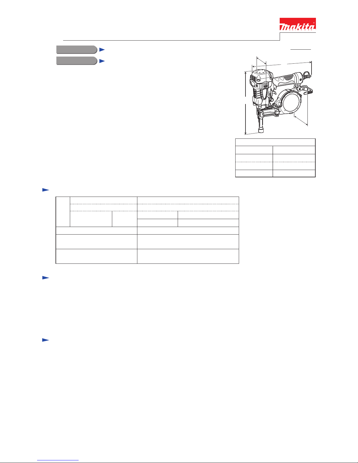
Makita AN250HC User manual

Makita
Makita AN621 Quick start guide

Makita
Makita AF500HP User manual

Makita
Makita AN923 User manual

Makita
Makita AF505N User manual

Makita
Makita AF353 User manual

Makita
Makita PT354D User manual

Makita
Makita AN620H User manual

Makita
Makita AF500HP User manual

Makita
Makita GF600 User manual

Makita
Makita GN900 User manual

Makita
Makita AN454 User manual

Makita
Makita DFN350 User manual