Makita M1902 Manual

June 2016
OFFICIAL USE
for ASC & Sales Shop
Specifications
Standard equipment
Continuous Rating (W)
Voltage (V) Cycle (Hz) Input Output Max Output (W)
110
120
220
230
240
4.6
4.0
2.4
2.3
2.6
50/60
50/60
50/60
50/60
50/60
480
N/A
500
500
580
145
130
225
225
300
550
550
550
550
550
Current (A)
Planer blade 82 (re-sharpenable blade or disposable blade)
Blade gauge assembly
Hex wrench
Sharpening holder assembly (for unit with re-sharpenable blade only)
Guide rule (country-specific)
Dressing stone (country-specific)
Note: The standard equipment may vary by country or model variation.
No load speed: min-1 = rpm
Capacities: mm (")
Shiplapping
Planing width
Planing depth
Protection from electric shock
Power supply cord: m (ft)
Weight according to
EPTA-Procedure 01/ver.2.1*: kg (lbs)
16,000
82 (3-1/4)
9 (11/32)
1 (1/32)
Double insulation
2.7 (5.8)
2.0 (6.6)
* With Planer blade, Dust nozzle
Optional accessories
N/A
Model M1902 is an 82mm Planer with excellent cost performance
that has been developed as a model of Makita-mt-series.
Its main features are:
• Cost performance superior to MODERN M-2900
• New appearance; Features the same design concept as maktec/SSP-Makita
brand series; however, the logo has been replaced by “Makita-mt-” for new
series development.
• Foot on base plate; protects workpiece and blade from scratches and damage
even if the machine is put on workpiece before drum comes to a complete stop.
• Ergonomically designed handle
• Guide rule can be installed.
• V-groove on base for easy chamfer cutting
• Aluminum bracket
Dimensions: mm (")
Width (W)
Height (H)
Length (L) With Foot
157 (6-3/16)
W/O Foot 278 (11)
285 (11-1/4)
160 (6-5/16)
CONCEPT AND MAIN APPLICATIONS
1 / 19
82mm (3-1/4") Planer
Model No. M1902
Description
TECHNICAL INFORMATION
Specifications Model M1902
H
L
W

1INDEX
1INDEX.......................................................................................................................................................................................... 2
2CAUTION .................................................................................................................................................................................... 3
3NECESSARY REPAIRING TOOLS ........................................................................................................................................... 3
4LUBRICANT AND ADHESIVE APPLICATION ...................................................................................................................... 3
5REPAIR ........................................................................................................................................................................................ 4
5-1 Poly V-belt 4-241 ................................................................................................................................................................. 4
5-1-1 Disassembling ............................................................................................................................................................. 4
5-1-2 Assembling.................................................................................................................................................................. 5
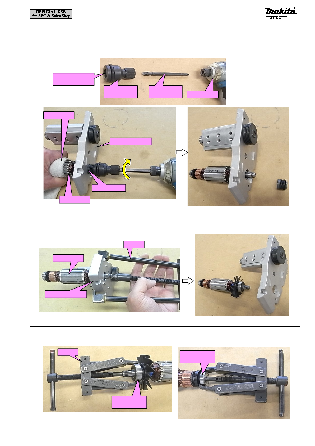
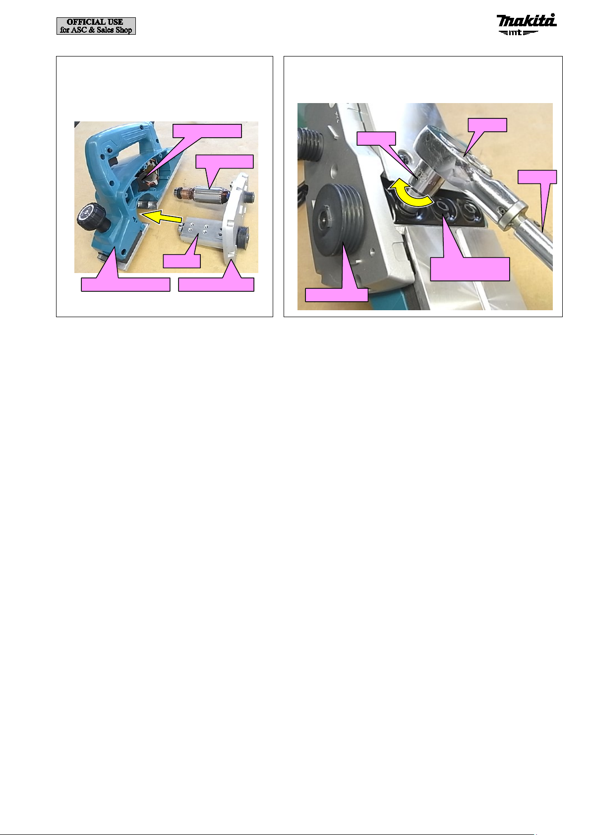
5-2 Armature .............................................................................................................................................................................. 6
5-2-1 Disassembling ............................................................................................................................................................. 6
5-2-2 Assembling.................................................................................................................................................................. 9
5-3 Drum .................................................................................................................................................................................. 11
5-3-1 Disassembling ........................................................................................................................................................... 11
5-3-2 Assembling................................................................................................................................................................ 12
5-4 Front base, Base ................................................................................................................................................................. 14
5-4-1 Disassembling ........................................................................................................................................................... 14
5-4-2 Assembling................................................................................................................................................................ 15
5-5 Foot .................................................................................................................................................................................... 15
5-5-1 Disassembling ........................................................................................................................................................... 15
5-5-2 Assembling................................................................................................................................................................ 15
6Circuit diagram ........................................................................................................................................................................... 16
7Wiring diagram ........................................................................................................................................................................... 17
8TIGHTENING TORQUE SPECIFICATIONS.......................................................................................................................... 19
2 / 19

2CAUTION
Repair the machine in accordance with “Instruction manual” or “Safety instructions”.
Follow the instructions described below in advance before repairing:
· Wear gloves.
· In order to avoid wrong reassembly, draw or write down where and how the parts are assembled, and what are the parts.
It is also recommended to have boxes ready to keep disassembled parts by group.
· Handle the disassembled parts carefully. Clean and wash them properly.
3NECESSARY REPAIRING TOOLS
Code No.
Description
Use for
1R016
1/4" Hex shank bit M6
removing M6x17 Hex socket hex bolt
1R031
Bearing setting pipe 28-20.2
assembling Armature and Drum
1R032
Bearing setting plate 8.2
press-fitting Ball bearing 607ZZ/608ZZ
1R034
Bearing setting plate 12.2
press-fitting Ball bearing 6000DDW
1R045
Gear extractor (large)
removing Armature and Drum
1R219
Torque wrench shaft 7-23N·m
tightening M6x17 Hex socket hex bolt
1R220
Ratchet head 9.5
1R258
V Block
assembling Armature and Drum
1R269
Bearing extractor (small)
removing Ball bearing 6000DDW/607ZZ/608ZZ
4LUBRICANT AND ADHESIVE APPLICATION
Apply the following lubricants and adhesives.
Fig. 4-1
Lubricant
Amount
VG100
a little
Front base
Sliding surface between Front base
and Main frame complete
3 / 19

5REPAIR
5-1 Poly V-belt 4-241
5-1-1 Disassembling
Fig. 5-1-1-1
[1] Loosen two M4x25 Pan head screws, and remove Belt cover.
Fig. 5-1-1-2
[2] Cut the old Poly V-belt 4-241 with cutting pliers.
[3] When you use Poly V-belt 4-241 again, pry it off with a screwdriver while turning either of two V pulleys. Then, Poly V-belt
4-241 can be removed.
Belt cover
M4x25 Pan
head screw
M4x25 Pan
head screw
Poly V-belt
4-241
V pulley 4-37
V pulley 4-20L
4 / 19

5-1-2 Assembling
Fig. 5-1-2-2
[2] Hook Poly V-belt 4-241 to V pulley 4-37 while pressing the positions shown by the red circle and turning either of two V
pulleys.
Note:
· All V-shaped ribs of Poly V-belt 4-241 must be engaged with the grooves of the both of V pulley.
· Be careful not to push Poly V-belt 4-241 so deep that it rubs against Bracket complete.
Fig. 5-1-2-1
[1] Hook Poly V-belt 4-241 to V pulley 4-20L.
Poly V-belt
4-241
V pulley 4-20L
V pulley 4-37
Poly V-belt
4-241
V pulley 4-20L
Poly V-belt 4-241
V pulley
Bracket complete
Bracket complete
Poly V-belt 4-241
5 / 19

5-2 Armature
5-2-1 Disassembling
[1] Remove Poly V-belt 4-241. (5-1-1 Disassembling)
Fig. 5-2-1-2
[3] Loosen M4x22 + Pan head screw, and remove Chip cover.
Fig. 5-2-1-1
[2] Loosen six M6x17 Hex socket hex bolts by turning them counterclockwise with 1R016 and an impact driver, and remove
two 82mm HSS Planer blades and two Drum plates.
1R016
Impact
driver
M6x17 Hex socket
hex bolt (6 pcs.)
82mm HSS
Planer blade
Drum plate
M4x22 + Pan head
screw
Chip cover
Fig. 5-2-1-3
[4] Remove Carbon brushes.
Carbon brush
Carbon brush
6 / 19

Fig. 5-2-1-4
[5] Remove six 4x18 Tapping screws.
4x18 Tapping
screw (6 pcs.)
Fig. 5-2-1-5
[6] Tap Main frame complete with a plastic hammer, and remove the unit of Armature, Drum and Bracket complete.
Main frame
complete
Drum
Armature
Bracket
complete
7 / 19

Fig. 5-2-1-8
[9] Remove Ball bearing 6000DDW and Ball bearing 607ZZ with 1R269.
Fig. 5-2-1-7
[8] Remove Armature from Bracket complete with 1R045.
1R045
Bracket complete
Armature
1R269
Ball bearing
6000DDW
Ball bearing
607ZZ
Fig. 5-2-1-6
[7] Hold Armature with a waste cloth, and remove V pulley 4-20L from Bracket complete by turning it clockwise with a bit
adapter assembly, double ended phillips bit and impact driver.
Impact driver
V pulley 4-20L
Double ended
phillips bit
Bit adapter
assembly
Armature
Waste cloth
Square drive :
12.7mm (1/2")
Bracket complete
8 / 19

5-2-2 Assembling
[1] Assemble by reversing the disassembly procedure.
Fig. 5-2-2-3
[5] Hold Armature with a waste cloth, and fasten moderately V pulley 4-20L to Bracket complete by turning it counterclockwise
with a bit adapter assembly, double ended phillips bit and impact driver.
Fig. 5-2-2-1
[2] Set the following parts in the order from the bottom:
(1) 1R034
(2) Ball bearing 6000DDW
(3) Armature
(4) Ball bearing 607ZZ
(5) 1R032
[3] Press-fit the armature shaft into Ball bearing 607ZZ and
Ball bearing 6000DDW.
Fig. 5-2-2-2
[4] Assemble Armature to Bracket complete with 1R031
and 1R258.
1R032
Ball bearing
607ZZ
1R034
Ball bearing
6000DDW
Armature
Bracket
complete
1R258
1R031
Armature
Impact driver
V pulley 4-20L
Double ended
phillips bit
Bit adapter
assembly
Armature
Waste cloth
Square drive :
12.7mm (1/2")
Bracket complete
9 / 19

Fig. 5-2-2-4
[6] Assemble the unit of Armature, Drum and
Bracket complete to Main frame complete.
Note: Be careful not to lose Assist fan guide.
Main frame complete
Bracket complete
Assist fan guide
Armature
Drum
Fig. 5-2-2-5
[7] Tighten six M6x17 Hex socket hex bolts to 6 to 9N·m from the
V pulley 4-37 side with 1R219, 1R220 and Socket 9.
1R220
1R219
Socket 9
V pulley 4-37
M6x17 Hex socket
hex bolt (6 pcs.)
10 / 19

5-3 Drum
5-3-1 Disassembling
[1] Remove the unit of Armature, Drum and Bracket complete. (5-1-1 Disassembling)
Fig. 5-3-1-2
[3] Remove Drum from Bracket complete with 1R045.
1R045
Bracket complete
Armature
Drum
Fig. 5-3-1-1
[2] Hold Drum with a waste cloth, and remove V pulley 4-37 from Bracket complete by turning it counterclockwise with a bit
adapter assembly, double ended phillips bit and impact driver.
Impact driver
V pulley 4-37
Double ended
phillips bit
Bit adapter
assembly
Drum
Waste cloth
Square drive :
12.7mm (1/2")
Bracket complete
11 / 19

5-3-2 Assembling
[1] Assemble by reversing the disassembly procedure.
1R269
Ball bearing
6000DDW
Ball bearing
608ZZ
Fig. 5-3-1-3
[4] Remove Ball bearing 6000DDW and Ball bearing 608ZZ with 1R269.
Fig. 5-3-2-1
[2] Set the following parts in the order from the bottom:
(1) 1R034
(2) Ball bearing 6000DDW
(3) Drum
(4) Ball bearing 607ZZ
(5) 1R032
[3] Press-fit the shaft of Drum into Ball bearing 607ZZ and
Ball bearing 6000DDW.
Fig. 5-3-2-2
[4] Assemble Drum to Bracket complete with 1R031 and
1R258.
1R032
Ball bearing
607ZZ
1R034
Ball bearing
6000DDW
Drum
1R031
1R258
Drum
Bracket complete
12 / 19

[6] Assemble the unit of Armature, Drum and Bracket complete to Main frame complete. (Fig. 5-2-2-4)
[7] Tighten six M6x17 Hex socket hex bolts to 6 to 9N·m from the V pulley 4-37 side with 1R219, 1R220 and Socket 9.
(Fig. 5-2-2-5)
Fig. 5-3-2-3
[5] Hold Drum with a waste cloth, and fasten carefully V pulley 4-37 to Bracket complete by turning it clockwise with a bit
adapter assembly, double ended phillips bit and impact driver.
Impact driver
V pulley 4-37
Double ended
phillips bit
Bit adapter
assembly
Drum
Waste cloth
Square drive :
12.7mm (1/2")
Bracket complete
13 / 19

5-4 Front base, Base
5-4-1 Disassembling
Fig. 5-4-1-1
[1] Remove Front base by turning Knob 44 counterclockwise.
Knob 44
Knob 44
Flat
washer 10
Compression
spring 18
Rubber
packing
Front base
Fig. 5-4-1-2
[2] Remove Base, Foot and Torsion spring 7 by removing four 4x18 Tapping screws.
4x18 Tapping
screw (4 pcs.)
Foot
Base
Torsion
spring 7
14 / 19

5-4-2 Assembling
[1] Assemble Foot to Main frame complete. (5-5-2 Assembling)
5-5 Foot
5-5-1 Disassembling
Remove Foot. (5-4-1 Disassembling)
5-5-2 Assembling
Fig. 5-4-2-1
[2] Align the height of Base and Front base by turning
Knob 44.
Base
Front base
Knob 44
Fig. 5-4-2-2
[3] Align the “0” on the scale label on Knob 44 with the
triangle mark on Main frame complete, and replace the
scale label with a new one,
Note: If any of Front base, Base, Main frame complete,
Knob 44 is replaced, replace the scale label of Knob
44 with a new one because the indication of the
cutting depth may be misaligned.
Triangle mark
Knob 44
Scale label
Fig. 5-5-2-1
[1] Assemble Torsion spring 7 to Foot.
Fig. 5-5-2-2
[2] Hook the one leg of Torsion spring 7 to Base.
Torsion
spring 7
Foot
Torsion
spring 7
Base
Foot
15 / 19

6Circuit diagram
Fig. 6-1
↑
Circuit diagram of Switch
Non-insulated
connector
Power supply cord
Choke coil
(if used)
Viewed from
commutator end
Black/AWG18, single wire
Black or Brown
Terminal block
or Closed end
splice
Noise suppressor
(if used)
(1)
Switch
Insulated connector
(M4)
Non-insulated connector
Choke coil (if used)
Polyolefin tube
Polyolefin tube
(2)
Field
AWG: American wire gauge
Orange/AWG18
Black/AWG18, single wire
White/ AW G 20
Orange/AWG18
White/ AW G 20
Purple/AWG18
Purple/AWG18
White or Blue
If Clamp washer is used
Corner clutch
Assemble Clamp washer to Switch as shown below so that Clamp washer does not touch the ribs on Switch.
Clamp washer
Switch
16 / 19

7Wiring diagram
Fig. 7-1
Wiring around Field
Choke coil (if used)
Field
Field lead wire
Motor housing
Field lead wire
Field lead wire
Field lead wire
Polyolefin tube
Polyolefin tube
Assemble Field to Motor housing as shown below.
17 / 19

Fig. 7-2
Wiring to Main frame complete
Noise suppressor (if used)
Terminal block (if used)
Switch
Lead wire
holder B
Inner
wall
Inner wall
Lead wire holder A
If Terminal block is used, do not put the
lead wires under Terminal block.
Rib
Rib
Put Noise suppressor in this space so that the lead wires are routed as shown below.
(If Noise suppressor is used.)
Boss
Field
Rib on Terminal plate
Put Field lead wires
(orange, purple)
between the rib on
Terminal plate and the
inner wall.
Put Field lead wires into
Lead wire holder A so
that they are not
loosened between Lead
wire holder A and Field.
Do not put the lead wires on the ribs and Boss.
Put the lead wire (purple) into Lead wire holder B.
A
A
Cross section of A-A
Edge
Edge
Pass-through slot
Route Field lead wires through the
pass-through slot on Motor housing so as
not to damage them with edge.
Main frame complete
18 / 19

8TIGHTENING TORQUE SPECIFICATIONS
V pulley 4-20L
Armature
V pulley 4-20L
3.0 and more
1
V pulley 4-37
Drum
V pulley 4-37
3.0 and more
1
Parts to fasten Fastener
Tightening torque
(N
・
m) Q’ty
19 / 19
Other manuals for M1902
8
Table of contents
Other Makita Planer manuals

Makita
Makita PC1100 User manual

Makita
Makita N1900B User manual

Makita
Makita 1911B User manual

Makita
Makita M1902 User manual

Makita
Makita DKP180RFJ User manual

Makita
Makita 1806B User manual

Makita
Makita N1923B User manual

Makita
Makita 1902 User manual

Makita
Makita 2012NB User manual

Makita
Makita KP312 User manual

Makita
Makita KP0810 Manual

Makita
Makita KP0810 User manual

Makita
Makita PC5010C User manual

Makita
Makita KP0800X User manual

Makita
Makita KP0800 User manual

Makita
Makita N1900B User manual

Makita
Makita BKP180RFJ User manual

Makita
Makita 1911B User manual

Makita
Makita PC5010C User manual

Makita
Makita KP0800 User manual