Makita PC5001C Manual

Models No.
Description
PRODUCT
TECHNICAL INFORMATION
CONCEPT AND MAIN APPLICATIONS
Specification
Standard equipment
Optional accessories
P 1/ 9
Dimensions: mm (")
Width (W)
Height (H)
Length (L)
Model No.
479 (18-13/16) 437 (17-1/8)
PC5001C PC5000C
195 (7-5/8)
182 (7-1/8) 235 (9-1/4)
Note: The standard equipment for the tools shown above may vary by country.
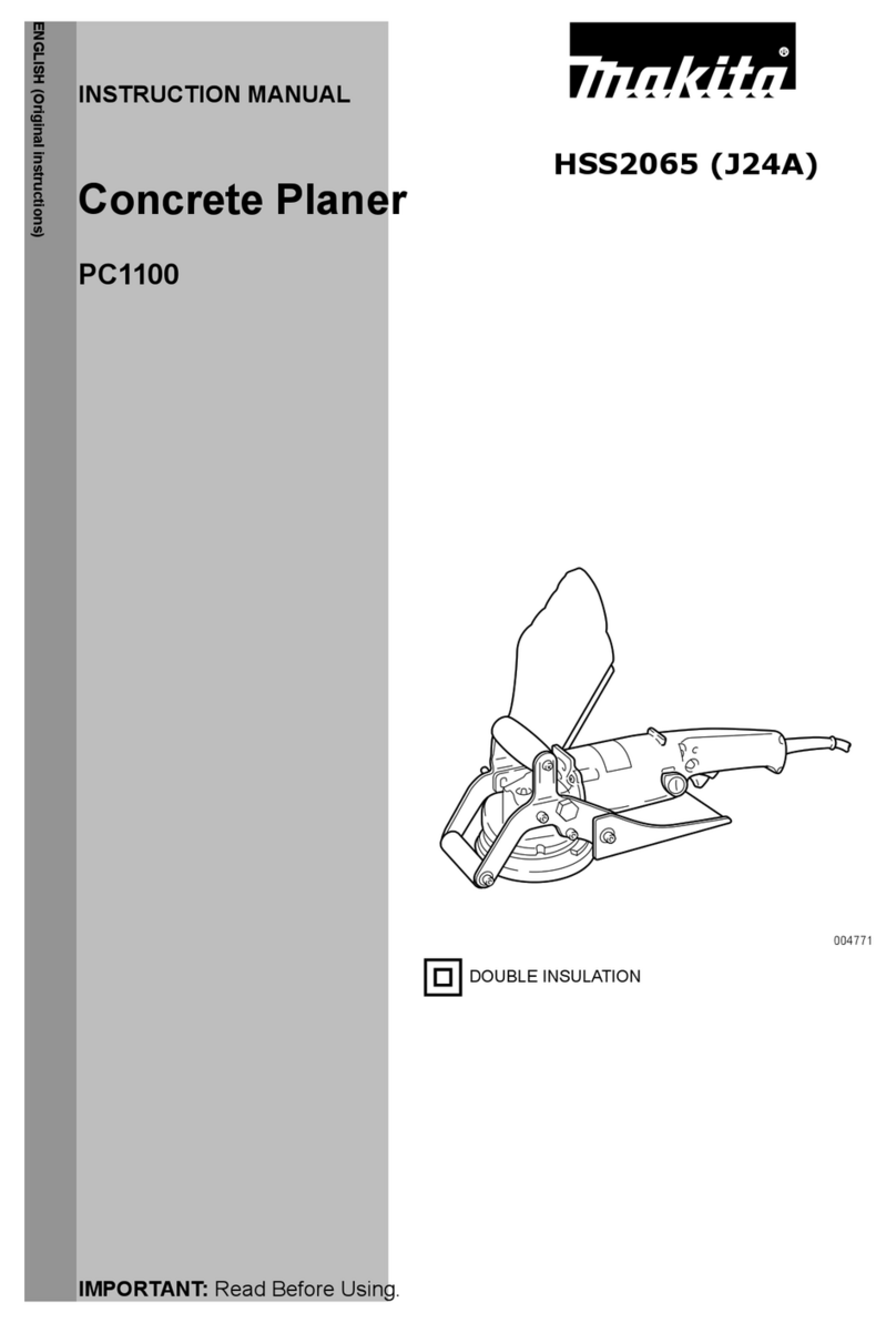
PC5001C, PC5000C
Concrete Planer 125mm (5")
Models PC5001C and PC5000C are upgraded sister tools
of PC1100. Features electronic control, allowing for
use of powerful 1,400W motor.
Listed below are specification differences between
PC5001C and PC5000C.
Offset diamond wheel 125mm (5") ........ 1 pc
Hex wrench 5 .......................................... 1 pc
Dust bag assembly .................................. 1 pc
Lock nut wrench ............... 1 pc
Brush set (for spare) ......... 1 set
Steel carrying case ............ 1 pc
Model No.
No load speed: min.-1 = rpm
Type
Hole diameter: mm (")
Wheel
Protection against electric shock
Power supply cord: m (ft)
PC5000CPC5001C
5.0 (16.4)
4.0 (8.9)
Offset diamond wheel
Diameter: mm (") 125 (5)
Double insulation
22.23 (7/8)
5.1 (11.2)
3.4 (7.6)4.5 (9.9)
10,000
Built-in dust extraction Yes
Offset diamond wheel 125mm (5")
Offset diamond wheel 110mm (4-3/8")
Brush set (includes Brush A and Brush B)
Offset diamond wheel 125mm (5")
Brush set (includes Brush A and Brush B)
L
H
W
Continuous Rating (W)
Voltage (V) Cycle (Hz) Input Output
1,000
Max. Output (W)
110
120
220
230
240
13
10
6.7
6.4
6.1
50/60
50/60
50/60
50/60
50/60
1,400
---
1,400
1,400
1,400
2,600
2,600
2,200
2,200
2,600
Current (A)
600
1,000
1,000
1,000
Yes
Yes
Yes
Yes
Constant speed control
LED indication lamp
Soft start
Electronic current limiter
Anti-restart function
Electronic
control
Yes
PC5001C PC5000C
L
H
W
PC5001C
PC5000C
Model No.
Loop handle,
D-shaped
Top handle
Auxiliary handle
Yes
No
Base and Front roller
PC5001C PC5000C
Net weight: kg (lbs)
Weight according to
EPTA-Procedure 01/2003: kg (lbs)

P 2/ 9
Repair
CAUTION: Remove the offset diamond wheel from the machine for safety before repair/ main-
tenance in accordance with the instruction manual!
[1] NECESSARY REPAIRING TOOLS
[2] LUBRICATIONS
[3] DISASSEMBLY/ASSEMBLY
[3]-1. Armature, Spiral bevel gear 11
Fig. 1
Code No. Description Use for
1R004 Retaining ring S pliers ST-2 Removing / Assembling Ring spring 11
1R029
1R034
1R268 Spring pin extractor 3 Removing Shoulder pin 5 from Pin cap
1R269 Bearing Extractor Removing Ball bearings 608DDW and 696ZZ
1R291 Retaining ring S & R pliers Removing Retaining ring R-30 from Gear housing
1R350 Ring 60 Supporting Skirt complete when removing Spindle from Spiral bevel gear 35A
Bearing setting pipe 23-15.2 Assembling Spiral bevel gear 35A to Spindle
Bearing setting pipe 12.2
Item No.
Apply Makita grease SG.No.0 to the following portions designated with the black triangle to protect parts
and product from unusual abrasion.
Description Portion to lubricate Amount
20g
DISASSEMBLING
4
M7 Hex nut
M6x12 Hex socket head bolt
Carbon brush
Brush holder cap
Brush holder cap
Front roller
Front roller holder
Spiral bevel gear 11
Remove Carbon brushes to remove Armature later.
Separate Front roller and Front roller holder from the machine by removing two M6x12 Hex socket head bolts.
(1) Disassemble Front roller as illustrated in Fig. 2.
Gear housing complete Gear room for engaging Spiral bevel gear 11 with Spiral bevel gear 35A
4
Fig. 2

P 3/ 9
Repair
[3] DISASSEMBLY/ASSEMBLY
[3]-1. Armature, Spiral bevel gear 11 (cont.)
DISASSEMBLING
Spacer B (2pcs.)
Grip
Unscrewing M8x25 Hex socket head bolts,
disassemble Grip and Spacer (2pcs.).
Remove M6x12 Hex socket head bolt, then pull
Base section (Base and Base holder) toward Handle.
M8x25 Hex socket head bolt (2pcs.)
M4x10 Pan
head screw
(3pcs.)
M5x35 Pan head
screw (4pcs.)
5x25 Tapping
screw (4pcs.)
Separator
Remove Separator by
unscrewing three M4x10
Pan head scerws.
Remove four 5x25 Tapping screws,
then remove Gear housing together
with Armature.
Locking M7 Hex nut with
Wrench 11, turn Armature
clockwise by hand.
Armature can be disassembled by pulling
it off. Pay attention not to lose M7 Hex
nut and Spiral bevel gear 11.
Locking Spindle with shaft lock,
grip the Square portion of Fan 85
with Monkey wrench, and turn
the wrench counterclockwise.
Remove four Max Pan head
screws. Skirt complete can be
separated from Gear housing.
Square portion of Fan 85
Monkey wrench
Fan 85
Gear housing
Armature
Wrench 11
M6x12 Hex socket
head bolt
(2) Disassemble Grip and Base section from the machine as illustrated in Fig. 3.
Spiral bevel gear 11 and Armature can be disassembled as illustrated in Fig. 4.
Base
Base holder
Fig. 3
Fig. 4
Skirt
complete
Gear housing
M7 Hex nut
Spiral bevel
gear 11
M7 Hex nut
Armature
Handle

P 4/ 9
Repair
[3] DISASSEMBLY/ASSEMBLY
[3]-1. Armature, Spiral bevel gear 11
DISASSEMBLING
M7 Hex nut
Spray some lubricant
to M7 Hex nut.
Hold M7 Hex nut with wrench 11 and
turn Armature wrapped with cloth
clockwise using water pump pliers.
Water pump
pliers
Cloth to protect ArmatureArmature
M7 Hex nut
Wrench 11
Spiral bevel
gear 11
M7 Hex nut
Armature
Armature can be disassembled.
Pay attention not to lose M7 Hex nut and
Spiral bevel gear 11.
Fig. 4-S
Fig. 5
(2-S) If it is difficult to remove Armature by hand;
1) spray some lubricant to M7 Hex nut.
2) turn Armature with water pump pliers while holding M7 Hex nut with wrench 11.
Refer to Fig. 4-S.
(3) Retaining ring R-30, Flat washer 22, Ball bearing 6000DDW and Rubber ring 26 are still left in Gear housing.
They can be disassembled as illustrated in Fig. 5.
Retaining
ring R-30
Flat washer 22
Strike the edge of Gear housing with Plastic hammer.
Ball bearing 6000DDW and Rubber ring 26 come out together with
M7 Hex nut, Spiral bevel gear 11 and Armature.
Remove Retaining ring R-30 and Flat washer 22. Secure Armature and Spiral bevel gear 11, and then
assemble them to Gear housing using M7 Hex nut.
Spiral bevel gear 11 functions as a tool for removing
Ball bearing 6000DDW at this time.
Wrench 11 for
holding M7 Hex nut
M7 Hex nut
M7 Hex nut Spiral bevel gear 11
Rubber ring 26 Ball bearing 6000DDW

P 5/ 9
Repair
[3] DISASSEMBLY/ASSEMBLY
[3]-1. Armature, Spiral bevel gear 11 (cont.)
[3]-2. Skirt section (Spiral bevel gear 35A, Ball bearings, Spindle)
DISASSEMBLING
ASSEMBLING
Flat washer 22
(1) Assemble Armature to Gear housing as illustrated in Fig. 6.
(2) Take the disassembling step in reverse. Refer to Fig. 4, 3, 2.
Assemble Rubber ring 26, Ball bearing 6000DDW
and Flat Washer 22 to Gear housing.
Insert Armature into Ball bearing 6000DDW.
Holding M7 Hex nut with Wrench 11,
turn Armature counterclockwise.
Rubber
ring 26
Ball bearing
6000DDW Retaining
ring R-30
Fig. 6
Wrench 11
M7 Hex nut
(1) Separate Skirt complete from Gear housing, as illustrated in Figs. 3 and 4.
But no need to separate Gear housing from Motor housing.
(2) Disassemble Gear and spindle from Skirt as illustrated in Fig. 7.
Note: Do not deform Labyrinth ring on Spindle.
Spiral bevel
gear 35A
Ball bearing
696ZZ Skirt complete
Ring spring 11
1R004
1R269
1R350
Spiral bevel
gear 35A
Spiral bevel
gear 35A
Spindle
Ring spring 11
Remove Ball bearing 696ZZ
as illustrated below.
Remove Spindle with 1R350 and Arbor press.
While opening the cut portion of Ring spring 11 with 1R004,
lift up the Ring spring with screwdriver as illustrated below.
Ring spring 11 can be removed.
Figs. 7
Labyrinth ring

1R029
P 6/ 9
Repair
[3] DISASSEMBLY/ASSEMBLY
[3]-2. Skirt section (Spiral bevel gear 35A, Ball bearings, Spindle) (cont.)
DISASSEMBLING
ASSEMBLING
M3x6 Pan
head screw
(3pcs.)
M3x6 Pan head
screw (3pcs.)
Secure Ball bearing 6202DDW
with Bearing retainer 39.
Bearing
retainer 39
O ring 48
Ball bearing
6202DDW
Flat washer 15
Remove Bearing retainer 39 by
removing three M3x6 Pan head
screws.
Put Flat washer 15 on Ball bearing 6202DDW,
then assemble Ball bearing 6202DDW to Skirt
with Arbor press and 1R029.
(2) Remove the damaged Ball bearing 6202DDW as illustrated in Fig. 8.
Note: Disassembling Spindle section causes a damage to Ball bearing 6202DDW. Therefore, do not reassemble the removed
Ball bearing 6202DDW. Replace it with the fresh Ball bearing 6202DDW.
(1) Assemble Skirt section as illustrated in Fig. 9.
Remove Ball bearing 6202DDW and Flat washer 19
with Arbor press from the opposite side of Bearing
retainer 39.
Ball bearing
6202DDW
Flat
washer 15
Figs. 8
Figs. 9
Bearing
retainer 39
Make sure that O ring 48 is
assembled to Skirt complete.
Stand Spindle on 1R034. Insert Spindle in place by applying 1R029 to Spiral bevel gear 35A and
pressing down using Arbor press.
Note: Do not deform Labyrinth ring on Spindle.
1R034 Spiral bevel
gear 35A
1R029
Spindle Spindle
Labyrinth ring

P 7/ 9
Repair
[3] DISASSEMBLY/ASSEMBLY
[3] -3. Shaft lock mechanism
DISASSEMBLING
ASSEMBLING
Applying 1R268 to Shoulder pin 5 through the small hole
on Pin cap, strike 1R268 with Hammer.
Shoulder pin 5 comes out from Gear housing complete.
Release 1R268 from Pin cap carefully so as
not to sling Pin cap by Compression spring 8.
Shoulder pin 5
Pin cap
Impossible to reuse Pin cap, because
removal of Shoulder pin 4 damages the
Pin cap.
Pin cap
Pin cap
Compression
spring 8
1R268
1R350
Fig. 10 Fig. 11
(1) Remove Front roller and Base section as illustrated in Figs. 2 and 3.
(2) Remove skirt complete as illustrated in Fig. 4. But, no need to separate Gear housing from Motor housing.
(3) Now, Shaft lock mechanism can be disassembled as illustrated in Figs. 10 and 11.
Fig. 12 Fig. 13
(1) Be sure to use new Pin cap for replacement and to remove all the plastic dust on Shoulder pin 5. (Fig. 12)
(2) Assemble the components for Shaft lock mechanism as illustrated in Fig. 13.
Plastic dust
O ring 7
Shoulder pin 5
Shoulder
pin 5
Assemble Pin cap by pressing it
to Shoulder pin 7.
Insert Shoulder pin 5
through the hole of Gear
housing complete. Pin cap
Compression spring 8

P 8/ 9
Circuit diagram
Wiring diagram
Wiring of Pick-up coil
White
Color index of lead wires' sheath
Black Orange
Red
Insulated connector
Terminal block
Fig. D-1
Fig. D-2
Brown Lead wire is used
for some countries.
Purple or blue Lead wire
is used for some countries.
Power
supply cord
Field
Controller
Pick-up coil
Noise suppressor
(if used)
Pick-up coil
Lead wire holder
of Sleeve
Sleeve
Assemble Pick-up coil to Sleeve.
Put the Lead wires into Lead wire
holder as illustrated below.
Blue Lead wire is used for
some countries.
Lead wire holder
of Sleeve

P 9/ 9
Wiring diagram
Wiring in Motor Housing
Wiring in Handle
Fig. D-4
Fig. D-5
Pick-up Coil
Put Controller’s lead wire and Field’s
Lead wire as illustrated below.
Grip
Brush holder
Pull out Field lead wires (orange and white) from the illustrated opening of Motor housing.
Brush holder
Makita
logo side
Field lead wire
(white)
Field lead wire
(orange)
Controller’s
Lead wire (orange)
Switch Lever
Switch Lever
Field’s
Lead wire
(orange)
Controller’s
Lead wire (black)
Controller’s
Lead wire (red, or blue)
Wiring under Switch
Controller
side
Controller
Switch lever side
Wiring to Switch
(viewing from Handle set (L) side)
(viewing from Handle set (R) side)
Handle
Switch
Noise suppressor
Terminal block Insulated
Connector
Fix Field lead wires (orange, white)
with this Lead wire holder.
Pass Field lead wires (orange, white)
between Handle set and Controller setting rib.
Pass Pick-up coil’s lead wires (black, white) between Handle set
and Controller setting rib.
Fix Controller’s lead wires (black,
orange, red, white) with this Lead
wire holder.
This manual suits for next models
1
Table of contents
Other Makita Planer manuals

Makita
Makita KP312 User manual

Makita
Makita DKP140 User manual

Makita
Makita 1806B User manual

Makita
Makita KP0800 User manual

Makita
Makita PC5000C User manual
Makita
Makita 1902 User manual

Makita
Makita 1806B User manual

Makita
Makita KP312 User manual

Makita
Makita KP0800 User manual

Makita
Makita DKP180ZJ User manual

Makita
Makita 1804N User manual

Makita
Makita M1901 User manual

Makita
Makita KP0810 User manual

Makita
Makita KP0810 User manual

Makita
Makita KP312S User manual

Makita
Makita 1912B User manual

Makita
Makita 2012NB User manual
Makita
Makita 1902 User manual

Makita
Makita KP0810 User manual

Makita
Makita HG 1100 User manual