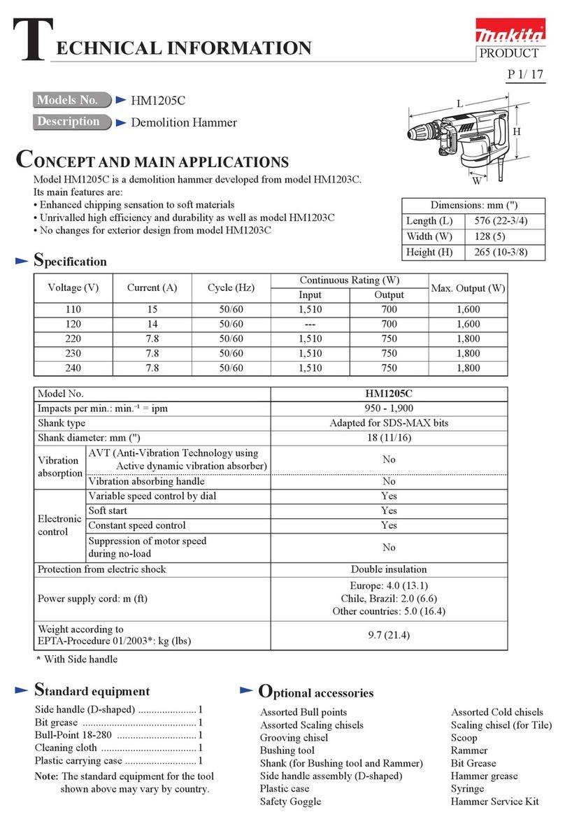
Makita DTM41 Manual

Models DTM41, DTM51 have been developed based on
the current BTM40/DTM40, BTM50/DTM50.
The two models feature the tool-less accessory change system,
in addition to the benefits of the current models.
These products are powered by the following Li-ion batteries:
DTM41 by 14.4V Li-ion batteries of BL1415 (1.3Ah)/ BL1415N,
BL1415NA (1.5Ah)/ BL1430 (3.0Ah), BL1430A (3.0Ah)/ BL1440 (4.0Ah)/
BL1450 (5.0Ah)
DTM51 by 18V Li-ion batteries of BL1815 (1.3Ah)/ BL1815N (1.5Ah)/
BL1820 (2.0Ah)/ BL1830 (3.0Ah)/ BL1840 (4.0Ah)/ BL1850 (5.0Ah)
DTM41, DTM51
Model No.
Description
CONCEPT AND MAIN APPLICATIONS
Specification
Dimensions: mm (")
Width (W)
Height (H)
Length (L) 326 (12-7/8)*1/
340 (13-3/8)*2
80 (3-1/8)
122 (4-13/16)104 (4-1/8)
DTM51DTM41
Cordless Multi tools
Standard equipment
Note: The standard equipment may vary by country or model variation.
Oscillating multi tool accessories
[equivalent to BOSCH OIS (Oscillating Interface System)]
“Dust attachment” for Sanding pad (for European countries only)
“Tool box” for storing oscillating multi tool accessories (for some countries only)
Plastic carrying case or Tool bag (for some countries only)
Battery*8
Charger*8
Battery cover*9
Optional accessories
Weight according to
EPTA-Procedure 01/2003*3: kg (lbs)
2.0 (4.3)*4
2.1 (4.7)*5
2.0 (4.4)*6
2.2 (4.9)*7
YesVariable speed control by dial
Anti-restart function
Oscillations per minute: opm=minˉ¹
Oscillating multi tool accessories
*3 with Battery and Vacuum attachment, without Sanding pad
*4 With BL1415 or BL1415N *5 With BL1430, BL1440 or BL1450
*6 With BL1815, BL1815N or BL1820 *7 With BL1830, BL1840 or BL1850
6,000 - 20,000
Oscillation angle, left/right: degree [°] 1.6 (3.2 total)
Makita oscillating multi tool accessories
equivalent to BOSCH OIS (Oscillating Interface System)
Soft start Yes
Electronic
control
Yes
Oscillating multi tool accessories
[equivalent to BOSCH OIS (Oscillating Interface System)]
Triangular abrasive papers (Hook & loop type)
Tool box (for storing oscillating multi tool accessories)
Dust attachment set
Li-ion battery BL1415 (for DTM41)
Li-ion battery BL1415N (for DTM41)
Li-ion battery BL1415NA (for DTM41)
Li-ion battery BL1430 (for DTM41)
Li-ion battery BL1440 (for DTM41)
Li-ion battery BL1450 (for DTM41)
Li-ion battery BL1815 (for DTM51)
Li-ion battery BL1815N (for DTM51)
Li-ion battery BL1820 (for DTM51)
Li-ion battery BL1830 (for DTM51)
Li-ion battery BL1840 (for DTM51)
Li-ion battery BL1850 (for DTM51)
Fast charger DC18RC
Charger DC18SD
Charger DC24SC
Four port multi charger DC18SF
Automotive charger DC18SE
PRODUCT
P 1/ 12
DTM41*2
W
L
H
Specification Model
Battery
Cell
Voltage: V
Capacity: Ah
Li-ion
14.4 18
DTM41 DTM51
Max output: W 390340
Energy capacity: Ah
Charging time (approx.): min.
DTM51*2
*8: Battery and charger are not supplied with “Z” model *9: Supplied with the same quantity of extra Battery
TECHNICAL INFORMATION
1.3, 1.5, 2.0, 3.0, 4.0, 5.01.3, 1.5, 3.0, 4.0, 5.0
24, 27, 36, 54, 72, 9019, 22, 44, 58, 72
15, 15, 24, 22, 36, 45 with DC18RC15, 15, 22, 36, 45 with DC18RC
OFFICIAL USE
for ASC & Sales Shop
*1 With BL1815, BL1815N or BL1820/
BL1415 or BL1415N
*2 With BL1830, BL1840 or BL1850/
BL1430, BL1440 or BL1450

P 2/12
Repair
[1] NECESSARY REPAIRING TOOLS
CAUTION: Repair the machine in accordance with “Instruction manual” or “Safety instructions”.
Code No. Description Use for
1R027 Bearing setting pipe 18-10.2 holding Crank housing complete when disassembling Lever
1R233 Round bar for Arbor 4-100 removing Pin 5 when disassembling Lever
1R269
1R291
1R306
Bearing extractor removing Bearing box from the drive end of Armature shaft
Retaining ring S and R pliers removing Retaining ring S-7 from the drive end of Armature shaft
Ring spring removing jig holding 1R233 when disassembling Lever
[2] LUBRICATION
Bearing box
Apply Makita grease FA No.2/ Makita grease N No.2 to the following portions designated with the black/ gray
triangles to protect parts and product from unusual abrasion.
Fig. 1
Item No. Description
O ring 35 whole portion a little
4 g
a little
Crank housing complete
AmountPortion to lubricate
Connector portion
Tip portion of Driver

P 3/12
Repair
[3]DISASSEMBLY/ASSEMBLY
[3]-1.Armature
DISASSEMBLING
1. Separate Battery housing R/ L from Motor housing
by unscrewing two 4x20 Tapping screws.
2. Separate Cushion rubbers from Motor
housing.
3. Separate Handle cover complete by unscrewing
four 3x16 Tapping screws.
4. Disconnect Carbon brushes from Armature’s
commutator by pulling off Brush holders.
Handle cover
complete
Cushion rubber
(1) For disassembling Armature, remove Battery housing R/L, Handle cover, Lower/ Upper head covers etc.
as drawn in Fig. 2.
Brush holder
Line filter
Brush holder
Lock
position
Release
position
Lever
Lower head cover
6. Remove Lower head cover by unscrewing
two 4x20 Tapping screws.
Holder bolt
Upper head cover
Lever
7. Return Lever a little to the lock position, then remove Upper head cover.
5. Shift Lever fully to the release position from
the lock position, then pull off Holder bolt.
Fig. 2
Battery housing R
Battery housing L

P 4/12
Repair
DISASSEMBLING
4A. If Armature remains in Motor housing in the step 3,
pry up Bearing retainer with Slotted head screwdrivers.
(2) Separating Crank housing complete from Motor housing, remove Armature from Crank housing complete. (Fig. 3)
(3) Disassemble the parts that mounted to the drive end of Armature as drawn in Fig. 4.
1. Remove four 4x20
Tapping screws.
1. Remove Retaining
ring S-7 with 1R291.
2. Remove Bearing box
with 1R269.
3. With 1R269, remove Ball bearing 629DDW together
with Balancer, Flat washer 7 and Sphere bearing 706.
2. Tapping the edge of Motor
housing with plastic hammer,
reserve the gap between
Crank housing section and
Motor housing to insert
screwdrivers.
3. Insert 2 slotted head screwdrivers into the gap
between Motor housing and Crank housing
section. Then, remove Crank housing section
by prying it up with the screwdrivers.
Fig. 3
Fig. 4
4. Remove Armature section by tapping
the edge of Crank housing complete.
Crank housing complete
Armature
Bearing box
Bearing box
O ring 35
Bearing
retainer
Ball bearing
629DDW
Balancer
Flat washer 7
Sphere bearing 706
Retaining ring S-7
[3] DISASSEMBLY/ASSEMBLY
[3] -1. Armature (cont.)

P 5/12
Repair
DISASSEMBLING
ASSEMBLING
(4) Remove Bearing retainer and Ball bearing 627DDW as drawn in Fig. 5.
(1) Assemble Ball bearing 627DDW to the commutator end of Armature. (Refer to Fig. 5.)
(2) Assemble the component parts to the drive end of Armature by reversing the disassembly procedure.
(Refer to Figs. 5 and 4.)
(3) Assemble the Armature section to Crank housing complete as drawn in Fig. 6.
Note: For easy assembling of Armature section, heat Crank housing complete with a heat gun after setting Connector
as drawn in Fig. 7.
2. By using with 1R269, Remove Ball bearing 627DDW
from the commutator end of Armature.
1. Remove Bearing retainer
from the drive end of Armature.
Fig. 5
Bearing
retainer
Ball bearing
627DDW
2. Heat Crank housing complete
with a heat gun.
Armature section
Crank housing
complete
Fig. 6
Fig. 7
1. Set Connector to the center.
Projection of
Motor housing
Notch of
Yoke unit
Switch lever side
(4) If Yoke unit is disassembled or replaced, re-assemble Yoke unit as drawn in Fig. 7.
Handle cover
complete side
Fitting the notch of Yoke unit to
the projection of Motor housing,
assemble Yoke unit to Motor housing.
[3] DISASSEMBLY/ASSEMBLY
[3] -1. Armature (cont.)

P 6/12
Repair
ASSEMBLING
[3] -2. Crank housing complete
DISASSEMBLING
(5) Assemble Crank housing complete and Armature section to Motor housing as drawn in Fig. 8.
Fig. 8
Fig. 9
Fig. 10
Be sure to the following matters, when assembling Armature section
to Motor housing, because Yoke unit has very strong magnet force.
1. Do not pinch your finger between Motor housing
and Armature fan.
2. Do not scratch Winding portion, Commutator of
Armature with Baffle plate or edge of Yoke unit.
Commutator of
Armature
Winding portion
Lock position
Release
position
Lever
Holder bolt
Ram of Arbor press
1. Install 1R306 on the ram of Arbor press.
Then, set 1R233 to 1R306. And then, supporting
Crank housing complete with 1R027,
press Pin 5 out from Crank housing complete.
2. Unscrew M4x6 Pan head screw and remove Leaf spring,
Lever and Turn block from Crank housing complete.
1R306
1R027
1R233
M4x6
Pan head
screw
Shift Lever fully to the release position from
the lock position, then pull off Holder bolt.
(1) Disassemble Crank housing complete and Armature from Motor housing as drawn in Figs. 2 and 3.
Note: Holder bolt has to be removed before disassembling Lever. Otherwise, it is impossible to remove the bolt. (Fig. 9)
(2) Disassemble Lever section from Crank housing complete as drawn in Fig. 10.
Pin 5
Turn block
Lever
Leaf spring
Pin 5
Note in Disassembling:
Crank housing complete is a factory assembled part,
and it is impossible to replace its inner component
parts. Replace it with an assembled part.
[3] DISASSEMBLY/ASSEMBLY
[3] -1. Armature (cont.)

P 7/ 12
Repair
[3] DISASSEMBLY/ASSEMBLY
[3] -2. Crank housing complete (cont.)
[3] -3. Switch Lever
ASSEMBLING
DISASSEMBLING
Fig. 11
Fig. 12
(1) Assemble Lever section to Crank housing complete as drawn in Fig. 11.
Turn block
round portion
Leaf spring
1. Set Turn block while aligning
its round portion to Lever’s
round portion.
4. Pin 5 has to be pushed into Crank housing complete
until Pin’s end comes to the same level to the surface of
Crank housing complete.
2. Mount Leaf spring to Lever. 3. Set Lever together with Turn block and
Leaf spring to Crank housing complete.
5. Tighten Leaf spring to Crank housing complete
with M4x6 Pan head screw.
Note: Be sure to tighten the screw after inserting
Pin 5 to Crank housing.
Pin 5
Switch case
with Switch
Switch lever
2. Remove Switch case
together with Switch.
3. Push Switch lever toward Baffle plate side, and keep Switch
lever in pushed position so that Switch knob can be removed
from the lever of Baffle plate side in the next step.
1. Remove Baffle plate.
M4x6 Pan head screw
Note: Switch lever can be disassembled without removing Yoke unit.
(1) Remove Handle cover complete, disconnect Carbon brushes from Armature’s commutator by pulling off
Brush holders. (Refer to Fig. 2.)
(2) Remove Lower/ Upper head covers. (Refer to Fig. 2.)
(3) Separate Armature and Crank housing complete from Motor housing. (Refer to Fig. 3.)
(4) Move the electrical parts from Motor housing to bring Switch lever into your sight. (See Fig. 12.)
Lever
Lever
End of Pin 5
Surface of
Crank housing complete
Lever
Lever

P 8//12
Repair
[3] DISASSEMBLY/ASSEMBLY
[3] -3. Switch Lever (cont.)
DISASSEMBLING
Fig. 13
Switch knob
1. Pressing the locking claws of Switch knob inward with small nose pliers,
push Switch knob off from Motor housing.
locking claw
2. Switch lever can now be removed from Motor housing by bending Switch lever to release its rear end
from the ribs on Motor housing then pulling it toward Battery cover side (in the direction of the black arrow).
Motor housing
Switch lever
Switch lever
(5) Remove Switch lever as drawn in Fig. 13.

P 9/ 12
Repair
ASSEMBLING
Baffle
plate side
Note in Assembling
:
Switch lever is not reversible. Assemble it to bring the lock claw
to the opposite side of Baffle plate as per the left shown.
Motor housing
Assemble Switch lever and Switch knob as drawn in Fig. 14.
3. Pressing Switch lever against Motor housing, insert the locking claws of Switch knob into the locking hole of
Switch lever.
Switch lever
Switch knob
locking hole
Motor housing
locking claw Switch knob’s locking claws,
locked in place
Baffle
plate side Motor housing
Fig. 14
2. Bending the rear end of Switch lever, slide Switch lever
into Motor housing as drawn below.
Compression spring 5
1. Be sure that Compression spring 5 is
mounted on the back of Switch lever.
Switch lever
[3] DISASSEMBLY/ASSEMBLY
[3] -3. Switch Lever (cont.)

P 10/ 12
Repair
2. Assemble Controller to Motor housing while facing Sponge sheet side
toward Motor housing as shown below.
1. Stick Sponge sheet to Controller on the specified space by the side of Yellow lead wire as shown below.
Note: • Be careful not to stick the sheet on the other side and the wide side.
• Put the sheet along the bank of Controller so that there is not clearance.
Stick Sponge sheet to Controller as drawn in Fig. 15.
Fig. 15
ASSEMBLING
[3] DISASSEMBLY/ASSEMBLY
[3] -4. Controller
Controller
Sponge sheet
Yellow Lead wire
Sponge sheet
Sponge sheet
Controller
Motor housing
Housing cover

Circuit diagram
Wiring diagram
P 11/ 12
Fig. D-1
White
Yellow
Color index of lead wires' sheath
Black
Red
Line filter*
* Line filter is not used for
some countries.
Brush holder
Dial side opposite side
of Dial side
Battery capacity
warning lamp
Terminal
Controller
Switch
Dial
section
Fig. D-2
wire connecting
portion
Connecting with Terminal
Flag terminal
Terminal
pole marking
Fig. D-3
Connecting with Switch
[Wrong]
Insulated terminals must be connected with Switch so that
Lead wires are placed on Switch tumbler side.
[Correct]
Switch tumbler
Insulated terminal
Each Flag terminal must be connected with
Terminal so that its wire connecting portion
is located over the pole marking of Terminal.

Wiring diagram
P 12/ 12
Fig. D-4
Line filter
Line filter
(if used)
Pass Brush holders’ Lead wires through Line filter. And put Line filter
to the place shown below. (between Brush holder and the inflected
point of Brush holders’ Lead wires)
Inflected point
Fix Switch to Switch box
with this hook.
Pass Lead wires (red, yellow
and black) of Terminal
under Controller.
Do not put
any Lead wires
on this rib.
Lead wires of Brush holder
from Brush holder
Fix Brush holder’s Lead wire
(red) in this Lead wire holder.
Put Brush holder’s Lead wires
(red, black) to the inside of
this Rib.
to Switch
Controller
Battery capacity
warning lamp
Dial section
Wiring in Motor housing
(view from Handle cover side)
Brush holder
Put Closed end splice here.
Switch
Do not put any Lead
wires on Switch.
Put Lead wires (black, white and
red) of Dial section to this groove.
Route Lead wires of Dial section
between these Ribs.
Note: do not put any Lead wires
other than those wires.
Put the inflect Lead wires
inside of this Rib.
Putting black Lead wire
on red Lead wire, fix them
in this Lead wire holder.
Other manuals for DTM41
10
This manual suits for next models
1
Table of contents
Other Makita Power Tools manuals

Makita
Makita 3612 User manual

Makita
Makita HM0871C User manual

Makita
Makita DUP361 User manual

Makita
Makita SC130DRA User manual

Makita
Makita HM1213C User manual

Makita
Makita BTW152 User manual

Makita
Makita JV0600K-R User manual

Makita
Makita HR2475 User manual

Makita
Makita HR007G User manual

Makita
Makita TW161DSAJ User manual

Makita
Makita TM3000C User manual

Makita
Makita HM1400 User manual

Makita
Makita HM0810T User manual

Makita
Makita BTW4 User manual

Makita
Makita DTW253 User manual

Makita
Makita BFL201R User manual

Makita
Makita 4351T User manual

Makita
Makita DTM41 User manual

Makita
Makita DCG180RYE User manual

Makita
Makita 6911HDWA User manual