Makita DTW285RME User manual

DTW284
DTW285
EN Cordless Impact Wrench INSTRUCTION MANUAL 4
FR Boulonneuse sans l MANUEL D’INSTRUCTIONS 11
DE Akku-Schlagschrauber BETRIEBSANLEITUNG 18
IT Avvitatrice ad impulso a
batteria ISTRUZIONI PER L’USO 25
NL Accuslagmoersleutel GEBRUIKSAANWIJZING 32
ES Llave de Impacto Inalámbrica MANUAL DE
INSTRUCCIONES 39
PT Chave de Impacto a Bateria MANUAL DE INSTRUÇÕES 46
DA Elektronisk akku slagnøgle BRUGSANVISNING 53
EL Κρουστικό κλειδί μπαταρίας ΕΓΧΕΙΡΙΔΙΟ ΟΔΗΓΙΩΝ 60
TR Akülü Darbeli Somun Sıkma KULLANMA KILAVUZU 68

1
2
3
Fig.1
1
Fig.2
1
2
Fig.3
1
Fig.4
1
Fig.5
1
Fig.6
1
Fig.7
1
A
B
Fig.8
2

1
2
3
4
5
6
Fig.9
1
2
Fig.10
1
2
3
Fig.11
2
3
1
Fig.12
Fig.13
3

4ENGLISH
ENGLISH (Original instructions)
SPECIFICATIONS
Model: DTW284 DTW285
Fastening capacities Standard bolt M10 - M20
High tensile bolt M10 - M16
Square drive 12.7 mm
No load speed Hard impact mode 0 - 2,800 min-1
Medium impact mode 0 - 2,100 min-1
Soft impact mode 0 - 1,600 min-1
Impacts per minute Hard impact mode 0 - 3,500 min-1
Medium impact mode 0 - 2,600 min-1
Soft impact mode 0 - 1,800 min-1
Overall length 147 mm
Rated voltage D.C. 14.4 V D.C. 18 V
Battery cartridge BL1415, BL1415N BL1430, BL1430B,
BL1440, BL1450,
BL1460B
BL1815, BL1815N,
BL1820, BL1820B
BL1830, BL1830B,
BL1840, BL1840B,
BL1850, BL1850B,
BL1860B
Net weight 1.4 kg 1.6 kg 1.5 kg 1.7 kg
• Duetoourcontinuingprogramofresearchanddevelopment,thespecicationshereinaresubjecttochange
without notice.
• Specicationsandbatterycartridgemaydifferfromcountrytocountry.
• Weight,withbatterycartridge,accordingtoEPTA-Procedure01/2003
Intended use
Thetoolisintendedforfasteningboltsandnuts.
Noise
ThetypicalA-weightednoiseleveldeterminedaccord-
ingtoEN60745:
Sound pressure level (LpA):96dB(A)
Sound power level (LWA):107dB(A)
Uncertainty(K):3dB(A)
WARNING: Wear ear protection.
Vibration
Thevibrationtotalvalue(tri-axialvectorsum)deter-
minedaccordingtoEN60745:
Model DTW284
Workmode:impacttighteningoffastenersofthemaxi-
mum capacity of the tool
Vibration emission (ah):14.0m/s2
Uncertainty(K):1.5m/s2
Model DTW285
Workmode:impacttighteningoffastenersofthemaxi-
mum capacity of the tool
Vibration emission (ah):11.5m/s2
Uncertainty(K):1.5m/s2
NOTE:Thedeclaredvibrationemissionvaluehas
been measured in accordance with the standard test
method and may be used for comparing one tool with
another.
NOTE:Thedeclaredvibrationemissionvalue
may also be used in a preliminary assessment of
exposure.
WARNING:Thevibrationemissionduringactual
use of the power tool can differ from the declared
emission value depending on the ways in which the
tool is used.
WARNING: Be sure to identify safety measures
to protect the operator that are based on an estima-
tionofexposureintheactualconditionsofuse(taking
account of all parts of the operating cycle such as
the times when the tool is switched off and when it is
running idle in addition to the trigger time).
EC Declaration of Conformity
For European countries only
TheECdeclarationofconformityisincludedasAnnexA
to this instruction manual.

5ENGLISH
SAFETY WARNINGS
General power tool safety warnings
WARNING: Read all safety warnings and
all instructions. Failure to follow the warnings and
instructionsmayresultinelectricshock,reand/or
seriousinjury.
Save all warnings and instruc-
tions for future reference.
Theterm"powertool"inthewarningsreferstoyour
mains-operated (corded) power tool or battery-operated
(cordless) power tool.
Cordless impact wrench safety
warnings
1. Hold power tool by insulated gripping sur-
faces, when performing an operation where
the fastener may contact hidden wiring.
Fastenerscontactinga"live"wiremaymake
exposedmetalpartsofthepowertool"live"and
could give the operator an electric shock.
2. Wear ear protectors.
3. Check the impact socket carefully for wear,
cracks or damage before installation.
4. Hold the tool rmly.
5. Keep hands away from rotating parts.
6. Always be sure you have a rm footing.
Be sure no one is below when using the tool in
high locations.
7. The proper fastening torque may differ
depending upon the kind or size of the bolt.
Check the torque with a torque wrench.
SAVE THESE INSTRUCTIONS.
WARNING: DO NOT let comfort or familiarity
with product (gained from repeated use) replace
strict adherence to safety rules for the subject
product.
MISUSE or failure to follow the safety rules stated
in this instruction manual may cause serious
personal injury.
Important safety instructions for
battery cartridge
1. Before using battery cartridge, read all instruc-
tions and cautionary markings on (1) battery
charger, (2) battery, and (3) product using
battery.
2. Do not disassemble battery cartridge.
3. If operating time has become excessively
shorter, stop operating immediately. It may
result in a risk of overheating, possible burns
and even an explosion.
4. If electrolyte gets into your eyes, rinse them
out with clear water and seek medical atten-
tion right away. It may result in loss of your
eyesight.
5. Do not short the battery cartridge:
(1) Do not touch the terminals with any con-
ductive material.
(2) Avoid storing battery cartridge in a con-
tainer with other metal objects such as
nails, coins, etc.
(3) Do not expose battery cartridge to water
or rain.
A battery short can cause a large current
ow, overheating, possible burns and even a
breakdown.
6. Do not store the tool and battery cartridge in
locations where the temperature may reach or
exceed 50 °C (122 °F).
7. Do not incinerate the battery cartridge even if
it is severely damaged or is completely worn
out. The battery cartridge can explode in a re.
8. Be careful not to drop or strike battery.
9. Do not use a damaged battery.
10. The contained lithium-ion batteries are subject
to the Dangerous Goods Legislation require-
ments.
For commercial transports e.g. by third parties,
forwarding agents, special requirement on pack-
aging and labeling must be observed.
For preparation of the item being shipped, consult-
inganexpertforhazardousmaterialisrequired.
Pleasealsoobservepossiblymoredetailed
national regulations.
Tapeormaskoffopencontactsandpackupthe
battery in such a manner that it cannot move
around in the packaging.
11. Follow your local regulations relating to dis-
posal of battery.
SAVE THESE INSTRUCTIONS.
CAUTION: Only use genuine Makita batteries.
Use of non-genuine Makita batteries, or batteries that
have been altered, may result in the battery bursting
causingres,personalinjuryanddamage.Itwill
also void the Makita warranty for the Makita tool and
charger.
Tips for maintaining maximum
battery life
1. Charge the battery cartridge before completely
discharged. Always stop tool operation and
charge the battery cartridge when you notice
less tool power.
2. Never recharge a fully charged battery car-
tridge. Overcharging shortens the battery
service life.
3. Charge the battery cartridge with room tem-
perature at 10 °C - 40 °C (50 °F - 104 °F). Let
a hot battery cartridge cool down before
charging it.
4. Charge the battery cartridge if you do not use
it for a long period (more than six months).

6ENGLISH
FUNCTIONAL
DESCRIPTION
CAUTION: Always be sure that the tool is
switched off and the battery cartridge is removed
before adjusting or checking function on the tool.
Installing or removing battery
cartridge
CAUTION: Always switch off the tool before
installing or removing of the battery cartridge.
CAUTION: Hold the tool and the battery car-
tridge rmly when installing or removing battery
cartridge. Failure to hold the tool and the battery
cartridgermlymaycausethemtoslipoffyourhands
and result in damage to the tool and battery cartridge
andapersonalinjury.
►Fig.1: 1. Red indicator 2. Button 3. Battery cartridge
Toremovethebatterycartridge,slideitfromthetool
while sliding the button on the front of the cartridge.
Toinstallthebatterycartridge,alignthetongueonthe
battery cartridge with the groove in the housing and slip
it into place. Insert it all the way until it locks in place
with a little click. If you can see the red indicator on the
upper side of the button, it is not locked completely.
CAUTION: Always install the battery cartridge
fully until the red indicator cannot be seen. If not,
itmayaccidentallyfalloutofthetool,causinginjuryto
you or someone around you.
CAUTION: Do not install the battery cartridge
forcibly. If the cartridge does not slide in easily, it is
not being inserted correctly.
Battery protection system
Lithium-ion battery with star marking
►Fig.2: 1. Star marking
Lithium-ion batteries with a star marking are equipped
withaprotectionsystem.Thissystemautomatically
cutsoffpowertothetooltoextendbatterylife.
Thetoolwillautomaticallystopduringoperationifthe
tooland/orbatteryareplacedunderoneofthefollowing
conditions:
Overloaded:
Thetoolisoperatedinamannerthatcausesittodraw
an abnormally high current.
In this situation, turn the tool off and stop the application
thatcausedthetooltobecomeoverloaded.Thenturn
the tool on to restart.
If the tool does not start, the battery is overheated. In
this situation, let the battery cool before turning the tool
on again.
Low battery voltage:
Theremainingbatterycapacityistoolowandthetool
will not operate. In this situation, remove and recharge
the battery.
Indicating the remaining battery
capacity
Only for battery cartridges with the indicator
►Fig.3: 1. Indicator lamps 2. Check button
Pressthecheckbuttononthebatterycartridgetoindi-
catetheremainingbatterycapacity.Theindicatorlamps
light up for few seconds.
Indicator lamps Remaining
capacity
Lighted Off Blinking
75% to 100%
50% to 75%
25% to 50%
0% to 25%
Charge the
battery.
Thebattery
may have
malfunctioned.
NOTE: Depending on the conditions of use and the
ambient temperature, the indication may differ slightly
from the actual capacity.
Indicating the remaining battery
capacity
Country specic
►Fig.4: 1. Battery indicator
Whenyoupulltheswitchtrigger,theLEDdisplayshows
theremainingbatterycapacity.Theremainingbattery
capacity is shown as the following table.
Battery indicator status Remaining battery
capacity
On Off
50% to 100%
20% to 50%
0% to 20%

7ENGLISH
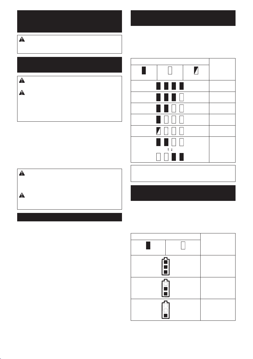
NOTE:WhentheLEDdisplaygoesoff,thetoolis
turnedofftosavethebatterypower.Tocheckthe
remaining battery capacity, slightly pull the switch
trigger.
NOTE:TheLEDdisplaygoesoffapproximatelyone
minute after releasing the switch trigger.
NOTE:WhentheLEDdisplaylightsupandthetool
stops even with a recharged battery cartridge, cool
down the tool fully. If the status will not change, stop
using and have the tool repaired by a Makita local
service center.
NOTE:Whenthetoolisoverheated,thelightashes
foroneminute,andthentheLEDdisplaygoesoff.In
this case, cool down the tool before operating again.
Switch action
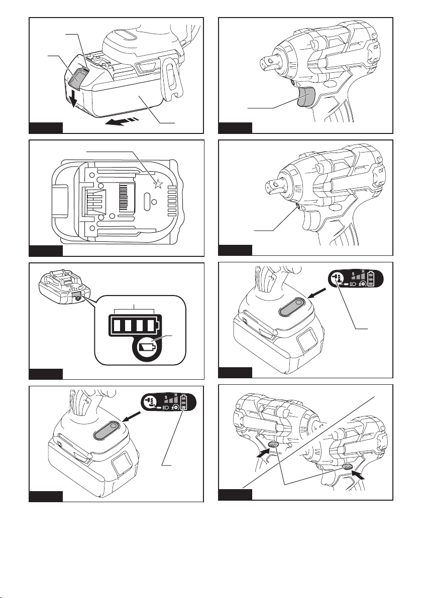
►Fig.5: 1. Switch trigger
CAUTION: Before installing the battery car-
tridge into the tool, always check to see that the
switch trigger actuates properly and returns to
the "OFF" position when released.
Tostartthetool,simplypulltheswitchtrigger.Tool
speed is increased by increasing pressure on the switch
trigger. Release the switch trigger to stop.
NOTE:Thetoolautomaticallystopswhenyoukeep
pulling the switch trigger for 3 minutes.
Lighting up the front lamp
CAUTION: Do not look in the light or see the
source of light directly.
►Fig.6: 1. Lamp
►Fig.7: 1. Button
Toturnonthelampstatus,pressthebutton for
onesecond.Toturnoffthelampstatus,pressthebut-
ton for one second again.
WiththelampstatusON,pulltheswitchtriggertoturnon
thelamp.Toturnoff,releaseit.Thelampgoesoutapprox-
imately 10 seconds after releasing the switch trigger.
WiththelampstatusOFF,thelampdoesnotturnon
even if pulling the trigger.
NOTE:Toconrmthelampstatus,pullthetrigger.
Whenthelamplightsupbypullingtheswitchtrigger,
thelampstatusisON.Whenthelampdoesnotcome
on, the lamp status is OFF.
NOTE: Use a dry cloth to wipe the dirt off the lens of
the lamp. Be careful not to scratch the lens of lamp, or
it may lower the illumination.
NOTE:Whilepullingtheswitchtrigger,thelamp
status cannot be changed.
NOTE:Forapproximately10secondsafterreleasing
the switch trigger, the lamp status can be changed.
Reversing switch action
►Fig.8: 1. Reversing switch lever
CAUTION: Always check the direction of
rotation before operation.
CAUTION:
Use the reversing switch only after
the tool comes to a complete stop. Changing the direc-
tion of rotation before the tool stops may damage the tool.
CAUTION:
When not operating the tool, always
set the reversing switch lever to the neutral position.
Thistoolhasareversingswitchtochangethedirection
of rotation. Depress the reversing switch lever from the
AsideforclockwiserotationorfromtheBsideforcoun-
terclockwise rotation.
Whenthereversingswitchleverisintheneutralposi-
tion, the switch trigger cannot be pulled.
Changing the impact force/mode
►Fig.9: 1. Changed in four steps 2. Hard impact
mode 3. Medium impact mode 4. Soft impact
mode 5. Reverse rotation auto stop mode
6. Button
Youcanchangetheimpactmodeinfoursteps:hard,
medium, soft, and reverse rotation auto stop mode.
Toselectthestep,pressthebutton .
Forapproximatelyoneminuteafterreleasingtheswitch
trigger, the impact force can be changed.
Hard, Medium, and Soft impact mode allows a tighten-
ing suitable to the work.
Thefunctionofreverserotationautostopmodeworks
only with pulling the trigger fully in counterclockwise tool
rotation.Whenthebolt/nutgetsenoughloosened,the
tool stops the impact and rotation.
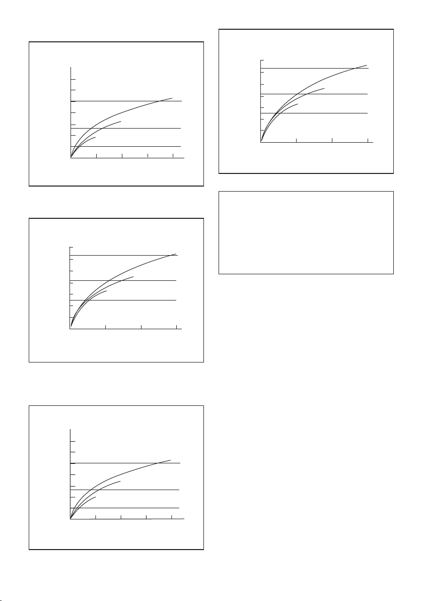
Specications of each impact force grade
Impact force grade displayed
on panel
Maximum blows Application Work
Hard 3,500 min-1(/min) Tighteningwhenforceand
speed are desired.
Assemblingthesteelframe.
Medium 2,600 min-1(/min) Tighteningwhenyouneed
good controlled power.
Assemblingordisassembling
scaffolds or framework.

8ENGLISH
Impact force grade displayed
on panel
Maximum blows Application Work
Soft 1,800 min-1(/min) Tighteningwhenyouneedne
adjustmentwithsmalldiameter
bolt.
Assemblingfurnitures.
Reverse rotation auto stop
mode
3,500 min-1(/min) Loosening with auto stop
function.
Disassemblingbolts/nuts.
NOTE:Reverserotationautostopmodeisavailableonlywhenthetoolrotatescounterclockwise.Whenrotating
clockwise in reverse rotation auto stop mode, the impact force and speed are the same as Hard impact mode.
ASSEMBLY
CAUTION: Always be sure that the tool is
switched off and the battery cartridge is removed
before carrying out any work on the tool.
Selecting correct impact socket
Alwaysusethecorrectsizeimpactsocketforboltsand
nuts.Anincorrectsizeimpactsocketwillresultininac-
curateandinconsistentfasteningtorqueand/ordamage
to the bolt or nut.
Installing or removing impact socket
CAUTION: Make sure that the impact socket
and the mounting portion are not damaged before
installing the impact socket.
CAUTION: After inserting the impact socket,
make sure that it is rmly secured. If it comes out,
do not use it.
For impact socket without O-ring
and pin
►Fig.10: 1. Impact socket 2. Square drive
Aligntheholeinthesideoftheimpactsocketwiththe
detent pin on the square drive and push the impact
socketontothesquaredriveuntilitlocksintoplace.Tap
it lightly if required.
Toremovetheimpactsocket,simplypullitoff.
For impact socket with O-ring
and pin
►Fig.11: 1. Impact socket 2. O-ring 3.Pin
Move the O-ring out of the groove in the impact socket
and remove the pin from the impact socket. Fit the impact
socket onto the square drive so that the hole in the impact
socket is aligned with the hole in the square drive.
Insert the pin through the hole in the impact socket and
squaredrive.ThenreturntheO-ringtotheoriginalposi-
tion in the impact socket groove to retain the pin.
Toremovetheimpactsocket,followtheinstallation
procedures in reverse.
Installing hook
►Fig.12: 1. Groove 2. Hook 3. Screw
Thehookisconvenientfortemporarilyhangingthetool.
Thiscanbeinstalledoneithersideofthetool.Toinstall
the hook, insert it into a groove in the tool housing on
eithersideandthensecureitwithascrew.Toremove,
loosen the screw and then take it out.
OPERATION
CAUTION: Always insert the battery cartridge
all the way until it locks in place. If you can see the
red indicator on the upper side of the button, it is not
locked completely. Insert it fully until the red indicator
cannot be seen. If not, it may accidentally fall out of
thetool,causinginjurytoyouorsomeonearound
you.
►Fig.13
Holdthetoolrmlyandplacetheimpactsocketover
theboltornut.Turnthetoolonandfastenfortheproper
fastening time.
Theproperfasteningtorquemaydifferdependingupon
thekindorsizeofthebolt,thematerialoftheworkpiece
tobefastened,etc.Therelationbetweenfastening
torqueandfasteningtimeisshowninthegures.

9ENGLISH
Model DTW284
Proper fastening torque for standard bolt
0
M20
M16
M16
M20
M12
M12
12
280
240
200
160
120
80
40
1
2
N•m
1. Fastening time (second) 2. Fastening torque
Proper fastening torque for high tensile bolt
123
280
240
200
160
120
80
40
1
2
N•m
0
M12H
M14H
M16H
M12H
M14H
M16H
1. Fastening time (second) 2. Fastening torque
Model DTW285
Proper fastening torque for standard bolt
0
M20
M16
M16
M20
M12
M12
12
280
240
200
160
120
80
40
1
2
N•m
1. Fastening time (second) 2. Fastening torque
Proper fastening torque for high tensile bolt
0
160
120
80
40
200
23
1
M12H
280
240
M14H
M16H
M12H
M14H
M16H
1
2
N•m
1. Fastening time (second) 2. Fastening torque
NOTE: Hold the tool pointed straight at the bolt or nut.
NOTE:Excessivefasteningtorquemaydamagethe
bolt/nutorimpactsocket.Beforestartingyourjob,
always perform a test operation to determine the
proper fastening time for your bolt or nut.
NOTE: If the tool is operated continuously until the
battery cartridge has discharged, allow the tool to rest
for 15 minutes before proceeding with a fresh battery
cartridge.
Thefasteningtorqueisaffectedbyawidevarietyof
factorsincludingthefollowing.Afterfastening,always
check the torque with a torque wrench.
1. Whenthebatterycartridgeisdischargedalmost
completely, voltage will drop and the fastening
torque will be reduced.
2. Impact socket
• Failuretousethecorrectsizeimpactsocket
will cause a reduction in the fastening torque.
• Awornimpactsocket(wearonthehexend
or square end) will cause a reduction in the
fastening torque.
3. Bolt
• Eventhoughthetorquecoefcientandthe
class of bolt are the same, the proper fasten-
ing torque will differ according to the diame-
ter of bolt.
• Eventhoughthediametersofboltsarethe
same, the proper fastening torque will differ
accordingtothetorquecoefcient,theclass
of bolt and the bolt length.
4. Theuseoftheuniversaljointortheextension
bar somewhat reduces the fastening force of the
impact wrench. Compensate by fastening for a
longer period of time.
5. Themannerofholdingthetoolorthematerial
of driving position to be fastened will affect the
torque.
6. Operating the tool at low speed will cause a reduc-
tion in the fastening torque.

10 ENGLISH
MAINTENANCE
CAUTION: Always be sure that the tool is
switched off and the battery cartridge is removed
before attempting to perform inspection or
maintenance.
NOTICE: Never use gasoline, benzine, thinner,
alcohol or the like. Discoloration, deformation or
cracks may result.
TomaintainproductSAFETYandRELIABILITY,
repairs,anyothermaintenanceoradjustmentshould
beperformedbyMakitaAuthorizedorFactoryService
Centers, always using Makita replacement parts.
OPTIONAL
ACCESSORIES
CAUTION: These accessories or attachments
are recommended for use with your Makita tool
specied in this manual.Theuseofanyother
accessories or attachments might present a risk of
injurytopersons.Onlyuseaccessoryorattachment
for its stated purpose.
If you need any assistance for more details regard-
ing these accessories, ask your local Makita Service
Center.
• Impactsocket
• Extensionbar
• Universaljoint
• Socketbitadapter
• Makitagenuinebatteryandcharger
NOTE: Some items in the list may be included in the
toolpackageasstandardaccessories.Theymay
differ from country to country.

11 FRANÇAIS
FRANÇAIS (Instructions originales)
SPÉCIFICATIONS
Modèle : DTW284 DTW285
Capacités de serrage Boulon standard M10 - M20
Boulon à haute
résistance
M10 - M16
Carré conducteur 12,7 mm
Vitesse à vide Mode de percussion
rude
0 - 2 800 min-1
Mode de percussion
moyenne
0 - 2 100 min-1
Mode de percussion
douce
0 - 1 600 min-1
Coups par minute Mode de percussion
rude
0 - 3 500 min-1
Mode de percussion
moyenne
0 - 2 600 min-1
Mode de percussion
douce
0 - 1 800 min-1
Longueur totale 147 mm
Tensionnominale 14,4 V CC 18 V CC
Batterie BL1415, BL1415N BL1430, BL1430B,
BL1440, BL1450,
BL1460B
BL1815, BL1815N,
BL1820, BL1820B
BL1830, BL1830B,
BL1840, BL1840B,
BL1850, BL1850B,
BL1860B
Poidsnet 1,4 kg 1,6 kg 1,5 kg 1,7 kg
• Étantdonnél’évolutionconstantedenotreprogrammederechercheetdedéveloppement,lesspécications
contenuesdanscemanuelsontsujettesàmodicationsanspréavis.
• Lesspécicationsetlabatteriepeuventêtredifférentessuivantlespays.
• Poids,aveclabatterie,conformémentàlaprocédureEPTA-01/2003
Utilisations
L’outilestconçupourlaxationdesboulonsetdes
écrous.
Bruit
NiveaudebruitpondéréAtypique,déterminéselon
EN60745:
Niveau de pression sonore (LpA):96dB(A)
Niveau de puissance sonore (LWA):107dB(A)
Incertitude(K):3dB(A)
AVERTISSEMENT : Portez un serre-tête
antibruit.
Vibrations
Valeurtotaledevibrations(sommedevecteurtriaxial)
déterminéeselonEN60745:
Modèle DTW284
Modedetravail:serrageavecimpactdevisouboulon
nedépassantpaslacapacitémaximaledel’outil
Émissiondevibrations(ah):14,0m/s2
Incertitude(K):1,5m/s2
Modèle DTW285
Modedetravail:serrageavecimpactdevisouboulon
nedépassantpaslacapacitémaximaledel’outil
Émissiondevibrations(ah):11,5m/s2
Incertitude(K):1,5m/s2
NOTE :Lavaleurd’émissiondevibrationsdéclarée
a été mesurée conformément à la méthode de test
standardetpeutêtreutiliséepourcomparerlesoutils
entreeux.
NOTE :Lavaleurd’émissiondevibrationsdéclarée
peutaussiêtreutiliséepourl’évaluationpréliminaire
del’exposition.
AVERTISSEMENT :L’émissiondevibrations
lorsdel’usageréeldel’outilélectriquepeutêtre
différentedelavaleurd’émissiondéclarée,suivantla
façondontl’outilestutilisé.
AVERTISSEMENT : Les mesures de sécurité à
prendrepourprotégerl’utilisateurdoiventêtrebasées
suruneestimationdel’expositiondansdescondi-
tionsréellesd’utilisation(entenantcomptedetoutes
lescomposantesducycled’utilisation,commepar
exemplelemomentdesamisehorstension,lorsqu’il
tourne à vide et le moment de son déclenchement).

12 FRANÇAIS
Déclaration de conformité CE
Pour les pays européens uniquement
LadéclarationdeconformitéCEestfournieenAnnexe
Aàcemoded’emploi.
CONSIGNES DE
SÉCURITÉ
Consignes de sécurité générales
pour outils électriques
AVERTISSEMENT : Lisez toutes les
consignes de sécurité et toutes les instructions. Il
yarisqued’électrocution,d’incendieet/oudegraves
blessures si les mises en garde et les instructions ne
sont pas respectées.
Conservez toutes les mises en
garde et instructions pour réfé-
rence ultérieure.
Le terme « outil électrique » dans les avertissements
faitréférenceàl’outilélectriquealimentéparlesecteur
(aveccordond’alimentation)ouàl’outilélectriquefonc-
tionnantsurbatterie(sanscordond’alimentation).
Consignes de sécurité pour
boulonneuse sans l
1. Tenez l’outil électrique par des surfaces de
prise isolées lorsque vous effectuez une tâche
au cours de laquelle la vis ou le boulon peut
entrer en contact avec des ls cachés. Le
contactdelavisouduboulonavecunlsousten-
sion peut transmettre du courant dans les pièces
métalliquesexposéesdel’outiletélectrocuter
l’opérateur.
2. Portez un casque anti-bruit.
3. Vériez que la douille à choc n’est pas usée,
ssurée ou endommagée avant l’installation.
4. Tenez votre outil fermement.
5. Gardez les mains éloignées des pièces en
rotation.
6. Ayez toujours une assise ferme sous vos
pieds.
Veillez à ce que personne ne se trouve en
dessous de vous quand vous utilisez l’outil en
hauteur.
7. Le couple de serrage correct peut varier
en fonction du type ou de la dimension du
boulon. Vériez le couple à l’aide d’une clé
dynamométrique.
CONSERVEZ CES
INSTRUCTIONS.
AVERTISSEMENT : NE vous laissez PAS
tromper (au l d’une utilisation répétée) par un
sentiment d’aisance et de familiarité avec le
produit, en négligeant le respect rigoureux des
consignes de sécurité qui accompagnent le pro-
duit en question.
La MAUVAISE UTILISATION de l’outil ou l’igno-
rance des consignes de sécurité indiquées
dans ce mode d’emploi peut entraîner de graves
blessures.
Consignes de sécurité importantes
pour la batterie
1. Avant d’utiliser la batterie, lisez toutes les
instructions et précautions relatives (1) au
chargeur de batterie, (2) à la batterie, et (3) au
produit utilisant la batterie.
2. Ne démontez pas la batterie.
3. Cessez immédiatement l’utilisation si le temps
de fonctionnement devient excessivement
court. Il y a risque de surchauffe, de brûlures,
voire d’explosion.
4.
Si l’électrolyte pénètre dans vos yeux, rincez-les
à l’eau claire et consultez immédiatement un
médecin. Il y a risque de perte de la vue.
5. Ne court-circuitez pas la batterie :
(1) Ne touchez les bornes avec aucun maté-
riau conducteur.
(2) Évitez de ranger la batterie dans un
conteneur avec d’autres objets métal-
liques, par exemple des clous, des pièces
de monnaie, etc.
(3) N’exposez pas la batterie à l’eau ou à la
pluie.
Un court-circuit de la batterie peut provoquer
une intensité de courant élevée, une surchauffe,
parfois des brûlures et même une panne.
6. Ne rangez pas l’outil et la batterie dans un
endroit où la température risque d’atteindre ou
de dépasser 50 °C.
7.
Ne jetez pas la batterie au feu même si elle est
sérieusement endommagée ou complètement épui-
sée. La batterie peut exploser au contact du feu.
8.
Évitez de laisser tomber ou de cogner la batterie.
9. N’utilisez pas la batterie si elle est
endommagée.
10. Les batteries au lithium-ion contenues sont
soumises aux exigences de la législation sur
les marchandises dangereuses.
Lors du transport commercial par des tierces
partiesoudestransitairesparexemple,desexi-
gencesspéciquesenmatièred’étiquetageet
d’emballagedoiventêtrerespectées.
Pourlapréparationdel’articleexpédié,ilest
nécessairedeconsulterunexpertenmatériau
dangereux.Veuillezégalementrespecterles
réglementationsnationalessusceptiblesd’être
plus détaillées.
Recouvrezlescontactsexposésavecduruban
adhésifoudurubandemasquageetemballezla
batteriedetellesortequ’ellenepuissepasbouger
dansl’emballage.

13 FRANÇAIS
11. Suivez les réglementations locales en matière
de mise au rebut des batteries.
CONSERVEZ CES
INSTRUCTIONS.
ATTENTION : N’utilisez que des batteries
Makita d’origine.L’utilisationdebatteriesdemarque
autrequeMakitaoudebatteriesmodiéespeutpro-
voquerl’explosiondesbatteries,cequiprésenteun
risqued’incendie,dedommagesmatérielsetcorpo-
rels. Cela annulera également la garantie Makita pour
l’outiletlechargeurMakita.
Conseils pour assurer la durée
de vie optimale de la batterie
1. Chargez la batterie avant qu’elle ne soit com-
plètement déchargée. Arrêtez toujours l’outil
et rechargez la batterie quand vous remarquez
que la puissance de l’outil diminue.
2. Ne rechargez jamais une batterie complète-
ment chargée. La surcharge réduit la durée de
service de la batterie.
3. Chargez la batterie à une température
ambiante comprise entre 10 °C et 40 °C. Avant
de charger une batterie chaude, laissez-la
refroidir.
4. Rechargez la batterie si elle est restée inutili-
sée pendant une période prolongée (plus de
six mois).
DESCRIPTION DU
FONCTIONNEMENT
ATTENTION : Assurez-vous toujours que
l’outil est hors tension et que sa batterie est
retirée avant de l’ajuster ou de vérier son
fonctionnement.
Insertion ou retrait de la batterie
ATTENTION : Éteignez toujours l’outil avant
de mettre en place ou de retirer la batterie.
ATTENTION : Tenez fermement l’outil et la
batterie lors de la mise en place ou du retrait de
la batterie.Sivousnetenezpasfermementl’outil
et la batterie, ils peuvent vous glisser des mains, et
s’abîmerouvousblesser.
►Fig.1: 1. Voyant rouge 2. Bouton 3. Batterie
Pourretirerlabatterie,faites-laglisserhorsdel’outil
toutenfaisantglisserleboutonàl’avantdelabatterie.
Pourmettreenplacelabatterie,alignezlalanguettesur
la batterie avec la rainure sur le compartiment et insé-
rez-la.Insérez-laàfondjusqu’àcequ’unlégerdéclic
se fasse entendre. Si le voyant rouge sur le dessus du
boutonestvisible,celasigniequ’ellen’estpasbien
verrouillée.
ATTENTION : Insérez toujours complètement
la batterie jusqu’à ce que le voyant rouge ne soit
plus visible. Sinon, elle pourrait tomber acciden-
tellementdel’outil,aurisquedevousblesseroude
blesserquelqu’unsetrouvantprèsdevous.
ATTENTION : N’insérez pas la batterie de
force.Sielleneglissepasfacilement,c’estquevous
nel’insérezpascorrectement.
Système de protection de la batterie
Batterie au lithium-ion avec repère étoilé
►Fig.2: 1. Repère étoilé
Les batteries au lithium-ion avec un repère étoilé sont
pourvuesd’unsystèmedeprotection.Cesystème
coupeautomatiquementl’alimentationversl’outilpour
prolongerl’autonomiedelabatterie.
L’outils’arrêteraautomatiquementencoursd’utilisation
sil’outilet/oulabatteriesetrouvedansl’uneoul’autre
dessituationssuivantes:
Surcharge :
L’outilestutilisédemanièretellequ’ilconsommeun
courant anormalement élevé.
Danscecas,éteignezl’outiletarrêtezlatâcheayant
provoquélasurchargedel’outil.Puisrallumezl’outil
pourreprendrelatâche.
Sil’outilnedémarrepas,c’estquelabatterieasur-
chauffé.Danscecas,laissezlabatterierefroidiravant
derallumerl’outil.
Faible tension de la batterie :
Lacapacitérestantedelabatterieesttropfaibleetl’outilne
fonctionnepas.Lecaséchéant,retirezetrechargezlabatterie.
Indication de la charge restante de
la batterie
Uniquement pour les batteries avec voyant
lumineux
►Fig.3: 1.Témoins2.Boutondevérication
Appuyezsurleboutondevéricationsurlabatterie
pour indiquer la charge restante de la batterie. Les
témoinss’allumentpendantquelquessecondes.
Témoins Charge
restante
Allumé Éteint Clignotant
75 % à 100 %
50 % à 75 %
25 % à 50 %
0 % à 25 %
Chargezla
batterie.
Anomalie
possible
de la batterie.

14 FRANÇAIS
NOTE :Selonlesconditionsd’utilisationetlatem-
pératureambiante,l’indicationpeutêtrelégèrement
différente de la capacité réelle.
Indication de la charge restante de
la batterie
Propre au pays
►Fig.4: 1.Témoindelabatterie
Lorsquevousenclenchezlagâchette,l’afchageDEL
indique la charge restante de la batterie. La charge
restante de la batterie est indiquée conformément au
tableau ci-dessous.
Statut du témoin de la batterie Charge restante
de la batterie
Allumé Éteint
50 % à 100 %
20 % à 50 %
0 % à 20 %
NOTE :Lorsquel’afchageDELs’éteint,l’outilest
mishorstensionpouréconomiserlabatterie.Pour
vérierlachargerestantedelabatterie,enclenchez
légèrementlagâchette.
NOTE :L’afchageDELs’éteintenvironuneminute
aprèsavoirrelâchélagâchette.
NOTE :Sil’afchageDELs’allumeetquel’outil
s’arrêtealorsquelabatterieestrechargée,laissez
refroidircomplètementl’outil.Silestatutnechange
pas,cessezd’utiliserl’outiletconezsaréparationà
un centre de service après-vente local Makita.
NOTE :Encasdesurchauffedel’outil,lalumière
clignotependantuneminute,puisl’afcheuràDEL
s’éteint.Ilfautalorslaisserrefroidirl’outilavantdele
remettre en marche.
Fonctionnement de la gâchette
►Fig.5: 1.Gâchette
ATTENTION : Avant d’insérer la batterie dans
l’outil, vériez toujours que la gâchette fonc-
tionne bien et revient en position d’arrêt lorsque
vous la relâchez.
Ilsuftd’enclencherlagâchettepourdémarrerl’outil.
Lavitessedel’outilaugmenteàmesurequel’onaccroît
lapressionexercéesurlagâchette.Pourl’arrêter,
relâchezlagâchette.
NOTE :L’outils’arrêteautomatiquementlorsque
vouscontinuezd’enclencherlagâchettependant3
minutes.
Allumage de la lampe avant
ATTENTION : Évitez de regarder directement
le faisceau lumineux ou sa source.
►Fig.6: 1. Lampe
►Fig.7: 1. Bouton
Pouractiverlalampe,appuyezsurlebouton pen-
dantuneseconde.Pourdésactiverlalampe,appuyezà
nouveau sur le bouton pendant une seconde.
Aveclalampeactivée,enclenchezlagâchettepour
allumerlalampe.Pouréteindrelalampe,libérezla
gâchette.Lalampes’éteintauboutde10secondes
environaprèsavoirrelâchélagâchette.
Lorsquelalampeestdésactivée,ellenes’allumepas
mêmesivousenclenchezlagâchette.
NOTE :Pourvériersilalampeestactivéeoudésac-
tivée,enclenchezlagâchette.Silalampes’allume
lorsquevousenclenchezlagâchette,celasignie
qu’elleestactivée.Silalampenes’allumepas,cela
signiequ’elleestdésactivée.
NOTE :Retirezlasaletésurlalentilledelalampe
avecunchiffonsec.Prenezsoindenepaséraer
la lentille de la lampe sous peine de diminuer son
éclairage.
NOTE :Iln’estpaspossibled’activeroudedésacti-
verlalampependantquelagâchetteestenclenchée.
NOTE :Ilestpossibled’activeroudedésactiverla
lampe pendant environ 10 secondes après avoir
relâchélagâchette.
Fonctionnement de l’inverseur
►Fig.8: 1.Levierdel’inverseur
ATTENTION : Vériez toujours le sens de
rotation avant d’utiliser l’outil.
ATTENTION : N’utilisez l’inverseur qu’une
fois que l’outil est complètement arrêté. Si vous
changezlesensderotationavantl’arrêtdel’outil,
vousrisquezdel’endommager.
ATTENTION : Lorsque vous n’utilisez pas
l’outil, placez toujours le levier de l’inverseur en
position neutre.
L’outilpossèdeuninverseurquipermetdechanger
lesensderotation.Enfoncezlelevierdel’inverseur
ducôtéApourunerotationdanslesensdesaiguilles
d’unemontre,ouducôtéBpourunerotationdansle
sensinversedesaiguillesd’unemontre.
Lagâchettenepeutpasêtreenclenchéelorsquele
levierdel’inverseursetrouveenpositionneutre.

15 FRANÇAIS
Changement de la force ou du mode de percussion
►Fig.9: 1.Modicationselonquatreniveaux2. Mode
de percussion puissant 3. Mode de percus-
sion moyenne 4. Mode de percussion faible
5.Moded’arrêtautomatiqueenrotation
arrière 6. Bouton
Vouspouvezmodierlemodedepercussionselon
quatreniveaux:puissant,moyen,faibleetmoded’arrêt
automatique en rotation arrière.
Poursélectionnerleniveau,appuyezsurlebouton .
Laforceduchocestmodiablependantenvironune
minuteaprèsavoirrelâchélagâchette.
Les modes de percussion puissant, moyen et faible
vouspermettentd’obtenirunserrageadaptéautype
de travail.
Lemoded’arrêtautomatiqueenrotationarrièrefonc-
tionneuniquementsivousenclenchezàfondlagâchette
avecl’outiltournantdanslesensinversedesaiguilles
d’unemontre.Unefoisqueleboulonoul’écrouest
assezdesserré,l’outilarrêtelapercussionetlarotation.
Spécications de la gradation de la force du choc
Gradation de la force du choc
afchée sur le panneau
Frappes maximum Application Tâche
Puissant 3 500 min-1 Serragelorsqueletravailexige
force et vitesse.
Assemblagedechâssisd’acier.
Moyen 2 600 min-1 Serrage lorsque le travail
exigeunboncontrôledela
puissance.
Assemblageoudésassem-
blaged’échafaudagesoude
charpente.
Faible 1 800 min-1 Serragelorsqueletravailexige
unréglagenavecunboulon
de petit diamètre.
Assemblagedemeubles.
Moded’arrêtautomatiqueen
rotation arrière
3 500 min-1 Desserrage avec fonction
d’arrêtautomatique.
Désassemblage de boulons
ou écrous.
NOTE :Lemoded’arrêtautomatiqueenrotationarrièren’estdisponiblequelorsquel’outiltournedanslesens
inversedesaiguillesd’unemontre.Sil’outiltournedanslesensdesaiguillesd’unemontreenmoded’arrêtauto-
matique en rotation arrière, la force de percussion et la vitesse seront identiques à celles du mode de percussion
puissant.
ASSEMBLAGE
ATTENTION : Assurez-vous toujours que
l’outil est hors tension et que sa batterie est reti-
rée avant d’effectuer toute tâche dessus.
Sélection de la bonne douille à choc
Utiliseztoujoursunedouilleàchocdetaillecorrecte
pour les boulons et les écrous. Une douille à choc de
tailleincorrecteentraînerauncoupledeserrageimpré-
cisetinégalet/ouendommageraleboulonoul’écrou.
Pose ou dépose de la douille à choc
ATTENTION : Assurez-vous que la douille
à choc et la section de montage ne sont pas
endommagées avant de poser la douille à choc.
ATTENTION : Après avoir inséré la douille à
choc, assurez-vous qu’elle est fermement xée.
Si vous arrivez à la retirer, ne l’utilisez pas.
Pour les douilles à choc sans joint
torique et tige
►Fig.10: 1. Douille à choc 2. Carré conducteur
Alignezl’oricesurlecôtédeladouilleàchocsurla
goupilled’arrêtducarréconducteuretenfoncezla
douilleàchocdanslecarréconducteurjusqu’àce
qu’elleseverrouilleenplace.Tapezlégèrementdessus
si nécessaire.
Pourretirerladouilleàchoc,tirezsimplementdessus.

16 FRANÇAIS
Pour les douilles à choc avec joint
torique et tige
►Fig.11: 1. Douille à choc 2. Joint torique 3.Tige
Retirezlejointtoriquedelarainuredeladouilleàchoc
etretirezlatigedeladouilleàchoc.Placezladouille
à choc sur le carré conducteur en alignant le trou de la
douille à choc avec celui du carré conducteur.
Insérezlatigedanslestrousalignésdeladouilleàchocetdu
carréconducteur.Puis,ramenezlejointtoriqueàsapositiond’ori-
gine dans la rainure de la douille à choc pour verrouiller la tige.
Pourretirerladouilleàchoc,procédezdansl’ordre
inversedel’installation.
Installation du crochet
►Fig.12: 1. Rainure 2. Crochet 3. Vis
L’outilestéquipéd’uncrochetpratiquequipermetdel’accrocher
temporairement.Cecrochets’installed’uncôtécommedel’autre
del’outil.Pourinstallerlecrochet,insérez-ledansunedesrai-
nuressituéesdechaquecôtéducarterdel’outil,puisserrez-le
avecdeuxvis.Pourl’enlever,desserrezlesvisetretirez-le.
UTILISATION
ATTENTION :
Insérez toujours la batterie à fond
jusqu’à ce qu’elle se verrouille en place. Si le voyant rouge
surledessusduboutonestvisible,celasigniequ’ellen’est
pasbienverrouillée.Insérez-lacomplètementjusqu’àceque
le voyant rouge ne soit plus visible. Sinon, elle pourrait tom-
beraccidentellementdel’outil,aurisquedevousblesserou
deblesserquelqu’unsetrouvantprèsdevous.
►Fig.13
Tenezl’outilfermementetplacezladouilleàchocsur
leboulonoul’écrou.Mettezl’outilenmarcheetserrez
pendant la durée de serrage appropriée.
Le couple de serrage correct peut varier en fonction du
type ou de la dimension du boulon, du matériau de la
pièceàxer,etc.Lerapportentrelecoupledeserrage
etladuréedeserrageestindiquédanslesgures.
Modèle DTW284
Couple de serrage correct pour boulon standard
0
M20
M16
M16
M20
M12
M12
12
280
240
200
160
120
80
40
1
2
N•m
1. Durée de serrage (en secondes) 2. Couple de serrage
Couple de serrage correct pour boulon à haute
résistance
123
280
240
200
160
120
80
40
1
2
N•m
0
M12H
M14H
M16H
M12H
M14H
M16H
1. Durée de serrage (en secondes) 2. Couple de serrage
Modèle DTW285
Couple de serrage correct pour boulon standard
0
M20
M16
M16
M20
M12
M12
12
280
240
200
160
120
80
40
1
2
N•m
1. Durée de serrage (en secondes) 2. Couple de serrage
Couple de serrage correct pour boulon à haute
résistance
0
160
120
80
40
200
23
1
M12H
280
240
M14H
M16H
M12H
M14H
M16H
1
2
N•m
1. Durée de serrage (en secondes) 2. Couple de serrage

17 FRANÇAIS
NOTE :Tenezl’outildesortequ’ilpointebiendroit
versleboulonoul’écrou.
NOTE :Uncoupledeserrageexcessifpeutabîmer
leboulon,l’écrououladouilleàchoc.Avantde
commencerletravail,effectueztoujoursuntestpour
connaîtreladuréedeserrageadéquatepourlebou-
lonoul’écrou.
NOTE :Sil’outilfonctionnedefaçoncontinuejusqu’à
ce que la batterie soit complètement déchargée,
laissez-lereposerpendant15minutesavantde
poursuivreletravailavecunebatteriefraîchement
rechargée.
Lecoupledeserragedépendd’uncertainnombrede
facteurs, comme suit. Une fois le serrage terminé, véri-
eztoujourslecoupleavecuneclédynamométrique.
1. Lorsque la batterie est presque complètement
déchargée, la tension tombe et le couple de ser-
rage diminue.
2. Douille à choc
• L’utilisationd’unedouilleàchocdetaille
incorrecteentraînerauneréductiondu
couple de serrage.
• Unedouilleàchocusée(usuresurl’extré-
mitéhexagonaleousurl’extrémitécarrée)
entraînerauneréductionducouplede
serrage.
3. Boulon
• Mêmesilecoefcientducoupleetlacaté-
gorieduboulonsontlesmêmes,lecouple
de serrage correct variera en fonction du
diamètre de boulon.
•
Mêmesilesdiamètresdesboulonssontles
mêmes,lecoupledeserragecorrectvarieraen
fonctionducoefcientdecouple,delacatégo-
rie du boulon et de la longueur du boulon.
4. L’utilisationd’unjointuniverseloud’unebarrede
rallonge réduit quelque peu la force de serrage
delaboulonneuse.Compensezenserrantplus
longtemps.
5. Lecoupledeserrageestaffectéparlafaçondont
voustenezl’outiloulapièce,ouparlapositionde
vissage.
6. Lefonctionnementdel’outilàvitesseréduite
entraîneunediminutionducoupledeserrage.
ENTRETIEN
ATTENTION : Assurez-vous toujours que
l’outil est hors tension et que la batterie est reti-
rée avant d’y effectuer tout travail d’inspection ou
d’entretien.
REMARQUE : N’utilisez jamais d’essence, ben-
zine, diluant, alcool ou autre produit similaire.
Cela risquerait de provoquer la décoloration, la
déformation ou la ssuration de l’outil.
PourassurerlaSÉCURITÉetlaFIABILITÉduproduit,
touteréparation,touttravaild’entretienouderéglage
doiventêtreeffectuésparuncentred’entretienMakita
agréé, avec des pièces de rechange Makita.
ACCESSOIRES EN
OPTION
ATTENTION : Ces accessoires ou pièces
complémentaires sont recommandés pour l’utili-
sation avec l’outil Makita spécié dans ce mode
d’emploi.L’utilisationdetoutautreaccessoireou
pièce complémentaire peut comporter un risque de
blessure.N’utilisezlesaccessoiresoupiècescomplé-
mentairesqu’auxnsauxquellesilsontétéconçus.
Pourobtenirplusdedétailssurcesaccessoires,
contactezvotrecentred’entretienlocalMakita.
• Douilleàchoc
• Barrederallonge
• Jointuniversel
• Adaptateurpouremboutàdouille
• BatterieetchargeurMakitad’origine
NOTE : Il se peut que certains éléments de la liste
soientcomprisdansl’emballagedel’outilentant
qu’accessoiresstandard.Ilspeuventvarierd’unpays
àl’autre.

18 DEUTSCH
DEUTSCH (Original-Anleitung)
TECHNISCHE DATEN
Modell: DTW284 DTW285
Anzugskapazitäten Standardschraube M10 - M20
HV-Schraube M10 - M16
Antriebsvierkant 12,7 mm
Leerlaufdrehzahl Starker Schlagmodus 0 - 2.800 min-1
Mittlerer Schlagmodus 0 - 2.100 min-1
Schwacher
Schlagmodus
0 - 1.600 min-1
SchlagzahlproMinute Starker Schlagmodus 0 - 3.500 min-1
Mittlerer Schlagmodus 0 - 2.600 min-1
Schwacher
Schlagmodus
0 - 1.800 min-1
Gesamtlänge 147 mm
Nennspannung 14,4 V Gleichstrom 18 V Gleichstrom
Akku BL1415, BL1415N BL1430, BL1430B,
BL1440, BL1450,
BL1460B
BL1815, BL1815N,
BL1820, BL1820B
BL1830, BL1830B,
BL1840, BL1840B,
BL1850, BL1850B,
BL1860B
Nettogewicht 1,4 kg 1,6 kg 1,5 kg 1,7 kg
• Wirbehaltenunsvor,ÄnderungendertechnischenDatenimZugederEntwicklungunddestechnischen
FortschrittsohnevorherigeAnkündigungvorzunehmen.
• DietechnischenDatenundderAkkukönnenvonLandzuLandunterschiedlichsein.
• GewichtmitAkkunachEPTA-Verfahren01/2003
Vorgesehene Verwendung
DasWerkzeugistfürdasAnziehenvonSchraubenund
Muttern vorgesehen.
Geräusch
TypischerA-bewerteterGeräuschpegelermitteltgemäß
EN60745:
Schalldruckpegel (LpA):96dB(A)
Schallleistungspegel (LWA):107dB(A)
Messunsicherheit(K):3dB(A)
WARNUNG: Einen Gehörschutz tragen.
Schwingungen
Schwingungsgesamtwert(Drei-Achsen-Vektorsumme)
ermitteltgemäßEN60745:
Modell DTW284
Arbeitsmodus:SchlagschraubenvonBefestigungsteilen
dermaximalenKapazitätdesWerkzeugs
Schwingungsemission (ah):14,0m/s2
Messunsicherheit(K):1,5m/s2
Modell DTW285
Arbeitsmodus:SchlagschraubenvonBefestigungsteilen
dermaximalenKapazitätdesWerkzeugs
Schwingungsemission (ah):11,5m/s2
Messunsicherheit(K):1,5m/s2
HINWEIS: Der angegebene
SchwingungsemissionswertwurdeimEinklangmit
derStandardprüfmethodegemessenundkannfür
denVergleichzwischenWerkzeugenherangezogen
werden.
HINWEIS: Der angegebene
Schwingungsemissionswertkannauchfüreine
VorbewertungdesGefährdungsgradsverwendet
werden.
WARNUNG:DieSchwingungsemissionwährend
dertatsächlichenBenutzungdesElektrowerkzeugs
kannjenachderBenutzungsweisedesWerkzeugs
vomangegebenenEmissionswertabweichen.
WARNUNG:IdentizierenSie
SicherheitsmaßnahmenzumSchutzdesBenutzers
anhandeinerSchätzungdesGefährdungsgradsunter
dentatsächlichenBenutzungsbedingungen(unter
BerücksichtigungallerPhasendesArbeitszyklus,wie
z.B.Ausschalt-undLeerlaufzeitendesWerkzeugs
zusätzlichzurBetriebszeit).
EG-Konformitätserklärung
Nur für europäische Länder
DieEG-KonformitätserklärungistalsAnhangAindieser
Bedienungsanleitung enthalten.

19 DEUTSCH
SICHERHEITSWARNUNGEN
Allgemeine Sicherheitswarnungen
für Elektrowerkzeuge
WARNUNG: Lesen Sie alle
Sicherheitswarnungen und Anweisungen durch.
EineMissachtungderuntenaufgeführtenWarnungen
undAnweisungenkannzueinemelektrischen
Schlag,Brandund/oderschwerenVerletzungen
führen.
Bewahren Sie alle Warnungen
und Anweisungen für spätere
Bezugnahme auf.
DerAusdruck„Elektrowerkzeug“indenWarnhinweisen
beziehtsichaufIhrmitNetzstrom(mitKabel)oderAkku
(ohneKabel)betriebenesElektrowerkzeug.
Sicherheitswarnungen für
Akku-Schlagschrauber
1. Halten Sie das Elektrowerkzeug nur an den
isolierten Griffächen, wenn Sie Arbeiten
ausführen, bei denen die Gefahr besteht, dass
das Befestigungselement verborgene Kabel
kontaktiert.BeiKontaktmiteinemStromführen-
denKabelkönnendiefreiliegendenMetallteile
desElektrowerkzeugsebenfallsStromführend
werden,sodassderBenutzereinenelektrischen
Schlag erleiden kann.
2. Tragen Sie Gehörschützer.
3. Überprüfen Sie den
Schlagsteckschlüsseleinsatz vor der
Montage sorgfältig auf Verschleiß, Risse oder
Beschädigung.
4. Halten Sie das Werkzeug mit festem Griff.
5. Halten Sie Ihre Hände von rotierenden Teilen
fern.
6. Achten Sie stets auf sicheren Stand.
Vergewissern Sie sich bei Einsatz des
Werkzeugs an hochgelegenen Arbeitsplätzen,
dass sich keine Personen darunter aufhalten.
7. Das korrekte Anzugsmoment kann je nach Art
oder Größe der Schraube unterschiedlich sein.
Überprüfen Sie das Anzugsmoment mit einem
Drehmomentschlüssel.
DIESE ANWEISUNGEN
AUFBEWAHREN.
WARNUNG: Lassen Sie sich NICHT durch
Bequemlichkeit oder Vertrautheit mit dem Produkt
(durch wiederholten Gebrauch erworben) von der
strikten Einhaltung der Sicherheitsregeln für das
vorliegende Produkt abhalten.
MISSBRAUCH oder Missachtung der
Sicherheitsvorschriften in dieser Anleitung kön-
nen schwere Verletzungen verursachen.
Wichtige Sicherheitsanweisungen
für Akku
1. Lesen Sie vor der Benutzung des Akkus alle
Anweisungen und Warnhinweise, die an (1)
Ladegerät, (2) Akku und (3) Akkuwerkzeug
angebracht sind.
2. Unterlassen Sie ein Zerlegen des Akkus.
3. Falls die Betriebszeit beträchtlich kürzer
geworden ist, stellen Sie den Betrieb sofort
ein. Anderenfalls besteht die Gefahr von
Überhitzung, möglichen Verbrennungen und
sogar einer Explosion.
4. Falls Elektrolyt in Ihre Augen gelangt, waschen
Sie sie mit sauberem Wasser aus, und
begeben Sie sich unverzüglich in ärztliche
Behandlung. Anderenfalls können Sie Ihre
Sehkraft verlieren.
5. Der Akku darf nicht kurzgeschlossen werden:
(1) Die Kontakte dürfen nicht mit leitfähigem
Material berührt werden.
(2) Lagern Sie den Akku nicht in einem
Behälter zusammen mit anderen
Metallgegenständen, wie z. B. Nägel,
Münzen usw.
(3) Setzen Sie den Akku weder Wasser noch
Regen aus.
Ein Kurzschluss des Akkus verursacht star-
ken Stromuss, der Überhitzung, mögliche
Verbrennungen und einen Defekt zur Folge
haben kann.
6. Lagern Sie das Werkzeug und den Akku nicht
an Orten, an denen die Temperatur 50 °C errei-
chen oder überschreiten kann.
7. Versuchen Sie niemals, den Akku zu verbren-
nen, selbst wenn er stark beschädigt oder
vollkommen verbraucht ist. Der Akku kann im
Feuer explodieren.
8. Achten Sie darauf, dass der Akku nicht fallen
gelassen oder Stößen ausgesetzt wird.
9. Benutzen Sie keine beschädigten Akkus.
10. Die enthaltenen Lithium-Ionen-Akkus unter-
liegen den Anforderungen der Gefahrengut-
Gesetzgebung.
FürkommerzielleTransporte,z.B.durch
DritteoderSpediteure,müssenbesondere
AnforderungenzuVerpackungundEtikettierung
beachtet werden.
ZurVorbereitungdeszutransportierenden
ArtikelsisteineBeratungdurcheinenExpertenfür
Gefahrenguterforderlich.BittebeachtenSiemög-
licherweiseausführlicherenationaleVorschriften.
Überkleben oder verdecken Sie offene Kontakte,
undverpackenSiedenAkkuso,dassersichin
der Verpackung nicht umher bewegen kann.
11. Befolgen Sie die örtlichen Bestimmungen
bezüglich der Entsorgung von Akkus.
DIESE ANWEISUNGEN
AUFBEWAHREN.

20 DEUTSCH
VORSICHT: Verwenden Sie nur Original-
Makita-Akkus. Die Verwendung von Nicht-Original-
Makita-AkkusodervonAkkus,dieabgeändert
wordensind,kannzumBerstendesAkkusund
darausresultierendenBränden,Personenschäden
undBeschädigungführen.Außerdemwirddadurch
dieMakita-GarantiefürdasMakita-Werkzeugund
-Ladegerätungültig.
Hinweise zur Aufrechterhaltung
der maximalen
Akku-Nutzungsdauer
1. Laden Sie den Akku, bevor er vollkommen
erschöpft ist. Schalten Sie das Werkzeug stets
aus, und laden Sie den Akku, wenn Sie ein
Nachlassen der Werkzeugleistung feststellen.
2. Unterlassen Sie erneutes Laden eines voll
aufgeladenen Akkus. Überladen führt zu einer
Verkürzung der Nutzungsdauer des Akkus.
3. Laden Sie den Akku bei Raumtemperatur
zwischen 10 – 40 °C. Lassen Sie einen heißen
Akku abkühlen, bevor Sie ihn laden.
4. Der Akku muss geladen werden, wenn er lange
Zeit (länger als sechs Monate) nicht benutzt
wird.
FUNKTIONSBESCHREIBUNG
VORSICHT: Vergewissern Sie sich vor
der Durchführung von Einstellungen oder
Funktionsprüfungen des Werkzeugs stets, dass
das Werkzeug ausgeschaltet und der Akku abge-
nommen ist.
Anbringen und Abnehmen des
Akkus
VORSICHT: Schalten Sie das Werkzeug
stets aus, bevor Sie den Akku anbringen oder
abnehmen.
VORSICHT: Halten Sie das Werkzeug und
den Akku beim Anbringen oder Abnehmen
des Akkus sicher fest.WennSiedasWerkzeug
unddenAkkunichtsicherfesthalten,können
sieIhnenausderHandrutschen,waszueiner
BeschädigungdesWerkzeugsunddesAkkusundzu
Körperverletzungenführenkann.
►Abb.1: 1.RoteAnzeige2. Knopf 3.Akku
ZiehenSiedenAkkuzumAbnehmenvomWerkzeug
ab,währendSiedenKnopfanderVorderseitedes
Akkusverschieben.
RichtenSiezumAnbringendesAkkusdessen
FührungsfederaufdieNutimGehäuseaus,undschie-
benSiedenAkkuhinein.SchiebenSieihnvollständig
ein,bisermiteinemhörbarenKlickeneinrastet.Falls
dieroteAnzeigeanderOberseitedesKnopfessichtbar
ist,istderAkkunichtvollständigverriegelt.
VORSICHT:
Schieben Sie den Akku stets bis
zum Anschlag ein, bis die rote Anzeige nicht mehr
sichtbar ist.AnderenfallskannerausdemWerkzeugher-
ausfallenundSieoderumstehendePersonenverletzen.
VORSICHT: Unterlassen Sie
Gewaltanwendung beim Anbringen des Akkus.
FallsderAkkunichtreibungsloshineingleitet,ister
nicht richtig ausgerichtet.
Akku-Schutzsystem
Lithium-Ionen-Akku mit Sternsymbol
►Abb.2: 1. Sternsymbol
Lithium-Ionen-AkkusmitSternsymbolsindmiteinem
Schutzsystemausgestattet.DiesesSystemschaltetdie
StromversorgungdesWerkzeugsautomatischab,um
dieAkku-Lebensdauerzuverlängern.
DasWerkzeugschaltetsichwährenddesBetriebs
automatischab,wennWerkzeugund/oderAkkueiner
derfolgendenBedingungenunterliegen:
Überlastung:
DasWerkzeugwirdaufeineWeisebenutzt,dieeine
ungewöhnlichhoheStromaufnahmebewirkt.
SchaltenSieindieserSituationdasWerkzeugaus,
undbrechenSiedieArbeitab,dieeineÜberlastung
desWerkzeugsverursachthat.SchaltenSiedanndas
Werkzeugwiederein,umneuzustarten.
FallsdasWerkzeugnichtstartet,istderAkkuüberhitzt.
LassenSiedenAkkuindieserSituationabkühlen,
bevorSiedasWerkzeugwiedereinschalten.
Niedrige Akkuspannung:
DieAkku-Restkapazitätistzuniedrig,unddas
Werkzeugfunktioniertnicht.NehmenSieindieser
SituationdenAkkuab,undladenSieihnauf.
Anzeigen der Akku-Restkapazität
Nur für Akkus mit Anzeige
►Abb.3: 1.Anzeigelampen2.Prüftaste
DrückenSiediePrüftasteamAkku,umdieAkku-
Restkapazitätanzuzeigen.DieAnzeigelampenleuchten
wenige Sekunden lang auf.
Anzeigelampen Restkapazität
Erleuchtet Aus Blinkend
75 % bis
100 %
50% bis 75%
25% bis 50%
0% bis 25%
DenAkku
auaden.
Möglicherweise
liegt eine
Funktionsstörung
imAkkuvor.
This manual suits for next models
2
Table of contents
Languages:
Other Makita Power Tools manuals

Makita
Makita DVR850 User manual

Makita
Makita AN760 User manual

Makita
Makita RP1110 User manual

Makita
Makita JV101D User manual

Makita
Makita DTW190RMJ User manual

Makita
Makita XRH03 User manual

Makita
Makita 3612C User manual

Makita
Makita HM1400 User manual

Makita
Makita 4351FCT Quick start guide

Makita
Makita HXU01 User manual

Makita
Makita HRH01 User manual

Makita
Makita 6933FDWDE User manual

Makita
Makita HR007G User manual

Makita
Makita BST220 User manual

Makita
Makita DTS131 User manual

Makita
Makita 3612 User manual

Makita
Makita 4340CT User manual

Makita
Makita DT 2000 User manual

Makita
Makita M432 Quick start guide

Makita
Makita BHS630 User manual