7ENGLISH
NOTE: When the LED display goes off, the tool is
turned off to save the battery power. To check the
remaining battery c apac ity , sligh tly pull th e sw itc h
trigger.
NOTE: The LED display goes off approximately one
minute af ter releasing th e sw itc h trigger.
NOTE: When the LED display lights up and the tool
stops ev en w ith a rec h arged battery c artrid ge, c ool
d ow n th e tool f ully . I f th e status w ill not c h ange, stop
using and h av e th e tool repaired by a Makita loc al
serv ic e c enter.
NOTE: When the tool is overheated, the light ashes
for one minute, and then the LED display goes off. In
th is c ase, c ool d ow n th e tool bef ore operating again.
Switch action
Fig.5: 1. S w itc h trigger
CAUTION: Before installing the battery car-
tridge into the tool, always check to see that the
switch trigger actuates properly and returns to
the " OFF" position when released.
To start the tool, simply pull the switch trigger. Tool
speed is inc reased by inc reasing pressure on th e sw itc h
trigger. R elease th e sw itc h trigger to stop.
NOTE: The tool automatically stops when you keep
pulling th e sw itc h trigger f or 3 minutes.
Lighting up the front lamp
CAUTION: Do not look in the light or see the
source of light directly.
Fig.6: 1. L amp
Fig.7: 1. Button
To turn on the lamp status, press the button f or
one second. To turn off the lamp status, press the but-
ton f or one sec ond again.
With the lamp status ON, pull the switch trigger to turn on
the lamp. To turn off, release it. The lamp goes out approx-
imately 1 0 sec ond s af ter releasing th e sw itc h trigger.
With the lamp status OFF, the lamp does not turn on
ev en if pulling th e trigger.
NOTE: To conrm the lamp status, pull the trigger.
When the lamp lights up by pulling the switch trigger,
the lamp status is ON. When the lamp does not come
on, th e lamp status is O F F .
NOTE: U se a d ry c loth to w ipe th e d irt of f th e lens of
th e lamp. Be c aref ul not to sc ratc h th e lens of lamp, or
it may low er th e illumination.
NOTE: While pulling the switch trigger, the lamp
status c annot be c h anged .
NOTE: For approximately seconds after releasing
th e sw itc h trigger, th e lamp status c an be c h anged .
Reversing switch action
Fig.8: 1. R ev ersing sw itc h lev er
CAUTION: Always check the direction of
rotation before operation.
CAUTION:
Use the reversing switch only after
the tool comes to a complete stop. C h anging th e d irec -
tion of rotation bef ore th e tool stops may d amage th e tool.
CAUTION:
When not operating the tool, always
set the reversing switch lever to the neutral position.
This tool has a reversing switch to change the direction
of rotation. D epress th e rev ersing sw itc h lev er f rom th e
A side for clockwise rotation or from the B side for coun-
terc loc kw ise rotation.
When the reversing switch lever is in the neutral posi-
tion, th e sw itc h trigger c annot be pulled .
Changing the impact force/mode
Fig.9: 1. C h anged in f our steps 2. H ard impac t
mod e 3. Med ium impac t mod e 4. S of t impac t
mod e 5. R ev erse rotation auto stop mod e
6. Button
You can change the impact mode in four steps: hard,
med ium, sof t, and rev erse rotation auto stop mod e.
To select the step, press the button .
For approximately one minute after releasing the switch
trigger, th e impac t f orc e c an be c h anged .
H ard , Med ium, and S of t impac t mod e allow s a tigh ten-
ing suitable to th e w ork.
The function of reverse rotation auto stop mode works
only w ith pulling th e trigger f ully in c ounterc loc kw ise tool
rotation. When the bolt/nut gets enough loosened, the
tool stops th e impac t and rotation.
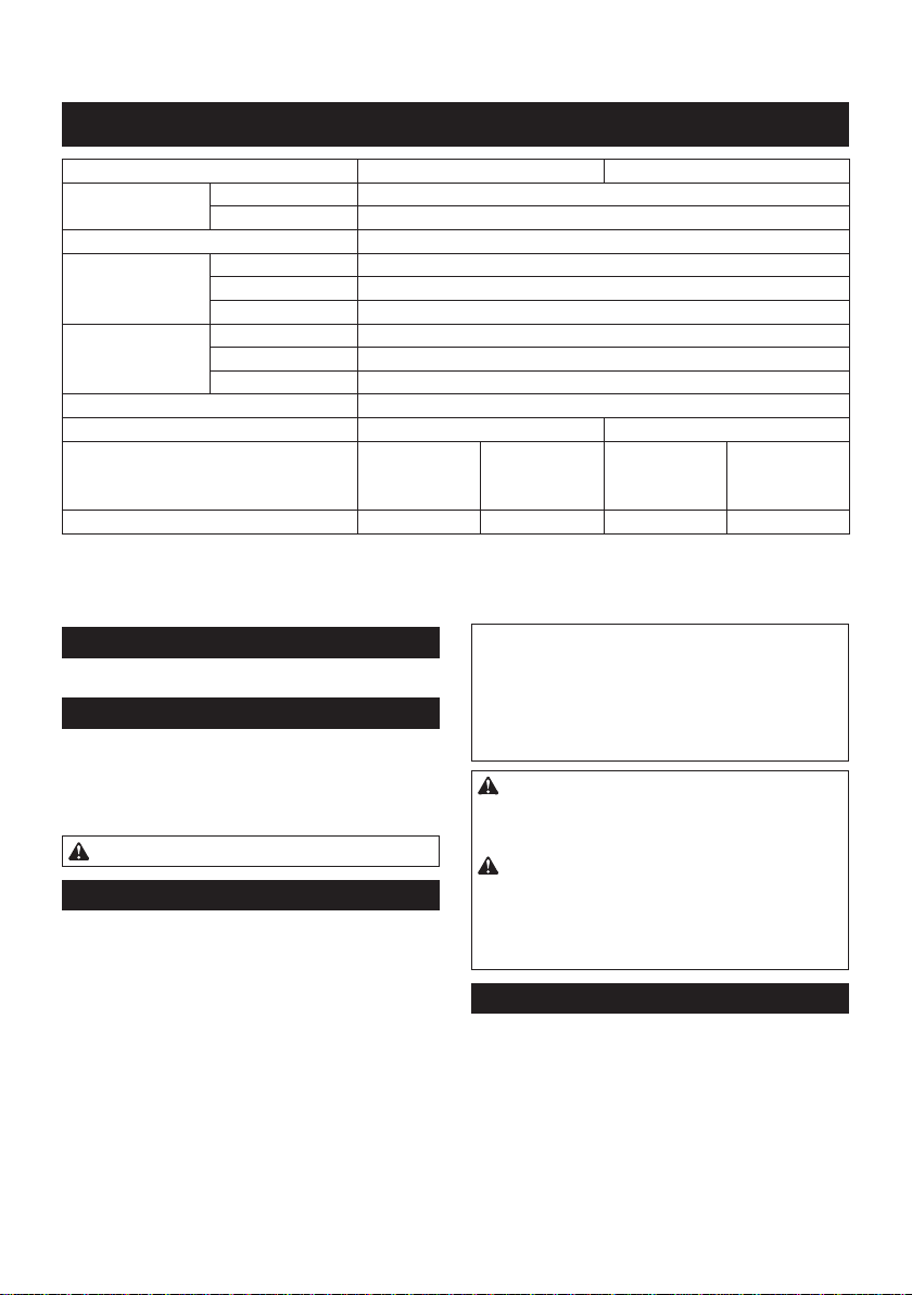
Specications of each impact force grade
Impact force grade displayed
on panel Maximum blows Application Work
H ard 3,5 00 min-1 (/min) Tightening when force and
speed are d esired . Assembling the steel frame.
Med ium 2,6 00 min-1 (/min) Tightening when you need
good c ontrolled pow er. Assembling or disassembling
sc af f old s or f ramew ork.