Makita JN1601 User manual

GB
Nibbler Instruction Manual
F
Grignoteuse Manuel d’instructions
D
Knabber Betriebsanleitung
I
Roditrice Istruzioni per l’uso
NL
Knabbelschaar Gebruiksaanwijzing
E
Roedora Manual de instrucciones
P
Nibbler (ferramenta de corte) Manual de instruções
DK
Pladestanse Brugsanvisning
S
Plåtnibblingsmaskin Bruksanvisning
N
Knabber Bruksanvisning
SF
Nakertaja Käyttöohje
GR Μασουλιστής Οδηγίες χρήσεως
JN1601

2
12
34
56
78
13
11
9
10
12
1
2
4
3
5
6
7
8
12 14
18
1
15
16
2
17

3
910
11 12
13
8
19
1
18
19
2
22
24
23
21
19
20
17
16
15

4
ENGLISH
Explanation of general view
1 Die
2 Die holder
3 Lock nut
4 Wrench
5 Switch lever
6 Gauge for cutting stainless:
1.2 mm
7 Gauge for cutting mild steel:
1.6 mm
8Notch
9 From the top view
10 Cutting at an angle to grooves
11 Cutting perpendicular to
grooves
12 From the side view
13 Corrugated or trapezoidal sheet
metal
14 Cutting head should be at a
right angle (90°) to cutting sur-
face
15 Loosen
16 Tighten
17 Hex wrench
18 Bolts
19 Punch
20 Punch holder
21 Screw
22 Limit mark
23 Brush holder cap
24 Screwdriver
SPECIFICATIONS
Model JN1601
Max. cutting capacities
Steel up to 400 N/mm2........................... 1.6 mm/16 ga
Steel up to 600 N/mm2........................... 1.2 mm/18 ga
Steel up to 800 N/mm2........................... 0.8 mm/22 ga
Aluminum up to 200 N/mm2................... 2.5 mm/13 ga
Min. cutting radius
Outside edge ..................................................... 50 mm
Inside edge ........................................................ 45 mm
Strokes per minute ................................................. 2,200
Overall length ..................................................... 261 mm
Net weight ............................................................. 1.6 kg
• Due to our continuing program of research and devel-
opment, the specifications herein are subject to change
without notice.
• Note: Specifications may differ from country to country.
Power supply
The tool should be connected only to a power supply of
the same voltage as indicated on the nameplate, and can
only be operated on single-phase AC supply. They are
double-insulated in accordance with European Standard
and can, therefore, also be used from sockets without
earth wire.
Safety hints
For your own safety, please refer to the enclosed safety
instructions.
ADDITIONAL SAFETY RULES
1. Always lead the power supply cord away from
the tool towards the rear.
2. Do not touch the blade or the workpiece immedi-
ately after operation; they may be extremely hot
and could burn your skin.
SAVE THESE INSTRUCTIONS.
OPERATING INSTRUCTIONS
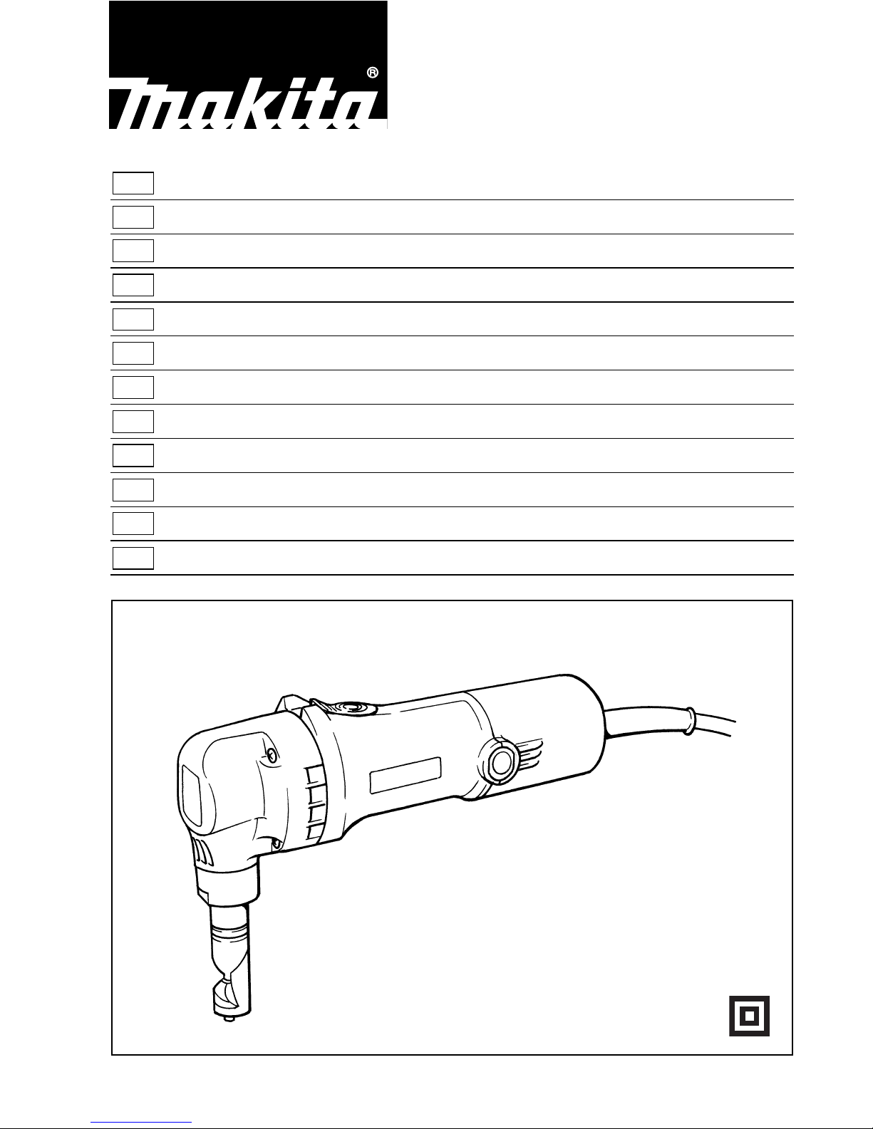
Charging the die position (Fig. 1)
Important:
Always be sure that the tool is switched off and
unplugged before changing the die position.
The die position can be changed 360°. To change it, pro-
ceed as follows.
1. Loosen the lock nut with the wrench provided.
2. Pull the die holder slightly and turn it to the desired
position for operation.
3. Tighten the lock nut to secure the die holder in the
desired position.
There are four positive stops at 90° each: 0°, 90° left and
right and 180°.
To position the die to any of these positive stops:
1. Loosen the lock nut with the wrench provided.
2. Pull the die holder slightly and depress lightly while
turning it to the desired position. The die holder will
lock into one of the positive stop positions as
desired.
3. Turn the die holder slightly to make sure that it is
positively locked into position.
4. Tighten the lock nut to secure the die holder.
Switching ON and OFF (Fig. 2)
Caution:
Before plugging in the tool, always check to see that the
switch actuates properly and returns to the “OFF” posi-
tion when the rear of the switch lever is depressed.
To switch on, depress the rear of the switch lever and
push it forward. Then depress the front of the switch lever
to lock it.
To switch off, depress the rear of the switch lever.
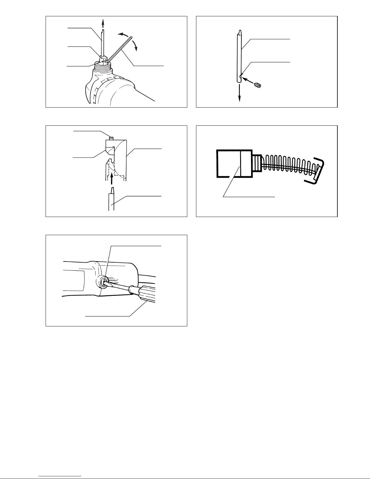
Thickness gauge (Fig. 3)
The groove in the die holder serve as the thickness
gauge for allowable cutting thickness.
Cutting line (Fig. 3)
The notch in the die holder indicates your cutting line. Its
width is equal to the cutting width. Align the notch to the
cutting line on the workpiece when cutting.
Pre-lubrication
Coat the cutting line with tool oil to increase the punch
and die service life. This is particularly important when
cutting aluminum.

5
Cutting method (Fig. 4)
Hold the tool so that the cutting head is at a right angle
(90°) to the workpiece being cut. Move the tool gently in
the cutting direction.
Cutouts (Fig. 5)
Cutouts can be done by first opening a round hole over
21 mm in diameter which the cutting head can be
inserted into.
Cutting the corrugated or trapezoidal sheet
metals (Fig. 6 & 7)
Set the die position so that the die faces the cutting direc-
tion either when cutting at an angle or perpendicular go
grooves in corrugated or trapezoidal sheet metals.
Always hold the tool body parallel to the grooves with the
cutting head at a right angle (90°) to the cutting surface
as shown in Fig. 6 & 7.
Removing or installing the punch and die
(Fig. 1, 8, 9, 10 & 11)
Important:
Always be sure that the tool is switched off and
unplugged before removing or installing the punch and
die.
Always replace the punch and die as a set. To remove
the punch and die, loosen the lock nut with the wrench.
Remove the die holder from the tool. Use the hex wrench
to loosen the bolts which secure the die. Remove the die
from the die holder. Use the hex wrench to loosen the
screw which secures the punch. Pull the punch out of the
punch holder.
To install the punch and die, insert the punch into the
punch holder so that the notch in the punch faces toward
the screw. Tighten the screw to secure the punch. Install
the die on the die holder. Tighten the bolts to secure the
die. Then install the die holder on the tool so that the
punch is inserted through the hole in the die holder.
Tighten the lock nut to secure the die holder. After replac-
ing the punch and die, lubricate them with tool oil and run
the tool for a while.
MAINTENANCE
CAUTION:
Always be sure that the tool is switched off and
unplugged before carrying out any work on the tool.
Replacement of carbon brushes (Fig. 12 & 13)
Replace carbon brushes when they are worn down to the
limit mark. Both identical carbon brushes should be
replaced at the same time.
To maintain product safety and reliability, repairs, mainte-
nance or adjustment should be carried out by a Makita
Authorized Service Center.

12
NEDERLANDS
Verklaring van algemene gegevens
1Mes
2 Meshouder
3 Borgmoer
4Sleutel
5 Hendelschakelaar
6 Diktemaat voor roestvrij staal:
1,2 mm
7 Diktemaat voor zacht staal:
1,6 mm
8 Uitsparing
9 Bovenaanzicht
10 Schuin op de groeven snijden
11 Haaks op de groeven snijden
12 Zijaanzicht
13 Gegolfde of trapezoïdale plaat
14 De snijkop moet haaks (90°) op
het snijvlak staan
15 Losdraaien
16 Vastdraaien
17 Inbussleutel
18 Bouten
19 Drevel
20 Drevelhouder
21 Schroef
22 Limietmarkering
23 Borstelhouderkap
24 Schroevedraaier
TECHNISCHE GEGEVENS
Model JN1601
Max. snijcapaciteit
Staal tot maximaal 400 N/mm2............... 1,6 mm/16 ga
Staal tot maximaal 600 N/mm2............... 1,2 mm/18 ga
Staal tot maximaal 800 N/mm2............... 0,8 mm/22 ga
Aluminium tot maximaal 200 N/mm2...... 2,5 mm/13 ga
Min. snijstraal
Buitenrand ......................................................... 50 mm
Binnenrand ........................................................ 45 mm
Slagen per minuut .................................................. 2.200
Totale lengte ....................................................... 261 mm
Netto gewicht ......................................................... 1,6 kg
• In verband met ononderbroken research en ontwikke-
ling behouden wij ons het recht voor bovenstaande
technische gegevens te wijzigen zonder voorafgaande
kennisgeving.
• Opmerking: De technische gegevens kunnen van land
tot land verschillen.
Stroomvoorziening
De machine mag alleen worden aangesloten op een
stroombron van hetzelfde voltage als aangegeven op de
naamplaat, en kan alleen op enkel-fase wisselstroom
worden gebruikt. De machine is dubbel-geïsoleerd vol-
gens de Europese standaard en kan derhalve ook op
een niet-geaard stopcontact worden aangesloten.
Veiligheidswenken
Voor uw veiligheid dient u de bijgevoegde Veiligheids-
voorschriften nauwkeurig op te volgen.
AANVULLENDE
VEILIGHEIDSVOORSCHRIFTEN
1. Zorg ervoor dat het netsnoer steeds achter en uit
de buurt van de machine blijft.
2. Raak onmiddellijk na de werkzaamheden het
blad noch het werkstuk aan, aangezien het
gloeiend heet kan zijn en brandwonden kan ver-
oorzaken.
BEWAAR DEZE VOORSCHRIFTEN.
BEDIENINGSVOORSCHRIFTEN
De messtand wijzigen (Fig. 1)
Belangrijk:
zorg er altijd voor dat de machine is uitgeschakeld en de
stekker uit het stopkontakt vooraleer de messtand te wij-
zigen.
Het mes kan over 360° worden ingesteld. Om de stand te
wijzigen, gaat u als volgt tewerk:
1. Draai de borgmoer los met behulp van de meegele-
verde sleutel.
2. Trek de houder iets uit en draai hem in de gewenste
werkstand.
3. Draai de borgmoer vast om de meshouder in de
gewenste stand te blokkeren.
Er zijn duidelijk herkenbare standen om de 90°: 0°, 90°
links en rechts en 180°.
Om het mes in één van deze standen te brengen:
1. Draai de borgmoer los met behulp van de meegele-
verde sleutel.
2. Trek de houder iets uit en druk hem weer in terwijl u
hem in de gewenste stand draait. De meshouder
wordt in één van bovenvermelde standen vergren-
deld.
3. Draai lichtjes aan de meshouder om te controleren
dat hij stevig vastzit.
4. Draai de borgmoer vast om de meshouder te blokke-
ren.
AAN en UIT schakelen (Fig. 2)
Opgelet:
alvorens de stekker in het stopcontact te steken, moet u
controleren of de schakelaar correct functioneert en
terugkeert in de “OFF”-stand wanneer de achterkant
wordt ingedrukt.
Om aan te schakelen drukt u de achterkant van de hen-
delschakelaar in en duwt u hem naar voren. Druk dan de
voorkant van de hendelschakelaar in om hem te vergren-
delen.
Om uit te schakelen drukt u op de achterkant van de hen-
delschakelaar.

13
Diktemaat (Fig. 3)
De groeven in de meshouder fungeren als diktemaat
voor het materiaal waarin moet worden gesneden.
Snijlijn (Fig. 3)
De uitsparing in de meshouder geeft de snijlijn aan. De
breedte komt overeen met de snijbreedte. Laat bij het
snijden de uitsparing samenvallen met de snijlijn op het
werkstuk.
Voorsmering
Smeer de snijlijn in met machine-olie om de drevel en het
mes langer mee te laten gaan. Dit is vooral belangrijk bij
het snijden in aluminium.
Snijmethode (Fig. 4)
Hou de machine zo dat de snijkop haaks (90°) op het
werkstuk staat. Beweeg de machine voorzichtig in de
snijrichting.
Uitsnijdingen (Fig. 5)
Om materiaal uit te snijden, maakt u eerst een ronde
opening met een diameter van 21 mm waarin u dan de
snijkop kunt steken.
Gegolfde of trapezoïdale plaat snijden
(Fig. 6 & 7)
Stel het mes zo in dat het mes in de snijrichting wijst
wanneer schuin of haaks op de groeven in gegolfde of
trapezoïdale plaat wordt gesneden. Hou de machine
altijd parallel met de groeven met de snijkop haaks (90°)
op het snijvlak, zoals fig. 6 & 7 laten zien.
De drevel en het mes verwijderen of aanbrengen
(Fig.1,8,9,10&11)
Belangrijk:
zorg er altijd voor dat de machine is uitgeschakeld en de
stekker uit het stopkontakt vooraleer de drevel en het
mes te verwijderen of aan te brengen.
Vervang de drevel en het mes altijd samen. Om de drevel
en het mes te vervangen, draait u de borgmoer los met
de sleutel. Verwijder de meshouder van de machine.
Draai de mesbevestigingsbouten los met behulp van de
inbussleutel. Verwijder het mes uit de houder. Draai de
drevelbevestigingsschroef los met behulp van de inbus-
sleutel. Trek de drevel uit de drevelhouder.
Om de drevel en het mes aan te brengen, steekt u de
drevel in de drevelhouder zodat de uitsparing in de drevel
naar het mes wijst. Draai de schroef vast om de drevel te
blokkeren. Plaats het mes op de meshouder. Draai de
bouten vast om het mes te blokkeren. Plaats vervolgens
de meshouder op de machine zodat de drevel door de
opening in de meshouder steekt. Draai de borgmoer vast
om de meshouder te blokkeren. Na het vervangen van
de drevel en het mes, smeert u ze met machine-olie en
laat u de machine een tijdje draaien.
ONDERHOUD
OPGELET:
Zorg er altijd voor dat de machine is uitgeschakeld en de
stekker uit het stopkontakt vooraleer werken aan de
machine uit te voeren.
Vervangen van koolborstels (Fig. 12 & 13)
Vervang de borstels wanneer ze tot aan de aangegeven
limiet zijn afgesleten. Beide koolborstels dienen tegelij-
kertijd te worden vervangen.
Opdat het gereedschap veilig en betrouwbaar blijft, die-
nen alle reparaties, onderhoud of afstellingen te worden
uitgevoerd in een erkend Makita service centrum.

28
ENH101-5
EC-DECLARATION OF CONFORMITY
We declare under our sole responsibility that this product
is in compliance with the following standards of standard-
ized documents,
EN60745, EN55014, EN61000
in accordance with Council Directives, 89/336/EEC and
98/37/EC.
DÉCLARATION DE CONFORMITÉ CE
Nous déclarons sous notre entière responsabilité que ce
produit est conforme aux normes des documents stan-
dardisés suivants,
EN60745, EN55014, EN61000
conformément aux Directives du Conseil, 89/336/CEE et
98/37/EG.
CE-KONFORMITÄTSERKLÄRUNG
Hiermit erklärt wir unter unserer alleinigen Verantwor-
tung, daß dieses Produkt gemäß den Ratsdirektiven
89/336/EWG und 98/37/EG mit den folgenden Normen
von Normendokumenten übereinstimmen:
EN60745, EN55014, EN61000.
DICHIARAZIONE DI CONFORMITÀ
CON LE NORME DELLA COMUNITÀ EUROPEA
Dichiariamo sotto la nostra sola responsabilità che
questo prodotto è conforme agli standard di documenti
standardizzati seguenti:
EN60745, EN55014, EN61000
secondo le direttive del Consiglio 89/336/CEE e 98/37/CE.
EG-VERKLARING VAN CONFORMITEIT
Wij verklaren hierbij uitsluitend op eigen verant-
woordelijkheid dat dit produkt voldoet aan de volgende
normen van genormaliseerde documenten,
EN60745, EN55014, EN61000
in overeenstemming met de richtlijnen van de Raad
89/336/EEC en 98/37/EC.
DECLARACIÓN DE CONFORMIDAD DE LA CE
Declaramos bajo nuestra sola responsabilidad que este
producto cumple con las siguientes normas de docu-
mentos normalizados,
EN60745, EN55014, EN61000
de acuerdo con las directivas comunitarias,
89/336/EEC y 98/37/CE.
Yasuhiko Kanzaki
CE 2005
Director Amministratore
Directeur Directeur
Direktor Director
MAKITA INTERNATIONAL EUROPE LTD.
Michigan Drive, Tongwell, Milton Keynes,
Bucks MK15 8JD, ENGLAND
Responsible manufacturer: Produttore responsabile:
Fabricant responsable :Verantwoordelijke fabrikant:
Verantwortlicher Hersteller: Fabricante responsable:
Makita Corporation Anjo Aichi Japan
ENGLISH
FRANÇAISE
DEUTSCH
ITALIANO
NEDERLANDS
ESPAÑOL

29
ENH101-5
DECLARAÇÃO DE CONFORMIDADE DA CE
Declaramos sob inteira responsabilidade que este
produto obedece às seguintes normas de documentos
normalizados,
EN60745, EN55014, EN61000
de acordo com as directivas 89/336/CEE e 98/37/CE do
Conselho.
EU-DEKLARATION OM KONFORMITET
Vi erklærer hermed påeget ansvar, at dette produkt er i
overensstemmelse med de følgende standarder i de norm-
sættende dokumenter,
EN60745, EN55014, EN61000
i overensstemmelse med Rådets Direktiver 89/336/EEC
og 98/37/EC.
EG-DEKLARATION OM ÖVERENSSTÄMMELSE
Under eget ansvar deklarerar vi härmed att denna
produkt överensstämmer med följande standardiseringar
för standardiserade dokument,
EN60745, EN55014, EN61000
i enlighet med EG-direktiven 89/336/EEC och 98/37/EC.
EUs SAMSVARS-ERKLÆRING
Vi erklærer påeget ansvar at dette produktet er i over-
ensstemmelse med følgende standard i de standardis-
erte dokumenter:
EN60745, EN55014, EN61000,
i samsvar med Råds-direktivene, 89/336/EEC og 98/37/
EC.
VAKUUTUS EC-VASTAAVUUDESTA
Yksinomaisesti vastuullisina ilmoitamme, ettätämätuote
on seuraavien standardoitujen dokumenttien standar-
dien mukainen,
EN60745, EN55014, EN61000
neuvoston direktiivien 89/336/EEC ja 98/37/EC mukai-
sesti.
∆ΗΛΩΣΗ ΣΥΜΜΟΡΦΩΣΗΣ ΕΚ
∆ λώνουµε υπ τ ν µοναδική µας ευθύν τι αυτ
το προιν βρίσκεται σε Συµφωνία µε τα ακλουθα
πρτυπα τυποποι µένων εγγράφων,
EN60745, EN55014, EN61000
σύµφωνα µε τις Οδ γίες του Συµβουλίου,
89/336/EEC και 98/37/ΚE.
Yasuhiko Kanzaki
CE 2005
Director Direktor
DirektørJohtaja
Direktör∆ιευθυντής
MAKITA INTERNATIONAL EUROPE LTD.
Michigan Drive, Tongwell, Milton Keynes,
Bucks MK15 8JD, ENGLAND
Fabricante responsável: Ansvarlig produsent:
Ansvarlig fabrikant: Vastaava valmistaja:
Ansvarig tillverkare: Υπεύθυνος κατασκευαστής:
Makita Corporation Anjo Aichi Japan
PORTUGUÊS
DANSK
SVENSKA
NORSK
SUOMI
ΕΛΛΗΝΙΚΑ

30
ENG003-2-V2
For European countries only
Noise and Vibration
The typical A-weighted sound pressure level is 83 dB (A).
Uncertainty is 3 dB (A).
The noise level under working may exceed 85 dB (A).
–Wear ear protection. –
The typical weighted root mean square acceleration
value is not more than 2.5 m/s2.
These values have been obtained according to
EN60745.
Pour les pays d’Europe uniquement
Bruit et vibrations
Le niveau de pression sonore pondere type A est de
83 dB (A).
L’incertitude de mesure est de 3 dB (A).
Le niveau de bruit en fonctionnement peut dépasser
85 dB (A).
–Porter des protecteurs anti-bruit. –
L’accélération pondérée ne dépasse pas 2,5 m/s2.
Ces valeurs ont étéobtenues selon EN60745.
Nur für europäische Länder
Geräusch- und Vibrationsentwicklung
Der typische A-bewertete Schalldruckpegel beträgt
83 dB (A).
Die Abweichung beträgt 3 dB (A).
Der Lärmpegel kann während des Betriebs 85 dB (A)
überschreiten. –Gehörschutz tragen. –
Der gewichtete Effektivwert der Beschleunigung beträgt
nicht mehr als 2,5 m/s2.
Diese Werte wurden gemäß EN60745 erhalten.
Modello per l’Europa soltanto
Rumore e vibrazione
Il livello di pressione sonora pesata secondo la curva A è
di 83 dB (A).
L’incertezza èdi 3 dB (A).
Il livello di rumore durante il lavoro potrebbe superare gli
85 dB (A).
–Indossare i paraorecchi. –
Il valore quadratico medio di accellerazione non supera i
2,5 m/s2.
Questi valori sono stati ottenuti in conformitàEN60745.
Alleen voor Europese landen
Geluidsniveau en trilling
Het typische A-gewogen geluidsdrukniveau is 83 dB (A).
Onzekerheid is 3 dB (A).
Tijdens het werken kan het geluidsniveau 85 dB (A) over-
schrijden. –Draag oorbeschermers. –
De typische gewogen effectieve versnellingswaarde is
niet meer dan 2,5 m/s2.
Deze waarden werden verkregen in overeenstemming
met EN60745.
Para países europeos solamente
Ruido y vibración
El nivel de presión sonora ponderada A es de 83 dB (A).
Incerteza 3 dB (A).
El nivel de ruido en condiciones de trabajo puede que
sobrepase los 85 dB (A).
–Póngase protectores en los oídos. –
El valor ponderado de la aceleración no sobrepasa los
2,5 m/s2.
Estos valores han sido obtenidos de acuerdo con
EN60745.
ENGLISH
FRANÇAISE
DEUTSCH
ITALIANO
NEDERLANDS
ESPAÑOL

31
ENG003-2-V2
Só para países Europeus
Ruído e vibração
O nível normal de pressão sonora A é83 dB (A).
A incerteza éde 3 dB (A).
O nível de ruído durante o trabalho pode exceder
85 dB (A).
–Utilize protectores para os ouvidos –
O valor médio da aceleração éinferior a 2,5 m/s2.
Estes valores foram obtidos de acordo com EN60745.
Kun for lande i Europa
Lyd og vibration
Det typiske A-vægtede lydtryksniveau er 83 dB (A).
Der er en usikkerhed på3dB(A).
Støjniveauet under arbejde kan overstige 85 dB (A).
–Bær høreværn. –
Den vægtede effektive accelerationsværdi overstiger ikke
2,5 m/s2.
Disse værdier er beregnet i overensstemmelse med
EN60745.
Endast för Europa
Buller och vibration
Den typiska-A-vägda ljudtrycksnivån är 83 dB (A).
Osäkerheten är 3 dB (A).
Bullernivån under pågående arbete kan överstiga
85 dB (A).
–Använd hörselskydd –
Det typiskt vägda effektivvärdet för acceleration översti-
ger inte 2,5 m/s2.
Dessa värden har erhållits i enlighet med EN60745.
Gjelder bare land i Europa
Støy og vibrasjon
Det vanlige A-verktet lydtrykksnivåer 83 dB (A).
Usikkerheten er på3 dB (A).
Under bruk kan støynivået overskride 85 dB (A).
–Benytt hørselvern. –
Den typiske vektede effektive akselerasjonsverdi over-
skrider ikke 2,5 m/s2.
Disse verdiene er beregnet eller målt i samsvar med
EN60745.
Vain Euroopan maat
Melutaso ja tärinä
Tyypillinen A-painotettu äänenpainetaso on 83 dB (A).
Epävarmuus on 3 dB (A).
Melutaso työpaikalla saattaa ylittää 85 dB (A).
–Käytäkuulosuojaimia. –
Tyypillinen kiihtyvyyden painotettu tehollisarvo ei ylitä
2,5 m/s2.
Nämäarvot on mitattu normin EN60745 mukaisesti.
Μ.νο για χώρες της Ευρώπης
Θ.ρυβος και κραδασµ.ς
Η τυπική Α-µετρούµεν χ τική πίεσ είναι
83 dB (A).
Η Αβεβαιτ τα είναι 3 dB (A).
Η έντασ ήχου υπο συνθήκες εργασίας µπορεί να
µπερβεί τα 85 dB (A).
– Φοράτε ωτοασπίδες. –
Η τυπική αξία τ ς µετρούµεν ς ρίζας του µέσου
τετραγώνου τ ς επιτάχυνσ ς δεν ξεπερνά τα
2,5 m/s2.
Αυτές οι τιµές έχουν σ µειωθεί σύµφωνα µε το
ΕΝ60745.
PORTUGUÊS
DANSK
SVENSKA
NORSK
SUOMI
ΕΛΛΗΝΙΚΑ

Makita Corporation
Anjo, Aichi, Japan
883894D993
Other manuals for JN1601
17
Table of contents
Languages:
Other Makita Power Tools manuals

Makita
Makita WT001G User manual

Makita
Makita HM1800 User manual

Makita
Makita MT01 User manual

Makita
Makita HR008G User manual

Makita
Makita UP100D User manual

Makita
Makita DHK180 User manual

Makita
Makita HR004G User manual

Makita
Makita DTW1001 User manual

Makita
Makita XPK01 User manual

Makita
Makita MJV430 User manual

Makita
Makita HM0810T User manual

Makita
Makita JS1601 Manual

Makita
Makita HM0870C User manual

Makita
Makita BSS500 User manual

Makita
Makita HK0500 User manual

Makita
Makita VR001G User manual

Makita
Makita HM1304 User manual

Makita
Makita TW100D Series User manual

Makita
Makita 5093DWA User manual

Makita
Makita HM1317C User manual