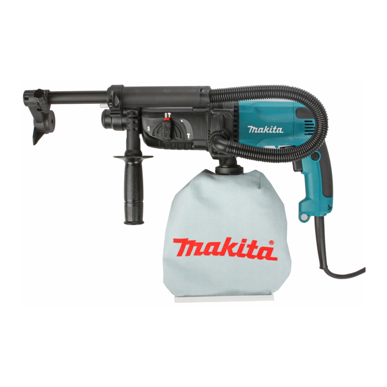
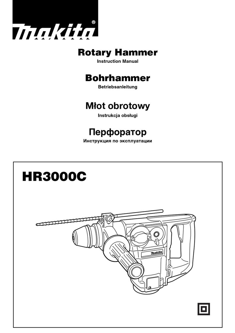
Makita HR4500C User manual

Specifications
CONCEPTION AND MAIN APPLICATIONS
Models No.
Description
PRODUCT
P 1 / 16
Dimensions : mm ( " )
Width (W)
Height (H)
Length (L)
118mm (4-5/8")
488mm (19-1/4")
For matured line-up of SDS-Max Rotary Hammers, Model HR4500C
has been developed as a sister model to HR4000C(40mm;1-3/4") and
HR5001C(50mm;2") which are already popular to users around the
world.
HR4500C
Rotary Hammer 45mm (1-3/4")
278mm (11")
Continuous Rating (W)
Voltage (V) Current (A) Cycle (Hz) Input Output Max. Output(W)
120
110 13 50/60 1,300 600 1,500
100 15 50/60 1,300 600 1,500
13 50/60 1,250 600 1,500
1,500
1,500
1,500
220 6.6 50/60 1,300 600
230 6.6 50/60 1,300 600
240 6.8 50/60 1,300 600
TECHINICAL INFORMATION
Performing excellent drilling in concrete within the diameter range
from 25mm(1") to 45mm(1-3/4"), it also has the same features and
benefits as HR4000C and HR5001C.
Hammer Grease (30cc), Blow-out Bulb, Dust Cup 5, Dust Cup 9, Bull Point, Cold Chisel, Scaling Chisel,
Clay Spade, Bushing Tool, Rammer, Safety Goggles, Core Bit Adapter,
Core Bits; Hole diameter : 20mm(13/16"), 30mm(1-3/16"), 35mm(1-3/8"), 40mm(1-9/16"), 45mm(1-3/4"),
54mm(2-1/8"), 65mm(2-9/16"), 79mm(3-1/8"), 105mm(4-1/8"), 118mm(4-5/8")
Tungusten-carbide Tipped Bits; Bit diameter : 10mm(3/8"), 10.5mm(7/16"), 11mm(7/16"), 12mm(15/32"),
12.5mm(1/2"), 12.7mm(1/2"), 13.5mm(1/2"), 14.3mm(9/16"),
14.5mm(9/16"), 16mm(5/8"), 17mm(11/16"), 17.5mm(11/16"),
18mm(11/16"), 19mm(3/4"), 20mm(13/16"), 21.5mm(7/8"),
22mm(7/8"). 24mm(15/16"), 25mm(1"), 25.4mm(1"), 26mm(1"),
28mm(1-1/8"), 30mm(1-3/16"), 32mm(1-1/4"), 35mm(1-3/8"),
38mm(1-1/2")
120 - 240
1,250 - 2,550
SDS-Max shank bit
18 (11/16")
No load speed Rotations per minute : rpm=min-1
Blows per minute : bpm=min-1
Bit type
Diameter of shank : mm (")
Drilling capacities
: mm (")
Net weight : Kg (lbs)
Cord length : m (ft)
7.8 (17.2)
Standard spec. : 5 (16.4)
European spec. : 4 (13.1)
STANDARD EQUIPMENT
45 (1-3/4")
Tungusten-carbide
tipped bit
Core bit 125 (4-7/8")
Grip 36 Assembly
(Bar style side handle) ------------ 1pc.
Depth Gauge ----------------------- 1pc.
Grease Vessel (Bit Grease) ------- 1pc.
Plastic Carrying Case ------------- 1pc.
Side Handle Assembly
(D-shaped side handle) ----------- 1pc.
OPTIONAL ACCESSORIES
The standard equipment for the machine may differ from country to country.
See next page for detailed information.
L
W
H
P 2 / 16
Features and benefits
No electric shock to operator, even if bit accidentally hits against laid electric cables.
Barrel is also covered with resin, and so, it is possible to do chipping operations while
holding barrel with your hand.
Body Wholly Covered
with Resin
The Outstanding Chipping Power in This Class
See next page for the excellent results of various chipping/drilling tests.
Zig-Zag Varnish on Armature Coil Protects Armature against dust, and disperses heat effectively.
Accepts SDS-Max Shank Bits
Bit can be Installed or Removed by Simply Sliding Chuck Cover.
No Hammering While Idling
Air in the cylinder is not compressed unless tool is pressed against ground.
This function ensures machine's long life.
Bar Handle Plus D-Shape Handle As Standard Accessories
Large Change Lever
Easy to change action mode to "hammering only" or "Rotation with hammering".
Fingers are free from fatigue even in along continuous operation.
Easy-to-Operate Large Trigger
Can be gripped with both hands. - convenient for downward chipping operations.
Large Rear Handle
Optimum hammering speed can be selected for a wide range of applications. Setting to low speed, ideal for such
a light chipping works as scraping tiles, removing bricks joint.
Electronic Speed Control Dial
Torque Limiter Actuated by Ball-Clutch
Assures steady torque control even after a long time operation.
Chisel can be Locked at 12 Positions Through 360 .
By turning change ring while pushing it forward, the chisel angle can be adjusted without taking out the inserted chisel.
Further Improvement in Dust Proof Structure
2
1
3
4
6
7
Accessible to Switch or Power Supply Cord Just by Removing Two Screws of Handle Cover
8
Service Reminder Lamps
Light up in green when the machine is switched on, and if any trouble, tell you its cause;
Light up, but the machine does not start.
Cause : wear of carbon brushes or trouble(s) in electric circuit or motor
Does not light up, and the machine does not start.
Cause : disconnection in mains switch or power supply cord
Light up in red nearly 8 hours before carbon brushes need servicing.
9
Large and Tough Cord Guard
Also excellent in flexibility to protect cable from disconnection
10
11
Protect commutator and tell the time for replacement.
Auto Shut-off Carbon Brushes
12
13
14
15
5
1
24
3567
8
9
10
11
12
14
15
13

P 3 / 16
Comparison chart
The four graphs drawn below show the results of our chipping or drilling tests under the following conditions;
HR4500C
A-1
A-a
B
Little Much
100
115
105
95
120
85
90
HR5001C
HR3850
HR4000C
50 100 150 200
1. ø25mm hole
HR4500C
100
120
130
95
155
110
105
HR5001C
HR3850
HR4000C
50 100 150 200
2. ø28mm hole
HR4500C
100
100
100
125
135
110
185
HR5001C
HR3850
HR4000C
50 100 150 200
3. ø35mm hole
HR4500C
100
120
115
100
145
HR5001C
HR3850
HR4000C
50 100 150 200
Slow Fast
Slow Fast
Slow Fast
Chipping amount
material : concrete whose compressive strength is 350 kgf/cm
in horizontal application
The results are shown in relative values when setting Model A-a of competitor A's data as 100.
Drilling speed
90
75
2
A-1
A-a
B
A-1
A-a
B
A-1
A-a
B

P 4 /16
Comparison of products
Standard
equipment
Net weight : Kg(lbs)
(Not includes side handle
and power supply cord)
Double insulation
Cord length : mm (ft)
Noise level (dB[A]) 92 91 95 90 93 98
Yes
7.8 (17.2) 7.9 (17.4) 7.5 (16.5) 6.2 (13.7)
Yes Yes Yes Yes Yes
7.0 (15.4)
7.9 (17.4)
Yes Yes Yes Yes Yes
Yes
Yes No No
YesNo No No
Yes Yes
Yes Yes Yes Yes Yes Yes
Yes Yes
Yes
Yes Yes Yes Yes
Plastic
carrying
case
Bit grease
Depth
gauge
Bar style
side handle
D-shaped
side handle
*Rotation with Hammering mode / Hammering mode
**European spec.
Yes
Makita
Model No.
Competitor A Makita
Competitor B
HR4500C A-1 BA-a HR4000C HR5001C
45 (1-3/4) 45 (1-3/4)
282
37 (1-7/16) 45 (1-3/4) 40 (1-9/16) 50 (2)
125 (4-7/8)
1,300
13
120-240
11.7 9.6 15
120 - 240100 - 240 230 - 450185 - 255
1,300
0 - 200
1,050 1,150 1,050 1,500
150 (5-7/8) 160 (6-5/16) 125 (4-7/8)
T.C.T
bit
Continuous rating
Input (W)
Blows per minute
Continuous rating
current (A) on 120V
Yes No YesYes YesNo
Max. drilling
capacity
: mm (")
No load speed
: min-1=rpm
Single-blow energy
(Joule)
2 action mode* settings Yes
Yes Yes No
Yes Yes Yes Yes
8.3 8.3 9.0 :rotary hammer
11.0 :hammer 6.78.0 17.5
Slide lock by one action
No Yes Yes No No No
Core
bit 105 (4-1/8) 160 (6-5/16)
1,250 - 2,550 1,200 - 2,800 1,250 - 2,500 1,100 - 2,1500 - 2,750 0 - 2,700
YesYes
Yes No No No Yes Yes
Yes Yes Yes Yes
Service reminder lamp
for carbon brushes
Electronic speed
control dial
Trigger switch with
variable speed control
Service reminder lamp
to notify troubles in
switch and cord
Yes
A-1C
10.0 (22.1)
Bit shank type SDS-Max SDS-Max SDS-Max SDS-Max SDS-Max SDS-Max
Yes
Yes Yes Yes
Vibration (m/s ) 11 11 11.5 10 13
8
2
5 (16.4)
**4 (13.1) 4 (13.1) 4 (13.1) 4 (13.1) 5 (16.4)
**4 (13.1) 5 (16.4)
**4 (13.1)
7
Dimensions
: mm (")
Length
Height
Width
(1)
(2)
488 (19-1/4) 497 (19-1/2)
278 (11)
118 (4-5/8)
495 (19-1/4)
259 (11)
114 (4-5/8)
455 (17-7/8)
253 (10)
100 (3-15/16)
610 (24)
280 (11)
118 (4-5/8)
540 (21-1/4)
265 (10-3/8)
98 (3-7/8)
261 (10-1/4)
115 (4-1/2)
510 (20)
288 (11-3/8)
115 (4-1/2)

Repair P 5 / 16
< 1 > Lubrication
Apply MAKITA grease No.00 to the following parts in order to prevent unusual abrasion and overheating.
Apply to O ring 27.
Striker
Ring 38
Apply to the inside.
Spiral bevel gear 36
Apply to the outside and teeth portion.
Rod
Apply to hole for
crank shaft accepting.
Piston
Apply to the whole part of Impact bolt.
Oil seal 15 to be
assembled to gear side shaft
of armature
Oil seal 35
Apply to the lip portion.
Gear housing
Slide sleeve
Apply to the lip portion.
Torque limiter
Spur gear 10 Apply to this portion where
spur gear 10 does not engage
torque limiter.
<2> Disassembling Change Lever Complete
Set Change Lever Complete at neutral position,
and slightly hit the back side of lock button with a plastic hammer to remove it.
(See Fig.1.)
Fig. 1
plastic hammer
Lock button
Change lever
at neutral position.
Apply to O ring 27.
Apply to needle bearing.
Apply to this portion where
spur gear 10 does not engage
torque limiter.

Repair P 6 / 16
<3> Assembling Change Lever
2) Assemble change lever on crank housing
with setting crank pin 4 into the upper hole (elliptic hole)
of change link. See Fig. 3.
( The change lever has to be set at hammering position.)
1) Change link is constructed to be slid up and down.
Slide the change link upward with your finger.
(See Fig.2)
Figure 2
(See Fig 3A)
Remark Do not operate the machine without change lever.
Otherwise it causes damage of the inner mechanism.
Change link
slid upward
with finger
Upper hole of change link
Crank pin 4 has to be
set into the upper hole
(elliptic hole) of change link
Change lever
Fig. 3
Fig. 4
Position of
Crank pin 4
( The change lever has to be set at hammering position.)
Fig. 3A
<3> Disassembling armature
1) Remove tool holder cap while pulling chuck cover down. See Fig. 4.
Then chuck cover can be removed from the machine.
2) Take off pan head screw M4x16 which is fixing crank housing cover
on crank housing. See Fig. 4.
Pan head screw M4x16
Chuck cover
Tool holder cap
Crank housing cover

Repair P 7 / 16
3) Insert a stainless scale into the change lever assembling hole of crank housing, and put the another end
of the same scale on side handle base as illustrated in Fig. 5.
4) Strike side grip with plastic hammer. So crank housing cover can be separated together with side grip
from crank housing as illustrated in Fig. 5A.
Stainless scale
Insert into the
change lever
installing hole
of crank housing.
Side handle base
Fig. 5A
Fig. 5
Fig. 6
Crank housing cover
5) Disassemble handle by unscrewing pan head screws and tapping screws as illustrated in Fig. 6.
6) Disassemble connector and fix rod as illustrated in Fig. 6.
7) And then, remove pick-up coil as illustrated in Fig. 6.
Tapping screws M5x20
Pan head screws M5x20
Handle
Connector
Fix rod
Pick-up coil
Controller
Control dial
< Note > Keep the following matters in order to avoid the disconnection, when removing pick-up coil and connector.
1. After disassembling fix rod, remove pick-up coil.
2. When separating connector from controller, hold controller with a hand,
and pull connector itself, holding it with another hand. Do not remove pulling connector's lead wires.
8) Pull off 3 terminals (white, red and black) from controller as illustrated in Fig. 7.
Then, controller can be removed from motor housing.
3 terminals pulled off
from controller
White
Red
Black
Controller
Fig. 7

Repair P 8 / 16
9) Disassemble rear cover, brush holder cover, brush holder cap and carbon brush from motor housing
as illustrated in Fig. 8.
10) Hold fan with your gloved hand. And disassemble fan by unscrewing hex nut M8 with impact driver
as illustrated in Fig. 9. And then, separate crank housing from motor housing by unscrewing tapping
screw M5x20. as illustrated in Fig. 9A.
Fig. 8
Carbon brush
Motor housing
Rear cover
Brush holder cover
Tapping screw M4x18
Brush holder cap
Tapping screws M5x20
Bottom view of motor housing
and fan
Hex nut M8
Flat washer 8
Fan
Tapping screws M5x20
Fig. 9
Fig. 9A.
Impact driver
11) Separate armature section from motor housing by striking the rear side of armature shaft as illustrated in Fig. 10.
And then, disassemble armature with the repairing tool No.1R045 from gear housing as illustrated in Fig. 10A.
Strike the rear side of
armature shaft.
Fig. 10
No.1R045 Large gear extractor
Fig. 10A.
Gear housing
Armature
Gear housing

Repair P 9 / 16
1) Assemble oil seal 15 and ball bearing 6202LLU to gear housing as illustrated in Fig. 12.
<4> Assembling armature
Oil seal 15
Ball bearing 6202LLU
Gear housing
Fig. 12 Fig. 12A
Press
Press
2) Assemble baffle plate and flat washer 15 to armature as illustrated in Fig. 13. And then, assemble the armature
to gear housing by pressing.
Flat washer 15
Baffle plate
Armature
<5> Disassembling chuck section
1) Disassemble tool holder cap, chuck cover and crank housing cover as illustrated in Fig.4, Fig. 5 and Fig. 5A at
page 6 and 7.
3) Disassemble shoulder pin 8 after removing leaf spring 37 from chuck ring as illustrated in Fig. 14A.
2) Disassemble ring spring 25 and retaining ring WR-40 with No.1R003 "retaining ring S plier"
equipped with No.1R212 "nail for ring spring" as illustrated in Fig. 14.
Then, washer 40 and compression spring 50 can be removed from tool holder.
Fig. 13
Ring spring 25
Retaining ring WR-40
Washer 40
Compression spring 50
Fig. 14
Tool holder
Chuck ring
Leaf spring 37
Shoulder pin 8
Fig. 14A
No.1R003
Retaining ring S plier
No.1R212
Nail for ring spring
Ring spring

Repair P 10 / 16
<6> Assembling chuck section
1) Assemble shoulder pin 8 to chuck ring. And then assemble leaf spring 37 to the chuck ring as illustrated in Fig. 15.
<Note> The bulge of shoulder pin 8 has to meet the hole of leaf spring 37, when assembling leaf spring
to chuck ring. See Fig. 15A.
Leaf spring 37
Shoulder pin 8
Chuck ring
Fig. 15
Fig. 15A
2) Assemble compression spring 50 and washer 40. And then, fix them on tool holder with retaining ring WR-40
and ring spring 25. See Fig. 15B.
Ring spring 25
Retaining ring WR-40
Washer 40
Compression spring 50
Tool holder
Chuck ring
Leaf spring 37
The bulge has to
meet the hole of leaf
spring 37.
Fig. 15B
<7> Disassembling tool holder from crank housing
1) Put a driver with slotted bit into the concave portion of seal case and slightly strike the driver as illustrated in Fig. 16.
Then, seal case can be removed from crank housing.
2) Remove retaining ring R-62 with No.1R005 "retaining ring plier for hole". And pull off tool holder
as illustrated in Fig. 16A. If it is hard to remove by pulling off with your hand, you can remove tool holder
as illustrated in Fig. 16B.
Concave portion
of seal case
Seal case
Fig. 16
Slightly strike the
driver.
Retaining ring R-62 Tool holder
Fig. 16B
Fig. 16A
Slightly strike the edge of crank housing,
with holding the screwdriver with your hand.

Repair P 11 / 16
<8> Disassembling lock sleeve A and B from tool holder
1) Hold tool holder on which lock sleeve A and B are installed, by pressing with arbor press as illustrated in Fig. 17.
2) Disassemble retaining ring S-35 with No.1R003 "retaining ring S plier as illustrated in Fig. 17A.
Fig. 17
Hold by pressing with arbor press.
1R032 Bearing
setting plate
Tool holder
60mm
No.1R003
Retaining ring S plier
Fig. 17A
Lock sleeve A
Lock sleeve B
Ball bearing
6007LLU
Retaining ring S
3) Disassemble ball bearing 6007LLU with No. 1R045 "large gear extractor" as illustrated in Fig. 17B.
After removing the ball bearing, lock sleeve A and B can be disassembled from tool holder.
No. 1R045 Large gear extractor
Set flat metal plate (like as lock nut
wrench for angle grinder) as a support.
Pull lock sleeve B downward so
that you can hitch ball bearing 6007LLU
with "large gear extractor".
Lock sleeve B
Ball bearing 6007LLU
<9> Disassembling torque limiter section
1) Remove retaining ring S-16 from crank shaft as illustrated in Fig. 18.
2) Remove helical gear 37 from crank shaft. Then, torque limiter section can be disassembled from crank housing.
See Fig. 18 A and Fig. 18B.
Crank shaft
Retaining ring S-16
Torque limiter section
Crank shaft
Torque limiter section
Helical gear 37
Crank shaft
Torque limiter section
Fig. 17B
Fig. 18 Fig. 18 A
Fig. 18B

Repair P 12 / 16
<10> Disassembling crank shaft
1) Remove retaining ring R-55 which is fixing crank shaft, from crank housing as illustrated in Fig. 19.
3) Separate crank shaft from crank housing by slightly striking the edge of crank housing as illustrated in Fig. 19B.
Retaining ring R-55
2) Face the key installing groove of crank shaft to the side of crank housing by turning crank shaft
as illustrated in Fig. 19A.
Fig. 19 Fig. 19A
Key installing groove
Crank shaft
Fig. 19B
<11> Disassembling cylinder 34
Tension Spring,
Item No.231791-4
Push and open it
Turn to right, and
pull out Cylinder.
Left screw
Crank Case
Cylinder
Adjust Extractor so that
Pin may enter Cylinder
hole properly.
1R213
No.1R213 : Cylinder Extractor
Pull out Cylinder of Rotary Hammer.
Pull out by hanging the Pin at
the tip of Cylinder Puller on the
side hole of Cylinder.
Pull out cylinder 34 with 1R213 "cylinder extractor:" as illustrated in Fig. 20.
Fig. 20

Repair P 13 / 16
1) Assemble 2 pcs of O rings 35 to cylinder 34, and insert piston to which 2 pcs. of O rings 27 and rod have to be
assembled in advance, into the cylinder 34 as illustrated in Fig. 21. And then, assemble flat washer 45
to crank housing.
<12> Assembling reciprocating section
2) Further push the piston, until the hole of rod can be seen through the crank cap installing hole of crank housing.
See Fig. 21A.
3) Press the crank shaft into crank housing with fitting the pin of crank shaft in the hole of rod. as illustrated in Fig. 21B.
O rings 35
Rod
O ring 27
Piston Crank cap installing hole
of crank housing
Cylinder 34
Cylinder 34
Crank cap installing hole
of crank housing
Pin of crank shaft
Hole of rod
Piston
Fig. 21A
Flat washer 45
Fig. 21B
The key installing groove of crank shaft
has to be faced to the side of crank housing,
when assembling.
Fig. 21
<13> Assembling fluoride ring 25 to impact bolt
1. After installing fluoride ring 20 on impact bolt,
the ring comes stretched and its edge come protruding
from the groove. (see Fig. 22)
2. In order to correct the deformation, insert impact bolt
with the fluoride ring 20 into the repairing tool, Taper
sleeve (No.1R259) and leave it in the repairing
tool about 10 seconds. (see Fig. 22A)
3. When inserting impact bolt into tool holder, be careful
not to put the ring out of the groove of impact bolt.
grooves on
Impact Bolt
Fluoride Ring 25
O ring 20
Before Correction :
Rings' edges are protruding from grooves
of Impact Bolt.
1R259 Taper Sleeve
Correction
After Correction :
Rings' edges are placed under grooves
of Impact Bolt.
Impact Bolt
corrected
Hole of rod
Ball bearing 6006LLU
Fig. 22 Fig. 22A Fig. 22B

Repair P 14 / 16
<13> Assembling crank housing section
<14> Assembling tool holder section
1. Assemble the following parts to tool holder. (see Fig. 24)
Urethane ring 35
Flat washer 35
Lock sleeve A
Compression spring 55
Lock sleeve B
Flat washer 49
Ball bearing 6007LLU
Retaining ring R-35
Tool holder
1. Assemble the the spare parts of Fig.23 into
the crank housing.
Washer 19
Rubber ring 22
Sleeve 19
Slide sleeve
Ring 38
Compression spring 39
Striker with
O ring 27
Spiral
bevel gear 36 Crank housing
Tool holder
< Note >
Spiral bevel gear 36 can be smoothly installed
into the crank housing by pushing it with tool
holder. (see Fig.23A)
Fig.23A
Fig.23
2. When pressing tool holder into spiral bevel gear 36,
the cams on tool holder and the same
of spiral bevel gear 36 have to engage each other.
(see Fig. 25A)
* Adjust 16 concaves of spiral bevel gear 36
to 6 concaves of crank housing by turning
spiral bevel gear 36. (see Fig.25)
* Adjust the cams of lock sleeve A to the
same of tool holder. (see Fig.25A)
* Press tool holder into crank housing with
adjusting as follow.
- Face the flat section of lock sleeve A to the
hole for change lever installing.
- Engage 6 convexes of lock sleeve B with
6 concaves of crank housing.
(see Fig.25 and 25A)
Fig.25
6 concaves of
crank housing
16 concaves (cam section)
of spiral bevel gear 36
Hole for change
lever installing
The cams sections have
to be engaged each other
Tool holder Lock sleeve A
The flat section of lock
sleeve A have to face to
the hole for change lever
The con vexes have to be
engaged with the 6 concaves
of crank housing.
Fig.25A
Lock sleeve B
Fig. 24
Spiral bevel gear 36

Repair P 15 / 16
<15> Assembling torque limiter section
1. Assemble ball bearing 6001LLU, flat washer 12
(24mm in outer diameter) and torque limiter
to spiral bevel gear 10. (see Fig. 26)
< Note >
Be careful not to lose pin 4 for lock of
circular nut.
2. Assemble 2 pcs. of change keys into the groove
of the shaft of spiral bevel gear 10.
Set flat washer 12 (24mm in outer diameter)
and retaining ring S12 on the above assembled
change keys.
And then assemble flat washer 12 (28mm in
outer diameter) adjusting it in the concaves
of change keys. (see Fig.26)
3. Assemble retaining ring S12 into the groove
of the shaft of spiral bevel gear 10 by sliding
down 2 change keys. And make sure, whether
the retaining ring S12 is assembled in the groove
firmly. (see Fig.26 and 26A)
< Note >
Be careful not to expand the retaining ring 12
too wide.
4. Assemble slide plate, compression spring 3
and guide pin 2 to change link. (see Fig.26)
5. Assemble flat washer 12 (28mm in outer
diameter) into the groove of change link
and install the assembled torque limiter
section to the ball bearing 608LLU which is
installed in the gear housing. (see Fig.27)
Concave of
change key
Change key
Flat washer 12
(28mm in diameter)
Retaining ring S12
Flat washer 12
(24mm in diameter)
Concave for
retaining ring
Ball bearing 6001LLU
Straight bevel gear 10
Fig. 26
Pin 4
Circular nut M25-35
Fig. 26A
Fig.27
Torque limiter
Slide plate
Compression
spring 3
Guide pin 2
Change link
Flat washer 12
(28mm in diameter)
Groove of
change link

3
2
4 5
P 16 / 16
Circuit diagram
Wiring diagram
Switch
Controller
Pick-up coil
Power supply cord
Color index of lead wires
Black
White
Red
Field
Pass lead wire (red) as illustrated in Fig. A
Lead wire (red)
Motor housing
Fig. A
Switch
Fix lead wires (black and white) of
power supply cord with these
lead holders.
Fix lead wires (black and
white) of controller with
these lead holders.
Handle
Fig. B
Fig. B-1
Pass lead wires
(black and white)
of pick-up coil
by fix rod.
Be careful, not to
pinch them.
Set the slack portions of
the following lead wires
in the place illustrated
in Fig. B.
* Lead wires of field
(black and white)
* Lead unit (red)
Motor housing
Controller
Fig. B
Other manuals for HR4500C
8
Table of contents
Other Makita Rotary Hammer manuals

Makita
Makita HR2300 User manual

Makita
Makita BHR200SH Quick start guide
Makita
Makita HR4040C Quick start guide

Makita
Makita HR5201C User manual

Makita
Makita HR2010 User manual

Makita
Makita HR2470 User manual

Makita
Makita HR4501C User manual

Makita
Makita HR4030C Manual

Makita
Makita HR4041C Quick start guide

Makita
Makita HR2800 User manual

Makita
Makita HR1830F User manual

Makita
Makita HR3200C User manual

Makita
Makita HR2445 User manual

Makita
Makita HR5000 User manual

Makita
Makita HR4500C User manual

Makita
Makita HR2230 User manual

Makita
Makita HR2440 User manual

Makita
Makita HR2450X8 User manual

Makita
Makita BHR162 User manual

Makita
Makita HR4000C Quick start guide