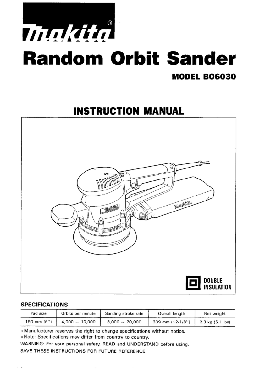
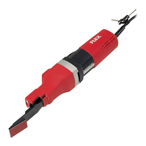
Makita DBO484 User manual

DBO484
EN Cordless Finishing Sander INSTRUCTION MANUAL 7
SV Batteridriven planslipmaskin BRUKSANVISNING 14
NO Batteridrevet nslipemaskin BRUKSANVISNING 21
FI Akkukäyttöinen
viimeistelyhiomakone KÄYTTÖOHJE 28
DA Akku svingsliber BRUGSANVISNING 35
LV Bezvada apdares slīpmašīna LIETOŠANAS INSTRUKCIJA 42
LT Belaidis šlifuotuvas NAUDOJIMO INSTRUKCIJA 49
ET Juhtmeta taldlihvija KASUTUSJUHEND 56
RU
Аккумуляторная
вибрационная
шлифмашина
РУКОВОДСТВО ПО
ЭКСПЛУАТАЦИИ 63

2
1
3
2
Fig.1
1
2
Fig.2
1 2
Fig.3
1
Fig.4
1
2
3
Fig.5
1
2
Fig.6
4
2
1 3
5
4
2
1 3
5
Fig.7

3
2 3
5 4
1
Fig.8
31
2
Fig.9
4
2
13
5
4
2
13
5
Fig.10
2
1
3
Fig.11
1
3
2
Fig.12
1
3
2
Fig.13
1
2
1
Fig.14

4
1
3
2
Fig.15
1
2
1
2
3
1
3
3
Fig.16
1
23
1
2
3
Fig.17
1
2
3
Fig.18
1
Fig.19

5
1
2
3
4
Fig.20
3
1
2
3
Fig.21
1
2
5
4
3
Fig.22
1
2
5
4
3
Fig.23
3
1
2
3
Fig.24
21
4
3
Fig.25

6
Fig.26
Fig.27

7ENGLISH
ENGLISH (Original instructions)
SPECIFICATIONS
Model: DBO484
Pad size Square pad 112 mm x 102 mm
Triangular pad 112 mm x 190 mm
Rectangular pad 112 mm x 168.5 mm
Abrasive paper For square pad (Hook and loop) 114 mm x 102 mm
For square pad (Clamp) 114 mm x 140 mm
For triangular pad Rectangular paper: 114 mm x 102 mm
Triangular paper: 96 mm
For rectangular pad 112 mm x 168.5 mm, 112 mm x 66 mm
Orbits per minute High 14,000 min-1
Low 11,000 min-1
Overall length (with BL1860B) 171 mm
Rated voltage D.C. 18 V
Net weight 1.4 - 1.8 kg
* Thestandardpaddiersfromcountrytocountry.
• Duetoourcontinuingprogramofresearchanddevelopment,thespecicationshereinaresubjecttochange
without notice.
• Specicationsandbatterycartridgemaydierfromcountrytocountry.
• Theweightmaydierdependingontheattachment(s),includingthebatterycartridge.Thelightestandheavi-
est combinations, according to EPTA-Procedure 01/2014, are shown in the table.
Applicable battery cartridge and charger
Batterycartridge BL1815N / BL1820B / BL1830B / BL1840B / BL1850B / BL1860B
Charger DC18RC / DC18RD / DC18RE / DC18SD / DC18SE / DC18SF /
DC18SH / DC18WC
• Someofthebatterycartridgesandchargerslistedabovemaynotbeavailabledependingonyourregionof
residence.
WARNING: Only use the battery cartridges and chargers listed above.Useofanyotherbatterycartridges
andchargersmaycauseinjuryand/orre.
Intended use
Thetoolisintendedforthesandingoflargesurfaceof
wood, plastic and metal materials as well as painted
surfaces.
Noise
ThetypicalA-weightednoiseleveldeterminedaccord-
ing to EN62841-2-4:
Sound pressure level (LpA) : 75 dB(A)
Uncertainty(K):3dB(A)
Thenoiselevelunderworkingmayexceed80dB(A).
NOTE: The declared noise emission value(s) has
been measured in accordance with a standard test
methodandmaybeusedforcomparingonetoolwith
another.
NOTE: The declared noise emission value(s)
mayalsobeusedinapreliminaryassessmentof
exposure.
WARNING: Wear ear protection.
WARNING: The noise emission during actual
use of the power tool can dier from the declared
value(s) depending on the ways in which the
tool is used especially what kind of workpiece is
processed.
WARNING: Be sure to identify safety mea-
sures to protect the operator that are based on an
estimation of exposure in the actual conditions of
use (taking account of all parts of the operating
cycle such as the times when the tool is switched
o and when it is running idle in addition to the
trigger time).
Vibration
The vibration total value (tri-axial vector sum) deter-
mined according to EN62841-2-4:
Work mode: sanding metal plate (square base)
Vibration emission (ah) : 2.5 m/s2or less
Uncertainty(K):1.5m/s2

8ENGLISH
NOTE: The declared vibration total value(s) has been
measured in accordance with a standard test method
andmaybeusedforcomparingonetoolwithanother.
NOTE:Thedeclaredvibrationtotalvalue(s)mayalso
beusedinapreliminaryassessmentofexposure.
WARNING: The vibration emission during
actual use of the power tool can dier from the
declared value(s) depending on the ways in which
the tool is used especially what kind of workpiece
is processed.
WARNING: Be sure to identify safety mea-
sures to protect the operator that are based on an
estimation of exposure in the actual conditions of
use (taking account of all parts of the operating
cycle such as the times when the tool is switched
o and when it is running idle in addition to the
trigger time).
EC Declaration of Conformity
For European countries only
TheECdeclarationofconformityisincludedasAnnexA
to this instruction manual.
SAFETY WARNINGS
General power tool safety warnings
WARNING: Read all safety warnings, instruc-
tions, illustrations and specications provided
with this power tool.Failuretofollowallinstructions
listedbelowmayresultinelectricshock,reand/or
seriousinjury.
Save all warnings and instruc-
tions for future reference.
Theterm"powertool"inthewarningsreferstoyour
mains-operated(corded)powertoolorbattery-operated
(cordless) power tool.
Sander safety warnings
1.
Always use safety glasses or goggles. Ordinary
eye or sun glasses are NOT safety glasses.
2. Hold the tool rmly.
3. Do not leave the tool running. Operate the tool
only when hand-held.
4. This tool has not been waterproofed, so do not
use water on the workpiece surface.
5. Ventilate your work area adequately when you
perform sanding operations.
6. Some material contains chemicals which may
be toxic. Take caution to prevent dust inhala-
tion and skin contact. Follow material supplier
safety data.
7. Use of this tool to sand some products, paints
and wood could expose user to dust contain-
ing hazardous substances. Use appropriate
respiratory protection.
8. Be sure that there are no cracks or breakage
on the pad before use. Cracks or breakage
may cause a personal injury.
9. Watch your footing and maintain your balance
with the tool. Make sure there is no one below
when working in high locations.
SAVE THESE INSTRUCTIONS.
WARNING: DO NOT let comfort or familiarity
with product (gained from repeated use) replace
strict adherence to safety rules for the subject
product. MISUSE or failure to follow the safety
rules stated in this instruction manual may cause
serious personal injury.
Important safety instructions for
battery cartridge
1.
Before using battery cartridge, read all instruc-
tions and cautionary markings on (1) battery
charger, (2) battery, and (3) product using battery.
2. Do not disassemble or tamper with the battery
cartridge.Itmayresultinare,excessiveheat,
or explosion.
3. If operating time has become excessively
shorter, stop operating immediately. It may
result in a risk of overheating, possible burns
and even an explosion.
4.
If electrolyte gets into your eyes, rinse them out
with clear water and seek medical attention right
away. It may result in loss of your eyesight.
5. Do not short the battery cartridge:
(1) Do not touch the terminals with any con-
ductive material.
(2) Avoid storing battery cartridge in a con-
tainer with other metal objects such as
nails, coins, etc.
(3) Do not expose battery cartridge to water
or rain.
A battery short can cause a large current
ow, overheating, possible burns and even a
breakdown.
6. Do not store and use the tool and battery car-
tridge in locations where the temperature may
reach or exceed 50 °C (122 °F).
7. Do not incinerate the battery cartridge even if
it is severely damaged or is completely worn
out. The battery cartridge can explode in a re.
8. Do not nail, cut, crush, throw, drop the battery
cartridge, or hit against a hard object to the
battery cartridge.Suchconductmayresultina
re,excessiveheat,orexplosion.
9. Do not use a damaged battery.
10.
The contained lithium-ion batteries are subject to
the Dangerous Goods Legislation requirements.
Forcommercialtransportse.g.bythirdparties,
forwardingagents,specialrequirementonpack-
aging and labeling must be observed.
Forpreparationoftheitembeingshipped,consultingan
expertforhazardousmaterialisrequired.Pleasealso
observepossiblymoredetailednationalregulations.
Tapeormaskoopencontactsandpackupthe
batteryinsuchamannerthatitcannotmove
around in the packaging.
9ENGLISH
11. When disposing the battery cartridge, remove
it from the tool and dispose of it in a safe
place. Follow your local regulations relating to
disposal of battery.
12. Use the batteries only with the products
specied by Makita. Installing the batteries to
non-compliantproductsmayresultinare,exces-
siveheat,explosion,orleakofelectrolyte.
13. If the tool is not used for a long period of time,
the battery must be removed from the tool.
14. During and after use, the battery cartridge may
take on heat which can cause burns or low
temperature burns. Pay attention to the han-
dling of hot battery cartridges.
15. Do not touch the terminal of the tool imme-
diately after use as it may get hot enough to
cause burns.
16. Do not allow chips, dust, or soil stuck into the
terminals, holes, and grooves of the battery
cartridge.Itmaycauseheating,catchingre,
burstandmalfunctionofthetoolorbatterycar-
tridge,resultinginburnsorpersonalinjury.
17. Unless the tool supports the use near
high-voltage electrical power lines, do not use
the battery cartridge near high-voltage electri-
cal power lines.Itmayresultinamalfunctionor
breakdownofthetoolorbatterycartridge.
18. Keep the battery away from children.
SAVE THESE INSTRUCTIONS.
CAUTION: Only use genuine Makita batteries.
Useofnon-genuineMakitabatteries,orbatteriesthat
havebeenaltered,mayresultinthebatterybursting
causingres,personalinjuryanddamage.Itwill
alsovoidtheMakitawarrantyfortheMakitatooland
charger.
Tips for maintaining maximum
battery life
1. Charge the battery cartridge before completely
discharged. Always stop tool operation and
charge the battery cartridge when you notice
less tool power.
2. Never recharge a fully charged battery car-
tridge. Overcharging shortens the battery
service life.
3. Charge the battery cartridge with room tem-
perature at 10 °C - 40 °C (50 °F - 104 °F). Let
a hot battery cartridge cool down before
charging it.
4. When not using the battery cartridge, remove
it from the tool or the charger.
5. Charge the battery cartridge if you do not use
it for a long period (more than six months).
FUNCTIONAL DESCRIPTION
CAUTION: Always be sure that the tool is
switched o and the battery cartridge is removed
before adjusting or checking function on the tool.
Installing or removing battery cartridge
CAUTION: Always switch o the tool before
installing or removing of the battery cartridge.
CAUTION: Hold the tool and the battery car-
tridge rmly when installing or removing battery
cartridge.Failuretoholdthetoolandthebattery
cartridgermlymaycausethemtoslipoyourhands
andresultindamagetothetoolandbatterycartridge
andapersonalinjury.
►Fig.1: 1. Red indicator 2. Button 3.Batterycartridge
Toremovethebatterycartridge,slideitfromthetool
whileslidingthebuttononthefrontofthecartridge.
Toinstallthebatterycartridge,alignthetongueonthe
batterycartridgewiththegrooveinthehousingandslip
itintoplace.Insertitallthewayuntilitlocksinplace
withalittleclick.Ifyoucanseetheredindicatoras
showninthegure,itisnotlockedcompletely.
CAUTION: Always install the battery cartridge
fully until the red indicator cannot be seen.Ifnot,
itmayaccidentallyfalloutofthetool,causinginjuryto
youorsomeonearoundyou.
CAUTION: Do not install the battery cartridge
forcibly.Ifthecartridgedoesnotslideineasily,itis
notbeinginsertedcorrectly.
Indicating the remaining battery capacity
Only for battery cartridges with the indicator
►Fig.2: 1. Indicator lamps 2. Check button
Pressthecheckbuttononthebatterycartridgetoindi-
catetheremainingbatterycapacity.Theindicatorlamps
lightupforafewseconds.
Indicator lamps Remaining
capacity
Lighted O Blinking
75% to 100%
50% to 75%
25% to 50%
0% to 25%
Charge the
battery.
Thebattery
mayhave
malfunctioned.

10 ENGLISH
NOTE:Dependingontheconditionsofuseandthe
ambienttemperature,theindicationmaydierslightly
fromtheactualcapacity.
NOTE:Therst(farleft)indicatorlampwillblinkwhen
thebatteryprotectionsystemworks.
Tool / battery protection system
Thetoolisequippedwithatool/batteryprotectionsys-
tem.Thissystemautomaticallycutsopowertothe
motortoextendtoolandbatterylife.Thetoolwillauto-
maticallystopduringoperationifthetoolorbatteryis
placedunderoneofthefollowingconditions:
Overload protection
Whenthetoolorbatteryisoperatedinamannerthat
causesittodrawanabnormallyhighcurrent,thetool
automaticallystopswithoutanyindication.Inthissit-
uation,turnthetooloandstoptheapplicationthat
caused the tool to become overloaded. Then turn the
tool on to restart.
Overheat protection
Whenthetoolorbatteryisoverheated,thetoolstops
automatically.Inthiscase,letthetoolandbatterycool
beforeturningthetoolonagain.
Overdischarge protection
Whenthebatterycapacityisnotenough,thetoolstops
automatically.Inthiscase,removethebatteryfromthe
toolandchargethebattery.
Protections against other causes
Protectionsystemisalsodesignedforothercauses
that could damage the tool and allows the tool to stop
automatically.Takeallthefollowingstepstoclearthe
causes,whenthetoolhasbeenbroughttoatemporary
halt or stop in operation.
1. Turnthetoolo,andthenturnitonagainto
restart.
2. Chargethebattery(ies)orreplaceit/themwith
rechargedbattery(ies).
3. Letthetoolandbattery(ies)cooldown.
Ifnoimprovementcanbefoundbyrestoringprotection
system,thencontactyourlocalMakitaServiceCenter.
Switch action
CAUTION: Avoid turning the tool on while it
is placed on the workpiece or on your workbench.
Itmaycausepersonalinjuryordamage.
Turning the tool on and o
Press the power/speed select button to start the tool.
The tool starts to run at its highest orbital speed.
Press the stop button to stop the tool.
►Fig.3: 1. Power/speed select button 2. Stop button
Changing the tool speed
The orbital speed can be changed in two modes; high
and low. Choose either mode depending on the applica-
tion and workload.
Press the power/speed select button to switch speed
mode while the tool is running.
►Fig.4: 1. Power/speed select button
Speed settings table
Speed level Orbital per minute
2 (High) 14,000 min-1 (/min)
1 (Low) 11,000 min-1 (/min)
NOTICE: If the tool is operated continuously
at low speeds for a long time, the motor will get
overloaded, resulting in tool malfunction.
NOTICE: Select an appropriate speed range for
your sanding operations to avoid overheating
and melting the workpiece. Sanding at high orbital
speedmayheatworkpieceandmeltitatthepointof
contact.
ASSEMBLY
CAUTION: Always be sure that the tool is
switched o and the battery cartridge is removed
before carrying out any work on the tool.
Installing and removing abrasive paper
CAUTION: Always make sure that a sheet of
abrasive paper is installed securely before use.
Thepapermayotherwisebeloosened,removed
easilyandsubjecttoslippage,resultinginuneven
sanding operation.
NOTE:Bendingthepaperbeforehandmakesattach-
ment easier.
Using hook-and-loop abrasive paper
CAUTION: Make sure to install a hook-and-
loop pad correctly and securely. A loose attach-
mentwillrunoutofbalanceandcauseanexcessive
vibrationresultinginlossofcontrol.
CAUTION: Be sure that a hook-and-loop pad
and abrasive paper are aligned and securely
attached.
CAUTION: Only use hook-and-loop abrasive
papers. Never use pressure-sensitive abrasive
papers.
1.
Removealldirtandforeignmatterfromthehook-and-looppad.
2. Attachasheetofoptionalhook-and-loopabrasive
paper to the pad, aligning the dust-suction holes in the
paper with those in the pad.
►Fig.5:
1. Abrasive paper 2. Pad 3. Dust-suction holes
3.
Toremovetheabrasivepaper,peelitofromtheedge.

11 ENGLISH
Using abrasive paper without dust-
suction hole
Optional accessory
1. Cutasheetofabrasivepaperdowntoanappro-
priate size.
►Fig.6: 1. Abrasive paper 2. Pad
2. Push and hold down the clamp lever on either
frontorrearendofthepad,andslideitawayfrom
thestoppersotheclampisreleasedfromitslocked
position.
3. Pulltheclampleveroutwardsasfaraspossibleto
createaspacebetweentheclampandsidewallofthe
sandingbaseinwhichoneendofabrasivepapercan
be inserted.
4. Sliponeendoftheabrasivepaperintothespace
between the clamp and sanding base.
5. Repositiontheabrasivepapersoitisnelyover-
laidonthepadsurface.
6. Set the clamp lever back in a locked position to
clamptheendofabrasivepapersecurely.
7. Release the clamp on the other end, and have the
otherendofabrasivepaperreadytobeclamped.
8. Maintainapropertensiononabrasivepaper,and
then set the clamp lever on the other end in a locked
position.
►Fig.7: 1. Abrasive paper 2. Clamp 3. Sanding base
4. Clamp lever 5. Stopper
9. Cover the abrasive paper with the punch plate
withitspositioningstoppersadjacenttothecornerwell
tontotwoofthesideedgesofthepadandsanding
base.
►Fig.8: 1. Abrasive paper 2. Punch plate
3. Positioning stoppers 4. Pad 5. Sanding
base
10. Push the punch plate over the abrasive paper to
make dust-suction holes.
11. To remove the abrasive paper, release the clamps
onbothendsandtakethepaperothepad.
Using abrasive paper with dust-
suction hole
Optional accessory
1. Push and hold down the clamp lever on either
frontorrearendofthepad,andslideitawayfrom
thestoppersotheclampisreleasedfromitslocked
position.
2. Pulltheclampleveroutwardsasfaraspossibleto
createaspacebetweentheclampandsidewallofthe
sandingbaseinwhichoneendofabrasivepapercan
be inserted.
3. Placeasheetofabrasivepaperoverthepad,
aligning the dust-suction holes in the paper with those
in the pad.
►Fig.9: 1. Abrasive paper 2. Pad 3. Dust-suction hole
4. Sliponeendoftheabrasivepaperintothespace
between the clamp and sanding base.
5. Set the clamp lever back in a locked position so
theendofabrasivepaperisclampedsecurely.
6. Release the clamp on the other end, and have the
otherendofabrasivepaperreadytobeclamped.
7.
Maintainapropertensiononabrasivepaper,andthen
set the clamp lever on the other end in a locked position.
►Fig.10: 1. Abrasive paper 2. Clamp 3. Sanding base
4. Clamp lever 5. Stopper
8. To remove the abrasive paper, release the clamps
onbothendsandtakethepaperothepad.
Using triangular/rectangular abrasive
paper
Optional accessory
CAUTION: Make sure to install a hook-and-
loop pad correctly and securely. A loose attach-
mentwillrunoutofbalanceandcauseanexcessive
vibrationresultinginlossofcontrol.
CAUTION: Be sure that a hook-and-loop pad
and abrasive paper are aligned and securely
attached.
CAUTION: Only use hook-and-loop abrasive
papers. Never use pressure-sensitive abrasive
papers.
NOTICE: The cap or the O-ring may come out of
the sanding base while replacing the pad. Be sure
to set the cap or the O-ring back in the circular
hole or the circular groove around the center of
the base before installing the optional pad.
►Fig.11: 1. O-ring 2. Sanding base 3. Circular groove
1. Loosenandremovethefourscrewssecuringthe
pad to the sanding base.
►Fig.12: 1. Screws 2. Pad 3. Sanding base
2. Replace the standard-equipped pad with a trian-
gular/rectangular pad.
3. Re-tightenthescrewsrmlytosecurethetriangu-
lar/rectangular pad.
Triangular pad
►Fig.13:
1. Screws 2. Triangular pad 3. Sanding base
Youcaninstalltheabrasivepaperonthesideofthepad
as illustrated.
►Fig.14: 1. Abrasive paper 2. Pad
Rectangular pad
►Fig.15:
1. Screws 2. Rectangular pad 3. Sanding base
4. Removealldirtandforeignmatterfromthetrian-
gular/rectangular pad.
5. Attachasheetofoptionalhook-and-loopabrasive
paper to the triangular/rectangular pad, aligning the
dust-suction holes in the paper with those in the pad.
Triangular pad
►Fig.16: 1. Abrasive paper 2. Triangular pad 3. Dust-
suction holes
Rectangular pad
►Fig.17: 1. Abrasive paper 2. Rectangular pad
3. Dust-suction holes
6. Toremovetheabrasivepaper,peelitofromthe
edge.

12 ENGLISH
Installing and removing dust bag
Optional accessory
Attach the dust bag over the tapered dust spout at the
backendofthemotorhousing.Putthedustinletofthe
bagontothedustspoutasfarasitwillgotoavoidit
fromcomingoduringoperation.
►Fig.18: 1. Dust spout 2. Dust inlet 3. Dust bag
NOTICE:Donotholdthedustbagwhencarry-
ingthetool.Otherwise,thetoolmayfallandbe
damaged.
NOTE:Toensureoptimaldustcollecting,emptythe
dustbagwhenitbecomeslledtoapproximatelyhalf
ofitscapacity.
Removethedustbagfromthetoolandremovethe
dustnozzle.Thengentlyshakeortapthedustbag
toempty.
►Fig.19: 1. Dust nozzle
Installing and removing dust box
Optional accessory
Attach the dust box over the tapered dust spout at the
backendofthemotorhousing.Putthedustinletonto
thedustspoutasfarasitwillgotoavoiditfromcoming
oduringoperation.
►Fig.20: 1. Dust spout 2. Dust inlet 3. Dust nozzle
4. Dust box
NOTICE:Donotholdthedustboxwhencarry-
ingthetool.Otherwise,thetoolmayfallandbe
damaged.
NOTE:Toensureoptimaldustcollecting,emptythe
dustboxwhenitbecomeslledtoapproximatelyhalf
ofitscapacity.
1. Removethedustboxfromthetool.
2. Detachthedustnozzlefromtheboxwhile
pressing and holding the locking latches on both
sidesofthebox.
3. Gentlyshakeortapthedustboxtoempty.
Replacing paper lter
NOTICE: Be aware to align the logos on all the
dust box, paper lter and dust nozzle in a consis-
tent orientation when reassembling components.
1. Removethedustboxfromthetool.
2. Detachthedustnozzlefromtheboxwhilepress-
ingandholdingthelockinglatchesonbothsidesofthe
box.
►Fig.21: 1. Dust nozzle 2. Dust box 3. Locking latch
3. Holdtheinnertopedgeofthecardboardopening,
andpullitodownwardstodisengagetheoutertop
edgeofthecardboardopeningfromtheupperhooking
tabonthelipofthedustbox.
4. Takethepaperlteroutofthedustboxwhile
pullingtheouterbottomedgeofthecardboardopening
freefromthelowerhookingtab.
►Fig.22: 1.Paperlter2. Cardboard opening
3. Upper hooking tab 4. Lower hooking tab
5. Dust box
5. Replaceapaperlterbyengagingthebottom
edgeofthecardboardopeninginthelowerhooking
tab and push the top edge inwards until it clips into the
upper hooking tab.
►Fig.23: 1.Paperlter2. Cardboard opening
3. Upper hooking tab 4. Lower hooking tab
5. Dust box
6. Snap the dust nozzle into place while pressing
andholdingthelockinglatchesonbothsidesofthedust
box.
►Fig.24: 1. Dust nozzle 2. Dust box 3. Locking latch
Connecting with vacuum cleaner
Optional accessory
Whenyouwishtoperformcleansandingoperation,
connectaMakitavacuumcleanertoyourtool.Use
eitheranoptionalhose28mmoracombinationof
thefrontcu22andhoseprovidedwiththecleanerto
establish a connection.
►Fig.25: 1. Dust spout 2.Frontcu3. Hose
4. Vacuum cleaner
OPERATION
Sanding operation
CAUTION: Always be sure that the workpiece
is secured rmly.
NOTICE: Never run the tool without the abrasive
paper.Youmayseriouslydamagethepad.
NOTICE: Never force the tool. Excessive pressure
maydecreasethesandingeciency,damagethe
abrasivepaperand/orshortentoollife.
Holdthetoolrmly.Turnthetoolonandwaituntilit
attainsfullspeed.Thengentlyplacethetoolonthe
workpiecesurface.Anishingsanderisgenerallyused
toremoveonlyasmallamountofmaterialatatime.
Sincethequalityofthesurfaceismoreimportantthan
theamountofstockremoved,donotbeardownonthe
tool.Keepthebaseushwiththeworkpieceatalltimes.
►Fig.26
Youcansandthematerialwithupperanddownsideof
thepadwhenyousandwiththetriangular/rectangular
pad.Itisconvenientwhenyousandanobjectsuchas
louver.
►Fig.27

13 ENGLISH
MAINTENANCE
CAUTION: Always be sure that the tool is
switched o and the battery cartridge is removed
before attempting to perform inspection or
maintenance.
NOTICE: Never use gasoline, benzine, thinner,
alcohol or the like. Discoloration, deformation or
cracks may result.
To maintain product SAFETY and RELIABILITY,
repairs,anyothermaintenanceoradjustmentshould
beperformedbyMakitaAuthorizedorFactoryService
Centers,alwaysusingMakitareplacementparts.
After use
Wipeothetoolusingadryclothorclothslightlymoist-
enedwithsoapywateratregularintervals.
OPTIONAL
ACCESSORIES
CAUTION: These accessories or attachments
are recommended for use with your Makita tool
specied in this manual.Theuseofanyother
accessoriesorattachmentsmightpresentariskof
injurytopersons.Onlyuseaccessoryorattachment
foritsstatedpurpose.
Ifyouneedanyassistanceformoredetailsregard-
ingtheseaccessories,askyourlocalMakitaService
Center.
• Abrasive paper (hook and loop)
• Abrasive paper (clamp)
• Square pad (hook and loop)
• Square pad (clamp)
• Rectangular pad
• Triangular pad
• Dust bag
• Dust box
• Filter
• Paperlter
• Makitagenuinebatteryandcharger
NOTE:Someitemsinthelistmaybeincludedinthe
toolpackageasstandardaccessories.Theymay
dierfromcountrytocountry.
Other manuals for DBO484
3
Table of contents
Other Makita Sander manuals

Makita
Makita M9204 User manual

Makita
Makita BO4553 User manual

Makita
Makita 9046 User manual

Makita
Makita BO5030 User manual

Makita
Makita BO6050 User manual

Makita
Makita DBO484 User manual

Makita
Makita BO6010 User manual

Makita
Makita BO4900V User manual

Makita
Makita XVP01 User manual

Makita
Makita BO4565 User manual

Makita
Makita BO6040 User manual

Makita
Makita BO3700 Quick start guide

Makita
Makita BO4550 User manual

Makita
Makita BO5041 User manual

Makita
Makita M9204 User manual

Makita
Makita BO3710 User manual

Makita
Makita PW5001C User manual

Makita
Makita 9032 Manual

Makita
Makita 9036 User manual

Makita
Makita DSL800 User manual