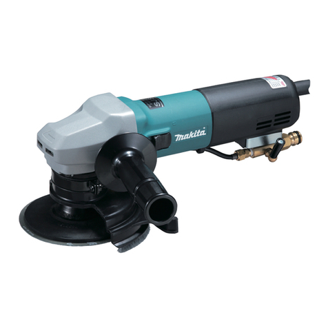
Makita PO5000C User manual

PO5000C
PO6000C
EN Random Orbit Polisher INSTRUCTION MANUAL 4
FR Polisseuse excentrique MANUEL D’ INSTRUCTIONS 9
DE Exzenter-Rotationsschleifer BETRIEBSANLEITUNG 14
IT Lucidatrice rotorbitale ISTRUZIONI PER L’ USO 19
NL Excenter-polijstmachine GEBRUIKSAANW IJZING 24
ES Pulidora de Órbita Excéntrica MANUAL DE
INSTRUCCIONES 29
PT Politriz Rotorbital MANUAL DE INSTRUÇÕ ES 34
DA Excenterpolérmaskine BRUGSANVISNING 39
EL Στιλβωτής τυχαίας τροχιάς ΕΕΙΙΔΙ ΔΗΙΝ 44
TR Titreşimli Polisaj Makinesi KULLANMA KILAVUZU 50

1
2
Fig.1
1
Fig.2
1
Fig.3
1
Fig.4
1
Fig.5
1
2
Fig.6
1
2
Fig.7
2

1
Fig.8
Fig.9
1
Fig.10
3

4ENGLISH
ENGLISH ( Original instructions)
SPECIFICATIONS
Model: PO5000C PO6000C
P ad d iameter 1 25 mm 1 5 0 mm
O rbits per minute 0 - 6 ,8 00 min-1
O v erall length 4 5 1 mm
Net w eigh t 2.8 - 3.0 kg
S af ety c lass /II
•
Due to our continuing program of research and development, the specications herein are subject to change without notice.
Specications may differ from country to country.
• T h e w eigh t may d if f er d epend ing on th e attac h ment( s) . T h e ligh test and h eav iest c ombination, ac c ord ing to
EP T A -P roc ed ure 01 / 201 4 , are sh ow n in th e table.
Intended use
T h e tool is intend ed f or polish ing.
Pow er supply
T h e tool sh ould be c onnec ted only to a pow er supply of
th e same v oltage as ind ic ated on th e nameplate, and
c an only be operated on single-ph ase A C supply . T h ey
are d ouble-insulated and c an, th eref ore, also be used
f rom soc kets w ith out earth w ire.
Noise
T h e ty pic al A -w eigh ted noise lev el d etermined ac c ord -
ing to EN6 28 4 1 :
Model PO5000C
S ound pressure lev el ( L pA ) : 8 1 d B( A )
S ound pow er lev el ( L W A ) : 9 2 d B ( A )
U nc ertainty ( K) : 3 d B( A )
Model PO6000C
S ound pressure lev el ( L pA ) : 8 3 d B( A )
S ound pow er lev el ( L W A ) : 9 4 d B ( A )
U nc ertainty ( K) : 3 d B( A )
NOTE:
T h e d ec lared noise emission v alue( s) h as been
measured in ac c ord anc e w ith a stand ard test meth od
and may be used f or c omparing one tool w ith anoth er.
NOTE:
T h e d ec lared noise emission v alue( s) may
also be used in a preliminary assessment of ex posure.
WARNING: W ear ear protection.
WARNING: The noise emission during actual
use of the pow er tool can differ from the declared
value( s) depending on the w ays in w hich the
tool is used especially w hat kind of w orkpiece is
processed.
WARNING: Be sure to identify safety mea-
sures to protect the operator that are based on an
estimation of exposure in the actual conditions of
use ( taking account of all parts of the operating
cycle such as the times w hen the tool is sw itched
off and w hen it is running idle in addition to the
trigger time) .
Vibration
T h e v ibration total v alue ( tri-ax ial v ec tor sum) d eter-
mined ac c ord ing to EN6 28 4 1 :
Model PO5000C
W ork mod e: polish ing
Vibration emission ( ah , P ) : 6 .5 m/ s2
U nc ertainty ( K) : 1 .5 m/ s2
Model PO6000C
W ork mod e: polish ing
Vibration emission ( ah , P ) : 7.0 m/ s2
U nc ertainty ( K) : 1 .5 m/ s2
NOTE: T h e d ec lared v ibration total v alue( s) h as been
measured in ac c ord anc e w ith a stand ard test meth od
and may be used f or c omparing one tool w ith anoth er.
NOTE: T h e d ec lared v ibration total v alue( s) may also
be used in a preliminary assessment of ex posure.
WARNING: The vibration emission during
actual use of the pow er tool can differ from the
declared value( s) depending on the w ays in w hich
the tool is used especially w hat kind of w orkpiece
is processed.
WARNING: Be sure to identify safety mea-
sures to protect the operator that are based on an
estimation of exposure in the actual conditions of
use ( taking account of all parts of the operating
cycle such as the times w hen the tool is sw itched
off and w hen it is running idle in addition to the
trigger time) .
EC Declaration of Conformity
For European countries only
T h e EC d ec laration of c onf ormity is inc lud ed as A nnex A
to th is instruc tion manual.

5ENGLISH
SAFETY W ARNINGS
General pow er tool safety w arnings
WARNING:
Read all safety w arnings, instruc-
tions, illustrations and specications provided with this
pow er tool. F ailure to f ollow all instruc tions listed below
may result in electric shock, re and/or serious injury.
Save all w arnings and instruc-
tions for future reference.
T h e term " pow er tool" in th e w arnings ref ers to y our
mains-operated ( c ord ed ) pow er tool or battery -operated
( c ord less) pow er tool.
Polisher safety w arnings
1 .
This pow er tool is intended to function as a pol-
isher. Read all safety w arnings, instructions, illus-
trations and specications provided with this power
tool. F ailure to f ollow all instruc tions listed below may
result in electric shock, re and/or serious injury.
2. Operations such as grinding, w ire brushing
or cutting-off are not recommended to be
performed w ith this pow er tool. O perations f or
w h ic h th e pow er tool w as not d esigned may c reate
a hazard and cause personal injury.
3.
Do not use accessories which are not specically
designed and recommended by the tool manufac-
turer. Just bec ause th e ac c essory c an be attac h ed to
y our pow er tool, it d oes not assure saf e operation.
4 . The rated speed of the accessory must be at
least equal to the maximum speed marked on
the pow er tool. A c c essories running f aster th an
their rated speed can break and y apart.
5 .
Threaded mounting of accessories must match
the spindle thread. For accessories mounted
by anges, the arbour hole of the accessory
must t the locating diameter of the ange.
A c c essories th at d o not matc h th e mounting
h ard w are of th e pow er tool w ill run out of balanc e,
v ibrate ex c essiv ely and may c ause loss of c ontrol.
6 .
Do not use a damaged accessory. Before each
use inspect the accessory such as backing pad
for cracks, tear or excess w ear. If pow er tool or
accessory is dropped, inspect for damage or
install an undamaged accessory. After inspecting
and installing an accessory, position yourself and
bystanders aw ay from the plane of the rotating
accessory and run the pow er tool at maximum
no-load speed for one minute. D amaged ac c esso-
ries w ill normally break apart d uring th is test time.
7.
W ear personal protective equipment.
Depending on application, use face shield,
safety goggles or safety glasses. As appropri-
ate, w ear dust mask, hearing protectors, gloves
and w orkshop apron capable of stopping small
abrasive or w orkpiece fragments. T h e ey e pro-
tection must be capable of stopping ying debris
generated by v arious operations. T h e d ust mask
or respirator must be capable of ltrating particles
generated by y our operation. P rolonged ex posure
to h igh intensity noise may c ause h earing loss.
8 .
Keep bystanders a safe distance aw ay from w ork
area. Anyone entering the w ork area must w ear
personal protective equipment. F ragments of
workpiece or of a broken accessory may y away and
cause injury beyond immediate area of operation.
9 . Position the cord clear of the spinning acces-
sory. I f y ou lose c ontrol, th e c ord may be c ut or
snagged and y our h and or arm may be pulled into
th e spinning ac c essory .
1 0. Never lay the pow er tool dow n until the acces-
sory has come to a complete stop. T h e spinning
ac c essory may grab th e surf ac e and pull th e
pow er tool out of y our c ontrol.
1 1 . Do not run the pow er tool w hile carrying it at
your side. A c c id ental c ontac t w ith th e spinning
ac c essory c ould snag y our c loth ing, pulling th e
ac c essory into y our bod y .
1 2. Regularly clean the pow er tool’ s air vents. T h e
motor’ s f an w ill d raw th e d ust insid e th e h ousing
and ex c essiv e ac c umulation of pow d ered metal
may c ause elec tric al h az ard s.
1 3. Do not operate the power tool near ammable
materials. S parks c ould ignite th ese materials.
14. Do not use accessories that require liquid
coolants. U sing w ater or oth er liq uid c oolants
may result in elec troc ution or sh oc k.
Kickback and Related W arnings
Kic kbac k is a sud d en reac tion to a pinc h ed or snagged
rotating w h eel, bac king pad , brush or any oth er ac c es-
sory . P inc h ing or snagging c auses rapid stalling of th e
rotating ac c essory w h ic h in turn c auses th e unc on-
trolled pow er tool to be f orc ed in th e d irec tion opposite
of th e ac c essory ’ s rotation at th e point of th e bind ing.
F or ex ample, if an abrasiv e w h eel is snagged or
pinc h ed by th e w orkpiec e, th e ed ge of th e w h eel th at is
entering into th e pinc h point c an d ig into th e surf ac e of
th e material c ausing th e w h eel to c limb out or kic k out.
The wheel may either jump toward or away from the
operator, d epend ing on d irec tion of th e w h eel’ s mov e-
ment at th e point of pinc h ing. A brasiv e w h eels may also
break und er th ese c ond itions.
Kic kbac k is th e result of pow er tool misuse and / or
inc orrec t operating proc ed ures or c ond itions and c an be
av oid ed by taking proper prec autions as giv en below .
1 . Maintain a rm grip on the power tool and
position your body and arm to allow you to
resist kickback forces. Alw ays use auxiliary
handle, if provided, for maximum control over
kickback or torque reaction during start-up.
T h e operator c an c ontrol torq ue reac tions or kic k-
bac k f orc es, if proper prec autions are taken.
2. Never place your hand near the rotating acces-
sory. A c c essory may kic kbac k ov er y our h and .
3. Do not position your body in the area w here
pow er tool w ill move if kickback occurs.
Kic kbac k w ill propel th e tool in d irec tion opposite
to th e w h eel’ s mov ement at th e point of snagging.
4 . Use special care w hen w orking corners, sharp
edges etc. Avoid bouncing and snagging the
accessory. C orners, sh arp ed ges or bounc ing
h av e a tend enc y to snag th e rotating ac c essory
and c ause loss of c ontrol or kic kbac k.
5 . Do not attach a saw chain w oodcarving blade
or toothed saw blade. S uc h blad es c reate f re-
q uent kic kbac k and loss of c ontrol.

6ENGLISH
Safety Warnings Specic for Polishing Operations
1 .
Do not allow any loose portion of the polishing
bonnet or its attachment strings to spin freely.
Tuck aw ay or trim any loose attachment strings.
L oose and spinning attac h ment strings c an entan-
gle your ngers or snag on the workpiece.
Additional Safety W arnings
1 . Do not leave the tool running. Operate the tool
only w hen hand-held.
2.
Check that the w orkpiece is properly supported.
3.
If w orking place is extremely hot and humid, or
badly polluted by conductive dust, use a short-cir-
cuit breaker ( 30 mA) to assure operator safety.
4 . Do not use the tool on any materials contain-
ing asbestos.
SAVE THESE INSTRUCTIONS.
WARNING: DO NOT let comfort or familiarity
w ith product ( gained from repeated use) replace
strict adherence to safety rules for the subject
product. MISUSE or failure to follow the safety
rules stated in this instruction manual may cause
serious personal injury.
FUNCTIONAL
DESCRIPTION
CAUTION: Alw ays be sure that the tool is
sw itched off and unplugged before adjusting or
checking function on the tool.
Sw itch action
CAUTION: Before plugging in the tool, alw ays
check to see that the sw itch trigger actuates
properly and returns to the " OFF" position w hen
released.
Fig.1: 1. S w itc h trigger 2. L oc k button
T o start th e tool, simply pull th e sw itc h trigger. T h e
rotation speed w ill inc rease as y ou pull th e trigger.
R elease th e sw itc h trigger to stop. F or c ontinuous oper-
ation, pull th e sw itc h trigger, push in th e loc k button and
th en release th e sw itc h trigger. T o stop th e tool f rom th e
loc ked position, pull th e trigger f ully , th en release it.
CAUTION: Sw itch can be locked in " ON" posi-
tion for ease of operator comfort during extended
use. Apply caution w hen locking tool in " ON"
position and maintain rm grasp on tool.
CAUTION: Do not plug in the tool w ith the
lock-on sw itch engaged. T h e tool w ill be run
unsupported and it may cause a personal injury or
breakage.
Speed adjusting dial
Fig.2: 1. Speed adjusting dial
T h e rotating speed c an be c h anged by turning th e
speed adjusting dial to a given number setting from to
5 . H igh er speed is obtained w h en th e d ial is turned in
th e d irec tion of number 5 . A nd low er speed is obtained
w h en it is turned in th e d irec tion of number 1 .
R ef er to th e table f or th e relationsh ip betw een th e number
settings on th e d ial and th e approx imate rotating speed .
Number Orbits per min. Pad rotating
speed per minute
in random orbit
w ith forced rota-
tion mode
11 ,6 00 1 8 0
22,5 00 29 0
33,700 4 30
45 ,300 6 1 0
56 ,8 00 78 0
NOTICE: If the tool is operated continuously
at low speeds for a long time, the motor w ill get
overloaded, resulting in tool malfunction.
NOTICE: The speed adjusting dial can be turned
only as far as 5 and back to 1. Do not force it past
5 or 1, or the speed adjusting function may no
longer w ork.
Electronic function
T h e tools eq uipped w ith elec tronic f unc tion are easy to
operate bec ause of th e f ollow ing f eatures.
Constant speed control
Possible to get ne nish, because the rotating speed is
kept c onstant ev en und er th e load ed c ond ition.
Soft start feature
S of t start bec ause of suppressed starting sh oc k.
Selecting the action mode
T urn th e c h ange knob to alter th e rotation mod e.
Fig.3: 1. C h ange knob
NOTICE: Alw ays turn the knob fully. If the knob
is in the middle position, you cannot turn on the
tool.
NOTICE: You cannot change the action mode
w hen the tool is sw itched on.
Random orbit w ith forced rotation
mode
Fig.4: 1. C h ange knob
R and om orbit w ith f orc ed rotation mod e is orbital ac tion
w ith f orc ed rotation of th e pad f or rough polish ing suc h
as surf ac e treatment.
R otate th e c h ange knob c ounterc loc kw ise f or rand om
orbit w ith f orc ed rotation mod e.

7ENGLISH
Random orbit mode
Fig.5: 1. C h ange knob
R and om orbit mod e is orbital ac tion w ith f ree rotation of
the pad for ne polishing.
R otate th e c h ange knob c loc kw ise f or rand om orbit
mod e.
ASSEMBLY
CAUTION: Alw ays be sure that the tool is
sw itched off and unplugged before carrying out
any w ork on the tool.
Installing the backing pad
Fig.6: 1. Bac king pad 2. H ex w renc h
P ut th e bac king pad on th e sh af t th en turn th e bolt
c loc kw ise w ith a h ex w renc h .
CAUTION: Make sure that the backing pad is
secured properly. L oose attac h ment w ill run out of
balanc e and c ause a ex c essiv e v ibration w h ic h may
c ause loss of c ontrol.
Installing side grip
Optional accessory
Fig.7: 1. C ap 2. S id e grip
R emov e th e c ap and sc rew th e sid e grip on th e tool
sec urely .
T h e sid e grip c an be installed on eith er sid e of th e tool.
Installing or removing pad
Optional accessory
CAUTION: Only use hook-and-loop system
pads for polishing.
Fig.8: 1. P ad
To install the pad, rst remove all dirt and foreign mat-
ter f rom th e h ook-and -loop sy stem of th e pad and th e
bac king pad . A ttac h th e pad to th e bac king pad so th at
th eir ed ges are aligned .
To remove the pad from the backing pad, just pull up
f rom its ed ge.
CAUTION: Make sure that the pad and
backing pad are aligned and securely attached.
O th erw ise th e pad w ill c ause an ex c essiv e v ibration
w h ic h may c ause loss of c ontrol or th e pad may be
th row n out f rom th e tool.
OPERATION
CAUTION: Only use Makita genuine pads for
polishing.
CAUTION: Make sure the w ork material is
secured and stable. Falling object may cause
personal injury.
CAUTION: Hold the tool rmly with one hand
on the sw itch handle and the other hand on the
front grip ( or side handle) w hen performing the
tool.
CAUTION: Do not run the tool at high load
over an extended time period. I t may result in tool
malfunction which causes electric shock, re and/or
serious injury.
CAUTION: Be careful not to touch the rotating
part.
NOTICE: Never force the tool. Ex c essiv e pressure
may lead to decreased polishing efciency, damaged
pad , or sh orten tool lif e.
NOTICE: Continuous operation at high speed
may damage w ork surface.
Polishing operation
Fig.9
1. S urf ac e treatment ( R and om orbit w ith f orc ed
rotation mod e)
Use a wool pad for rough nishing then use a sponge
pad for ne nishing.
2. A pply ing w ax ( R and om orbit mod e)
U se a sponge pad . A pply w ax to th e sponge pad or w ork
surf ac e. R un th e tool at low speed to smooth out w ax .
CAUTION: Do not apply excessive w ax or
polishing agent. I t w ill generate more d ust and may
c ause ey e or respiratory d iseases.
NOTE: F irst, perf orm a test w ax ing on an inc onspic -
uous portion of th e w ork surf ac e. Make sure th at th e
tool w ill not sc ratc h th e surf ac e or result in unev en
w ax ing bef ore.
3. R emov ing w ax ( R and om orbit mod e)
U se anoth er sponge pad . R un th e tool to remov e w ax .
4. P olish ing ( R and om orbit mod e)
A pply a f elt pad gently to th e w ork surf ac e.
MAINTENANCE
CAUTION: Alw ays be sure that the tool is
sw itched off and unplugged before attempting to
perform inspection or maintenance.
NOTICE: Never use gasoline, benzine, thinner,
alcohol or the like. Discoloration, deformation or
cracks may result.

8ENGLISH
Cleaning dust covers
Fig.10: 1. D ust c ov er
R egularly c lean th e d ust c ov ers on th e inh alation v ents
f or smooth air c irc ulation. R emov e th e d ust c ov ers and
c lean th e mesh .
T o maintain prod uc t S A F ET Y and R EL I A BI L I T Y , repairs,
c arbon brush inspec tion and replac ement, any oth er
maintenance or adjustment should be performed by
Makita A uth oriz ed or F ac tory S erv ic e C enters, alw ay s
using Makita replac ement parts.
OPTIONAL
ACCESSORIES
CAUTION: These accessories or attachments
are recommended for use w ith your Makita tool
specied in this manual. T h e use of any oth er
ac c essories or attac h ments migh t present a risk of
injury to persons. Only use accessory or attachment
f or its stated purpose.
I f y ou need any assistanc e f or more d etails regard -
ing th ese ac c essories, ask y our loc al Makita S erv ic e
C enter.
• S id e grip
• Bac king pad
• W ool pad
• S ponge pad
• F elt pad
NOTE: S ome items in th e list may be inc lud ed in th e
tool pac kage as stand ard ac c essories. T h ey may
d if f er f rom c ountry to c ountry .

9FRANÇAIS
FRANÇAIS ( Instructions originales)
SPÉ CIFICATIONS
Modè le : PO5000C PO6000C
D iamè tre d u plateau 1 25 mm 1 5 0 mm
Nombre d ’ osc illations par minute 0 à 6 8 00 min-1
L ongueur totale 4 5 1 mm
P oid s net 2,8 - 3,0 kg
C até gorie d e sé c urité /II
tant donné l’évolution constante de notre programme de recherche et de développement, les spécications
contenues dans ce manuel sont sujettes à modication sans préavis.
Les spécications peuvent varier suivant les pays.
• L e poid s peut ê tre d if f é rent selon les ac c essoires. L es assoc iations la plus lé gè re et la plus lourd e, c onf ormé -
ment à la proc é d ure EP T A 01 / 201 4 , sont ind iq ué es d ans le tableau.
Utilisations
L ’ outil est c onç u pour polir.
Alimentation
L ’ outil ne d ev ra ê tre rac c ord é q u’ à une alimentation d e la
mme tension que celle qui gure sur la plaque signalé-
tiq ue, et il ne pourra f onc tionner q ue sur un c ourant sec teur
monoph asé . R é alisé av ec une d ouble isolation, il peut d e
c e f ait ê tre alimenté par une prise sans mise à la terre.
Bruit
Niv eau d e bruit pond é ré A ty piq ue, d é terminé selon EN6 28 4 1 :
Modè le PO5000C
Niv eau d e pression sonore ( L pA ) : 8 1 d B ( A )
Niv eau d e puissanc e sonore ( L W A ) : 9 2 d B ( A )
I nc ertitud e ( K) : 3 d B ( A )
Modè le PO6000C
Niv eau d e pression sonore ( L pA ) : 8 3 d B ( A )
Niv eau d e puissanc e sonore ( L W A ) : 9 4 d B ( A )
I nc ertitud e ( K) : 3 d B ( A )
NOTE : L a ou les v aleurs d ’ é mission d e bruit d é c la-
ré es ont é té mesuré es c onf ormé ment à la mé th od e
d e test stand ard et peuv ent ê tre utilisé es pour c om-
parer les outils entre eux .
NOTE : L a ou les v aleurs d ’ é mission d e bruit d é c la-
ré es peuv ent aussi ê tre utilisé es pour l’ é v aluation
pré liminaire d e l’ ex position.
AVERTISSEMENT :
Portez un serre-tê te antibruit.
AVERTISSEMENT :
L’ émission de bruit lors de
l’ usage réel de l’ outil électrique peut ê tre différente de la
ou des valeurs déclarées, suivant la façon dont l’ outil est
utilisé, particuliè rement selon le type de piè ce usinée.
AVERTISSEMENT :
Les mesures de sécurité à
prendre pour protéger l’ utilisateur doivent ê tre basées
sur une estimation de l’ exposition dans des condi-
tions réelles d’ utilisation ( en tenant compte de toutes
les composantes du cycle d’ utilisation, comme par
exemple le moment de sa mise hors tension, lorsqu’ il
tourne à vide et le moment de son déclenchement) .
Vibrations
Valeur totale d e v ibrations ( somme d e v ec teur triax ial)
d é terminé e selon EN6 28 4 1 :
Modè le PO5000C
Mod e d e trav ail : polissage
É mission d e v ibrations ( ah , P ) : 6 ,5 m/ s2
I nc ertitud e ( K) : 1 ,5 m/ s2
Modè le PO6000C
Mod e d e trav ail : polissage
É mission d e v ibrations ( ah , P ) : 7,0 m/ s2
I nc ertitud e ( K) : 1 ,5 m/ s2
NOTE : L a ou les v aleurs d e v ibration totales d é c la-
ré es ont é té mesuré es c onf ormé ment à la mé th od e
d e test stand ard et peuv ent ê tre utilisé es pour c om-
parer les outils entre eux .
NOTE : L a ou les v aleurs d e v ibration totales d é c la-
ré es peuv ent aussi ê tre utilisé es pour l’ é v aluation
pré liminaire d e l’ ex position.
AVERTISSEMENT : L’ émission de vibrations
lors de l’ usage réel de l’ outil électrique peut ê tre
différente de la ou des valeurs déclarées, suivant
la façon dont l’ outil est utilisé, particuliè rement
selon le type de piè ce usinée.
AVERTISSEMENT : Les mesures de sécurité
à prendre pour protéger l’ utilisateur doivent ê tre
basées sur une estimation de l’ exposition dans
des conditions réelles d’ utilisation ( en tenant
compte de toutes les composantes du cycle
d’ utilisation, comme par exemple le moment de
sa mise hors tension, lorsqu’ il tourne à vide et le
moment de son déclenchement) .
Déclaration de conformité CE
Pour les pays européens uniquement
L a d é c laration d e c onf ormité C E est f ournie en A nnex e
A à c e mod e d ’ emploi.

10 FRANÇAIS
CONSIGNES DE SÉ CURITÉ
Consignes de sécurité générales
pour outils électriques
AVERTISSEMENT : Veuillez lire les
consignes de sécurité, instructions, illustrations
et spécications ui accompagnent cet outil
électrique. L e non-respec t d e toutes les instruc tions
ind iq ué es c i-d essous peut entraî ner une é lec troc u-
tion, un inc end ie et/ ou d e grav es blessures.
Conservez toutes les mises en garde et
instructions pour référence ultérieure.
L e terme « outil é lec triq ue » d ans les av ertissements
f ait ré f é renc e à l’ outil é lec triq ue alimenté par le sec teur
( av ec c ord on d ’ alimentation) ou à l’ outil é lec triq ue f onc -
tionnant sur batterie ( sans c ord on d ’ alimentation) .
Consignes de sécurité pour polisseuse
1 . Cet outil électrique est conçu pour fonctionner
comme polisseuse. Veuillez lire les consignes
de sécurité, instructions, illustrations et spé-
cications ui accompagnent cet outil élec-
trique. L e non-respec t d e toutes les instruc tions
ind iq ué es c i-d essous peut entraî ner une é lec tro-
c ution, un inc end ie et/ ou d e grav es blessures.
2. Il n’ est pas recommandé de meuler, d’ effectuer
un brossage métallique ou de tronçonner avec
cet outil électrique. L ’ ex é c ution d ’ opé rations
pour lesq uelles l’ outil é lec triq ue n’ a pas é té c onç u
est d angereuse et peut entraî ner d es blessures.
3.
N’ utilisez pas d’ accessoires qui n’ ont pas été conçus
spéciuement et recommandés par le fabricant de lou-
til. Mme si un accessoire peut tre xé sur l’outil électrique,
c ela ne garantit pas q u’ il f onc tionnera d e maniè re sû re.
4 .
La vitesse nominale de l’ accessoire doit ê tre au
moins égale à la vitesse maximum inscrite sur l’ outil
électrique. L es ac c essoires tournant plus v ite q ue leur
v itesse nominale peuv ent se c asser et v oler en é c lats.
5 .
Le letage des accessoires monter doit cor-
respondre à celui de l’ axe. Pour les accessoires
montés laide de asues, la taille de lalésage
de l’ accessoire doit correspondre au diamè tre de
centrage du asue. D es ac c essoires inad apté s
au maté riel d e montage d e l’ outil é lec triq ue pré sen-
teront un d é sé q uilibre et d es v ibrations ex c essiv es,
et risq uent d ’ entraî ner une perte d e c ontrô le.
6 .
N’ utilisez pas l’ accessoire s’ il est endommagé.
Avant chaque utilisation, inspectez les acces-
soires tels ue le plateau de support, pour vérier
labsence de ssures, de déchirures ou dune
usure excessive. Si vous lâ chez l’ outil électrique
ou un accessoire, assurez-vous qu’ il n’ est pas
endommagé ou bien remplacez l’ accessoire
endommagé. Aprs avoir vérié et posé un acces-
soire, assurez-vous que personne, y compris
vous-mê me, ne se trouve dans la trajectoire de
l’ accessoire en rotation et faites tourner l’ outil
électrique à la vitesse à vide maximale pendant
une minute. L es ac c essoires end ommagé s se brisent
gé né ralement au c ours d e c ette pé riod e d ’ essai.
7. Portez un équipement de protection indivi-
duelle. Suivant le type de travail à effectuer,
utilisez un écran facial, des lunettes à coques
ou des lunettes de sécurité. Si nécessaire,
portez un masque anti-poussiè re, des pro-
tè ge-tympans, des gants et un tablier de travail
pouvant arrê ter les particules abrasives ou les
fragments de piè ce. L a protec tion oc ulaire d oit
pouv oir arrê ter les d é bris v olants prod uits par les
d iv erses opé rations. L e masq ue anti-poussiè res
ou le masque ltrant doit pouvoir ltrer les parti-
c ules gé né ré es lors d es trav aux . U ne ex position
prolongé e à un bruit d ’ intensité é lev é e peut entraî -
ner une perte aud itiv e.
8 . Assurez-vous que les passants demeurent à
une distance sû re de la zone de travail. Toute
personne pénétrant dans la zone de travail
doit porter un équipement de protection indivi-
duelle. D es f ragments d e piè c e ou un ac c essoire
cassé peuvent tre éjectés et blesser les per-
sonnes au-d elà d e la z one immé d iate d e trav ail.
9 . Placez le cordon à l’ écart de l’ accessoire
en rotation. En c as d e perte d e maî trise, v ous
risq uez , en c oupant ou en ac c roc h ant le c ord on,
d ’ av oir la main ou le bras attiré v ers l’ ac c essoire
en rotation.
1 0. Ne déposez jamais l’ outil électrique avant que
l’ accessoire ne se soit parfaitement arrê té.
L ’ ac c essoire en rotation peut ac c roc h er la surf ac e
et projeter l’outil électrique de telle sorte que vous
en perd iez la maî trise.
1 1 . Ne transportez pas l’ outil électrique tout en le
laissant tourner. En c as d e c ontac t ac c id entel
av ec l’ ac c essoire en rotation, c e d ernier risq ue
d ’ ac c roc h er v os v ê tements et d ’ ê tre entraî né v ers
v otre c orps.
1 2. Nettoyez régulirement les orices daération
de l’ outil électrique. L e v entilateur d u moteur
aspire la poussiè re à l’ inté rieur d u c arter, c e q ui
pré sente un d anger é lec triq ue en c as d ’ ac c umula-
tion ex c essiv e d e poussiè res mé talliq ues.
1 3. N’ utilisez pas l’ outil électrique prè s de maté-
riaux inammables. L es é tinc elles risq ueraient
d’enammer ces matériaux.
14. N’ utilisez pas d’ accessoires nécessitant un
liquide de refroidissement. L ’ utilisation d ’ eau
ou d ’ un liq uid e d e ref roid issement c omporte un
risq ue d ’ é lec troc ution ou d e c h oc é lec triq ue.
Mises en garde concernant le choc en retour et
autres dangers
L e c h oc en retour est une ré ac tion soud aine q ui sur-
v ient lorsq ue la meule, la semelle, la brosse ou un autre
ac c essoire en rotation se c oinc e ou ac c roc h e. L orsq ue
l’ ac c essoire en rotation se c oinc e ou ac c roc h e, il s’ ar-
rê te soud ainement et l’ utilisateur perd alors la maî trise
de l’outil électrique projeté dans le sens contraire de sa
rotation au point où il se c oinc e d ans la piè c e.
P ar ex emple, si une meule abrasiv e ac c roc h e ou se
c oinc e d ans la piè c e, son tranc h ant introd uit au point
d e pinc ement risq ue d ’ y c reuser la surf ac e d u maté riau,
entraî nant la sortie ou le d é c h aussement d e la meule.
La meule peut alors dévier de sa trajectoire, vers l’uti-
lisateur ou d ans le sens opposé , selon la d irec tion d u
mouv ement d e la meule au point d e pinc ement. D ans
c es c ond itions, la meule abrasiv e risq ue é galement d e
se briser.

11 FRANÇAIS
L e c h oc en retour est le ré sultat d ’ une utilisation inc or-
rec te d e l’ outil é lec triq ue et/ ou d e l’ inobserv ation d es
proc é d ures ou c ond itions d ’ utilisation. I l peut ê tre é v ité en
prenant les pré c autions ad é q uates ind iq ué es c i-d essous.
1 .
Maintenez une poigne ferme sur l’ outil électrique
et placez corps et bras de façon à pouvoir résis-
ter à la force exercée par les chocs en retour.
Utilisez toujours la poignée auxiliaire, s’ il y en a
une, pour avoir une maî trise maximale de l’ outil
en cas de choc en retour ou de force de réaction
exercée au moment du démarrage. L ’ utilisateur
peut maî triser les f orc es d e ré ac tion ou d e c h oc en
retour s’ il prend les pré c autions ad é q uates.
2. Ne placez jamais la main prè s d’ un accessoire
en rotation. L ’ ac c essoire risq uerait d e passer sur
v otre main en c as d e c h oc en retour.
3. Ne vous placez pas dans la zone vers laquelle
l’ outil électrique se déplacera en cas de choc
en retour. Le choc en retour projettera l’outil dans
le sens opposé au mouv ement d e la meule au
point où elle ac c roc h e d ans la piè c e.
4 . Soyez tout particuliè rement prudent lorsque
vous travaillez sur les coins, les arê tes vives,
etc. É vitez de laisser l’ accessoire sautiller ou
accrocher. L ’ ac c essoire en rotation a tend anc e
à ac c roc h er d ans les c oins, sur les arê tes v iv es
ou lorsq u’ il sautille, c e q ui c omporte un risq ue d e
perte d e maî trise ou d e c h oc en retour.
5 . Ne xez pas une chane de coupe, une lame
sculpter le bois ou une lame de scie dentée. D e
telles lames c ausent f ré q uemment d es c h oc s en
retour et d es pertes d e maî trise.
Consignes de sécurité propres aux travaux de polissage
1 . É vitez de laisser tourner librement toute partie
de la peau de polissage ou lexcédent des ls
qui la retiennent. Cachez ou coupez tout excé-
dent de l. En tournant, l’excédent de l risquerait
d e s’ enc h ev ê trer autour d e v os d oigts ou d ’ ac c ro-
c h er la piè c e à trav ailler.
Consignes de sécurité supplémentaires
1 . Ne vous éloignez pas de l’ outil quand il fonc-
tionne. Ne faites fonctionner l’ outil que lorsque
vous le tenez en main.
2. Assurez-vous que la piè ce est correctement
soutenue.
3. Si le site de travail est extrê mement chaud et
humide ou s’ il y a beaucoup de poussiè res
conductrices dans l’ air, utilisez un coupe-cir-
cuit ( 30 mA) pour assurer votre sécurité.
4 . N’ utilisez l’ outil sur aucun matériau contenant
de l’ amiante.
CONSERVEZ CES
INSTRUCTIONS.
AVERTISSEMENT : NE vous laissez PAS
tromper au l dune utilisation répétée par un
sentiment d’ aisance et de familiarité avec le
produit, en négligeant le respect rigoureux des
consignes de sécurité qui accompagnent le pro-
duit en question. La MAUVAISE UTILISATION de
l’ outil ou l’ ignorance des consignes de sécurité
indiquées dans ce mode d’ emploi peut entraî ner
de graves blessures.
DESCRIPTION DU
FONCTIONNEMENT
ATTENTION : Assurez-vous toujours que
l’ outil est hors tension et débranché avant de
lajuster ou de vérier son fonctionnement.
Fonctionnement de la gâ chette
ATTENTION :
Avant de brancher l’ outil, assu-
rez-vous toujours que la gâ chette fonctionne correcte-
ment et revient en position d’ arrê t une fois relâ chée.
Fig.1: 1. G â c h ette 2. Bouton d e v errouillage
Il suft d’enclencher la gchette pour démarrer l’ou-
til. L a v itesse d e rotation augmentera à mesure q ue
v ous enf onc ez la gâ c h ette. P our l’ arrê ter, relâ c h ez la
gâ c h ette. P our un f onc tionnement c ontinu, enc lenc h ez
la gâ c h ette et poussez le bouton d e v errouillage, puis
relâ c h ez la gâ c h ette. P our arrê ter l’ outil en position v er-
rouillé e, enc lenc h ez à f ond la gâ c h ette puis relâ c h ez -la.
ATTENTION :
Vous pouvez verrouiller l’ in-
terrupteur sur la position « Marche » pour plus de
confort en cas d’ utilisation prolongée. Soyez pru-
dent lorsque vous verrouillez l’ outil sur la position
« Marche » , et gardez une prise ferme sur l’ outil.
ATTENTION : Ne branchez pas l’ outil alors
que l’ interrupteur de verrouillage est enclenché.
L ’ outil f onc tionnera sans ê tre soutenu, c e q ui pré -
sente un risq ue d e blessure ou d e rupture.
Cadran de réglage de la vitesse
Fig.2: 1. C ad ran d e ré glage d e la v itesse
La vitesse de rotation peut tre modiée en tournant le cadran de
ré glage d e la v itesse sur un numé ro d e ré glage d onné , d e 1 à 5 .
U ne v itesse plus é lev é e est obtenue lorsq ue le c ad ran est tourné
en d irec tion d u numé ro 5 . T and is q u’ une v itesse moins é lev é e est
obtenue lorsq ue le c ad ran est tourné en d irec tion d u numé ro 1 .
R eportez -v ous au tableau pour le rapport entre les ré glages
numé roté s sur le c ad ran et la v itesse approx imativ e d e rotation.
Numéro Nombre d’ oscilla-
tions par minute
Vitesse de rota-
tion du plateau par
minute en mode
excentrique à
rotation forcée
11 6 00 180
22 5 00 29 0
33 700 4 30
45 300 610
56 8 00 78 0
REMARQUE :
Si l’ outil est utilisé de maniè re continue
à vitesse basse sur une période prolongée, le moteur
surchauffera, entraî nant un dysfonctionnement de l’ outil.
REMARQUE :
Le cadran de réglage de la vitesse ne
peut pas ê tre tourné plus haut que 5 ou plus bas que 1.
N’ essayez pas de le placer au-delà de 5 ou en dessous de 1,
sinon le réglage de la vitesse risque de ne plus fonctionner.

12 FRANÇAIS
Fonctions électroniques
L es c arac té ristiq ues suiv antes f ac ilitent l’ utilisation d es
outils munis d e f onc tions é lec troniq ues.
Commande de vitesse constante
Permet d’obtenir une nition précise puisque la vitesse de rota-
tion est maintenue c onstante mê me en c ond ition d e c h arge.
Fonction de démarrage en douceur
L a suppression d u c h oc d e d é marrage permet un
d é marrage en d ouc eur.
Sélection du mode de fonctionnement
Tournez le bouton de changement pour modier le
mod e d e rotation.
Fig.3: 1. Bouton d e c h angement
REMARQUE : Tournez toujours le bouton à
fond. Si le bouton est sur la position intermé-
diaire, l’ outil ne peut pas ê tre mis sous tension.
REMARQUE : Il est impossible de changer le
mode de fonctionnement lorsque l’ outil est sous
tension.
Mode excentrique à rotation forcée
Fig.4: 1. Bouton d e c h angement
L e mod e ex c entriq ue à rotation f orc é e c onsiste en une
c ourse orbitale av ec rotation f orc é e d u plateau pour un
polissage grossier, c omme le traitement d e surf ac e.
T ournez le bouton d e c h angement d ans le sens inv erse
d es aiguilles d ’ une montre pour le mod e ex c entriq ue à
rotation f orc é e.
Mode excentrique
Fig.5: 1. Bouton d e c h angement
L e mod e ex c entriq ue c onsiste en une c ourse orbitale
avec rotation libre du plateau pour un polissage n.
T ournez le bouton d e c h angement d ans le sens d es
aiguilles d ’ une montre pour le mod e ex c entriq ue.
ASSEMBLAGE
ATTENTION : Avant d’ effectuer toute inter-
vention sur l’ outil, assurez-vous toujours qu’ il est
hors tension et débranché.
Pose du plateau de support
Fig.6: 1. P lateau d e support 2. C lé h ex agonale
P lac ez le plateau d e support sur l’ arbre, puis tournez
le boulon d ans le sens d es aiguilles d ’ une montre av ec
une c lé h ex agonale.
ATTENTION : Assurez-vous que le plateau de
support est solidement xé. Une mauvaise xation
entraî nera un d é sé q uilibre et d es v ibrations ex c es-
siv es, c e q ui peut prov oq uer une perte d e c ontrô le.
Installation de la poignée latérale
Accessoire en option
Fig.7: 1. C apuc h on 2. P oigné e laté rale
R etirez le c apuc h on et v issez solid ement la poigné e
laté rale sur l’ outil.
L a poigné e laté rale peut ê tre installé e d es d eux c ô té s
d e l’ outil.
Pose ou dépose du plateau
Accessoire en option
ATTENTION : N’ utilisez que des plateaux à
xation auto-agrippante pour le polissage.
Fig.8: 1. P lateau
P our installer le plateau, enlev ez d ’ abord toute la saleté
ou tout corps étranger de la xation auto-agrippante du
plateau et d u plateau d e support. F ix ez le plateau sur le
plateau d e support en alignant leurs bord s.
Pour retirer le plateau du plateau de support, il suft de
le soulev er par le bord .
ATTENTION : Assurez-vous que le plateau et
le plateau de support sont alignés et solidement
xés. L e plateau prov oq uera autrement d es v ibra-
tions ex c essiv es susc eptibles d ’ entraî ner une perte
de contrle ou le plateau risque d’tre éjecté de l’outil.
UTILISATION
ATTENTION : N’ utilisez que des plateaux de
marque Makita pour le polissage.
ATTENTION : Assurez-vous que le matériau à
travailler est xé en place et stable. La chute dun
objet présente un risque de blessure.
ATTENTION : Tenez fermement l’ outil avec
une main sur la poignée de l’ interrupteur et l’ autre
main sur la poignée avant ( ou poignée latérale)
lorsque vous utilisez l’ outil.
ATTENTION : Ne faites pas fonctionner l’ outil
à haut régime pendant une période prolongée.
C ela pourrait entraî ner un d y sf onc tionnement d e
l’ outil prov oq uant une é lec troc ution, un inc end ie et/ ou
d e grav es blessures.
ATTENTION : Prenez garde de ne pas toucher
la piè ce rotative.
REMARQUE : Ne forcez jamais l’ outil. U ne pres-
sion trop grand e peut prov oq uer une d iminution d e
l’efcacité du polissage, endommager le plateau ou
ré d uire la d uré e d e serv ic e d e l’ outil.
REMARQUE : Un fonctionnement continu à
vitesse élevée peut endommager la surface de
travail.

13 FRANÇAIS
Opération de polissage
Fig.9
1. T raitement d e surf ac e ( Mod e ex c entriq ue à rota-
tion f orc é e)
Utilisez un plateau en peau de mouton pour un ni gros-
sier et un plateau en mousse pour un ni précis.
2. A pplic ation d e c ire ( Mod e ex c entriq ue)
U tilisez un plateau en mousse. A ppliq uez d e la c ire sur
le plateau en mousse ou sur la surf ac e d e trav ail. F aites
f onc tionner l’ outil à basse v itesse pour é tend re la c ire.
ATTENTION : N’ appliquez pas trop de cire ou
d’ agent de polissage. C ela d é gagera d e la pous-
siè re et pourrait prov oq uer d es af f ec tions oc ulaires ou
respiratoires.
NOTE : C ommenc ez par ef f ec tuer un test d e c irage
sur une partie peu v isible d e la surf ac e d e trav ail.
Assurez-vous au préalable que l’outil n’éraera pas la
surf ac e ou ne prod uira pas un c irage iné gal.
3. R etrait d e la c ire ( Mod e ex c entriq ue)
U tilisez un autre plateau en mousse. F aites f onc tionner
l’ outil pour retirer la c ire.
4. P olissage ( Mod e ex c entriq ue)
A ppliq uez d é lic atement un plateau en f eutre sur la
surf ac e d e trav ail.
ENTRETIEN
ATTENTION : Assurez-vous toujours que
l’ outil est hors tension et débranché avant d’ y
effectuer tout travail d’ inspection ou d’ entretien.
REMARQUE : N’ utilisez jamais d’ essence, ben-
zine, diluant, alcool ou autre produit similaire.
Cela risquerait de provoquer la décoloration, la
déformation ou la ssuration de loutil.
Nettoyage des pare-poussiè res
Fig.10: 1. P are-poussiè re
Nettoy ez ré guliè rement les pare-poussiè res sur les
orices d’entrée d’air pour faciliter la circulation de l’air.
Retirez les pare-poussières et nettoyez le let.
P our maintenir la S É C U R I T É et la F I A BI L I T É d u pro-
d uit, les ré parations, l’ inspec tion et le remplac ement
d es balais en c arbone, ainsi q ue tout autre trav ail
d ’ entretien ou d e ré glage d oiv ent ê tre ef f ec tué s par un
c entre d ’ entretien Makita agré é , av ec d es piè c es d e
rec h ange Makita.
ACCESSOIRES EN
OPTION
ATTENTION : Ces accessoires ou piè ces
complémentaires sont recommandés pour l’ utili-
sation avec loutil Makita spécié dans ce mode
d’ emploi. L ’ utilisation d e tout autre ac c essoire ou
piè c e c omplé mentaire peut c omporter un risq ue d e
blessure. N’ utilisez les ac c essoires ou piè c es c omplé -
mentaires qu’aux ns auxquelles ils ont été conçus.
P our obtenir plus d e d é tails sur c es ac c essoires,
c ontac tez v otre c entre d ’ entretien loc al Makita.
• P oigné e laté rale
• P lateau d e support
• P lateau en peau d e mouton
• P lateau en mousse
• P lateau en f eutre
NOTE : I l se peut q ue c ertains é lé ments d e la liste
soient c ompris d ans l’ emballage d e l’ outil en tant
q u’ ac c essoires stand ard . I ls peuv ent v arier d ’ un pay s
à l’ autre.

14 DEUTSCH
DEUTSCH ( Original-Anleitung)
TECHNISCHE DATEN
Modell: PO5000C PO6000C
S c h leif tellerd urc h messer 1 25 mm 1 5 0 mm
U md reh ungen pro Minute 0 - 6 .8 00 min-1
G esamtlä nge 4 5 1 mm
Nettogew ic h t 2,8 - 3,0 kg
S ic h erh eitsklasse /II
• W ir beh alten uns v or, Ä nd erungen d er tec h nisc h en D aten im Z uge d er Entw ic klung und d es tec h nisc h en
F ortsc h ritts oh ne v orh erige A nkü nd igung v orz uneh men.
• D ie tec h nisc h en D aten kö nnen v on L and z u L and untersc h ied lic h sein.
• D as G ew ic h t kann abh ä ngig v on d en A uf sä tz en untersc h ied lic h sein. D ie leic h teste und d ie sc h w erste
Kombination, gemä ß d em EP T A -Verf ah ren 01 / 201 4 , sind in d er T abelle angegeben.
Vorgesehene Verw endung
D as W erkz eug ist z um P olieren v orgeseh en.
Stromversorgung
D as W erkz eug sollte nur an eine S tromq uelle angesc h lossen
w erd en, d eren S pannung mit d er A ngabe auf d em T y pensc h ild
ü bereinstimmt, und kann nur mit Einph asen-W ec h selstrom
betrieben w erd en. D iese sind d oppelt sc h utz isoliert und kö nnen
d ah er auc h an S tec kd osen oh ne Erd leiter v erw end et w erd en.
Geräusch
T y pisc h er A -bew erteter G erä usc h pegel ermittelt gemä ß EN6 28 4 1 :
Modell PO5000C
S c h alld ruc kpegel ( L pA ) : 8 1 d B ( A )
S c h allleistungspegel ( L W A ) : 9 2 d B ( A )
Messunsic h erh eit ( K) : 3 d B ( A )
Modell PO6000C
S c h alld ruc kpegel ( L pA ) : 8 3 d B ( A )
S c h allleistungspegel ( L W A ) : 9 4 d B ( A )
Messunsic h erh eit ( K) : 3 d B ( A )
HINW EIS:
D er ( D ie) angegebene( n)
S c h allemissionsw ert( e) w urd e( n) im Einklang mit d er
S tand ard prü f meth od e gemessen und kann ( kö nnen) f ü r d en
Vergleic h z w isc h en W erkz eugen h erangez ogen w erd en.
HINW EIS:
D er ( D ie) angegebene( n)
S c h allemissionsw ert( e) kann ( kö nnen) auc h f ü r eine
Vorbew ertung d es G ef ä h rd ungsgrad s v erw end et w erd en.
WARNUNG: Einen Gehörschutz tragen.
WARNUNG:
Die Schallemission w ährend der
tatsächlichen Benutzung des Elektrow erkzeugs kann je
nach der Benutzungsw eise des W erkzeugs, und spe-
ziell je nach der Art des bearbeiteten W erkstücks, von
dem ( den) angegebenen W ert( en) abw eichen.
WARNUNG:
Identizieren Sie
Sicherheitsmaß nahmen zum Schutz des Benutzers anhand
einer Schätzung des Gefährdungsgrads unter den tatsäch-
lichen Benutzungsbedingungen ( unter Berücksichtigung
aller Phasen des Arbeitszyklus, w ie z. B. Ausschalt- und
Leerlaufzeiten des W erkzeugs zusätzlich zur Betriebszeit) .
Schw ingungen
S c h w ingungsgesamtw ert ( D rei-A c h sen-Vektorsumme)
ermittelt gemä ß EN6 28 4 1 :
Modell PO5000C
A rbeitsmod us: P olieren
S c h w ingungsemission ( ah , P ) : 6 ,5 m/ s2
Messunsic h erh eit ( K) : 1 ,5 m/ s2
Modell PO6000C
A rbeitsmod us: P olieren
S c h w ingungsemission ( ah , P ) : 7,0 m/ s2
Messunsic h erh eit ( K) : 1 ,5 m/ s2
HINW EIS: D er ( D ie) angegebene( n)
Vibrationsgesamtw ert( e) w urd e( n) im Einklang mit d er
S tand ard prü f meth od e gemessen und kann ( kö nnen)
f ü r d en Vergleic h z w isc h en W erkz eugen h erangez o-
gen w erd en.
HINW EIS: D er ( D ie) angegebene( n)
Vibrationsgesamtw ert( e) kann ( kö nnen) auc h f ü r eine
Vorbew ertung d es G ef ä h rd ungsgrad s v erw end et
w erd en.
WARNUNG: Die Vibrationsemission
w ährend der tatsächlichen Benutzung
des Elektrow erkzeugs kann je nach der
Benutzungsw eise des W erkzeugs, und speziell
je nach der Art des bearbeiteten W erkstücks,
von dem ( den) angegebenen Emissionsw ert( en)
abw eichen.
WARNUNG: Identizieren Sie
Sicherheitsmaß nahmen zum Schutz des
Benutzers anhand einer Schätzung des
Gefährdungsgrads unter den tatsäch-
lichen Benutzungsbedingungen ( unter
Berücksichtigung aller Phasen des Arbeitszyklus,
w ie z. B. Ausschalt- und Leerlaufzeiten des
W erkzeugs zusätzlich zur Betriebszeit) .
EG-Konformitätserklärung
Nur für europäische Länder
D ie EG -Konf ormitä tserklä rung ist als A nh ang A in d ieser
Bed ienungsanleitung enth alten.

15 DEUTSCH
SICHERHEITSW ARNUNGEN
Allgemeine Sicherheitsw arnungen
für Elektrow erkzeuge
WARNUNG:
Lesen Sie alle mit diesem
Elektrow erkzeug gelieferten Sicherheitsw arnungen,
Anw eisungen, Abbildungen und technischen Daten
durch. Eine Missac h tung d er unten auf gef ü h rten
A nw eisungen kann z u einem elektrisc h en S c h lag,
Brand und / od er sc h w eren Verletz ungen f ü h ren.
Bew ahren Sie alle W arnungen
und Anw eisungen für spätere
Bezugnahme auf.
D er A usd ruc k „ Elektrow erkz eug“ in d en W arnh inw eisen
bez ieh t sic h auf I h r mit Netz strom ( mit Kabel) od er A kku
( oh ne Kabel) betriebenes Elektrow erkz eug.
Sicherheitsw arnungen für Polierer
1 .
Dieses Elektrow erkzeug ist für den Einsatz als
Polierer vorgesehen. Lesen Sie alle mit diesem
Elektrow erkzeug gelieferten Sicherheitsw arnungen,
Anw eisungen, Abbildungen und technischen Daten
durch. Eine Missac h tung d er unten auf gef ü h rten
A nw eisungen kann z u einem elektrisc h en S c h lag,
Brand und / od er sc h w eren Verletz ungen f ü h ren.
2.
Arbeiten, w ie Schleifen, Drahtbürsten oder
Trennschleifen, sind mit diesem Elektrow erkzeug
nicht zu empfehlen. Benutz ungsw eisen, f ü r d ie d as
Elektrow erkz eug nic h t ausgelegt ist, kö nnen G ef ah ren
erz eugen und P ersonensc h ä d en v erursac h en.
3.
Verw enden Sie kein Zubehör, das nicht speziell
vom W erkzeughersteller vorgesehen ist und emp-
fohlen w ird. D ie bloß e T atsac h e, d ass ein Z ubeh ö rteil
an I h rem Elektrow erkz eug angebrac h t w erd en kann,
gew ä h rleistet noc h keinen sic h eren Betrieb.
4 .
Die Nenndrehzahl des Zubehörteils muss mindestens der
am Elektrow erkzeug angegebenen Maximaldrehzahl ent-
sprechen. Z ubeh ö rteile, d ie sc h neller als ih re Nennd reh z ah l
rotieren, können bersten und auseinander iegen.
5 .
Die Gew indehalterung von Zubehörteilen muss
genau dem Gew inde der Spindel entsprechen. Bei
Zubehörteilen, die durch Flansche montiert w erden,
muss die Spindelbohrung dem Positionierdurchmesser
des Flansches angepasst sein. Z ubeh ö rteile, d ie nic h t
genau auf den Montageansch des Elektrowerkzeugs
passen, lauf en unrund , v ibrieren ü bermä ß ig und kö nnen
einen Verlust d er Kontrolle v erursac h en.
6 .
Verw enden Sie keine beschädigten Zubehörteile.
Überprüfen Sie das Zubehörteil, z. B. den Stützteller,
vor jedem Gebrauch auf Brüche, Risse oder über-
mäß igen Verschleiß . Falls das Elektrow erkzeug oder
das Zubehörteil herunterfällt, überprüfen Sie es auf
Beschädigung, oder montieren Sie ein unbeschädigtes
Zubehörteil. Achten Sie nach der Überprüfung und
Installation eines Zubehörteils darauf, dass Sie selbst
und Umstehende nicht in der Rotationsebene des
Zubehörteils stehen, und lassen Sie das Elektrow erkzeug
eine Minute lang mit maximaler Leerlaufdrehzahl laufen.
Ein besc h ä d igtes Z ubeh ö rteil bric h t normalerw eise w ä h rend
d ieses P robelauf s auseinand er.
7.
Tragen Sie Schutzausrüstung. Benutzen Sie je nach der
Arbeit einen Gesichtsschutz bzw . eine Sicherheits- oder
Schutzbrille. Tragen Sie bei Bedarf eine Staubmaske,
Ohrenschützer, Handschuhe und eine Arbeitsschürze,
die in der Lage ist, kleine Schleifpartikel oder
W erkstücksplitter abzuw ehren. D er A ugensc h utz
muss in d er L age sein, d en bei v ersc h ied enen A rbeiten
anf allend en F lugstaub abz uw eh ren. D ie S taubmaske
od er A temsc h utz maske muss in d er L age sein, d urc h d ie
Arbeit erzeugte Partikel herauszultern. Lang anhaltende
L ä rmbelastung kann z u G eh ö rsc h ä d en f ü h ren.
8 .
Halten Sie Umstehende in sicherem Abstand vom
Arbeitsbereich. Jeder, der den Arbeitsbereich betritt,
muss persönliche Schutzausrüstung tragen. Bruc h stü c ke
d es W erkstü c ks od er eines besc h ä d igten Z ubeh ö rteils
kö nnen w eggesc h leud ert w erd en und Verletz ungen ü ber
d en unmittelbaren A rbeitsbereic h h inaus v erursac h en.
9 . Halten Sie das Kabel vom rotierenden
Zubehörteil fern. F alls S ie d ie Kontrolle v erlie-
ren, kann d as Kabel d urc h getrennt od er erf asst
w erd en, so d ass I h re H and od er I h r A rm in d as
rotierend e Z ubeh ö rteil h ineingez ogen w ird .
1 0.
Legen Sie das Elektrow erkzeug erst ab,
nachdem das Zubehörteil zum vollständigen
Stillstand gekommen ist. A nd erenf alls kann d as
rotierende Zubehörteil die Oberäche erfassen und
d as Elektrow erkz eug aus I h ren H ä nd en reiß en.
1 1 .
Lassen Sie das Elektrow erkzeug nicht laufen, w ährend
Sie es an Ihrer Seite tragen. D as rotierend e Z ubeh ö rteil
kö nnte sonst bei v erseh entlic h em Kontakt I h re Kleid ung
erf assen und auf I h ren Kö rper z u gez ogen w erd en.
1 2. Reinigen Sie die Ventilationsöffnungen des
Elektrow erkzeugs regelmäß ig. D er L ü f ter d es
Motors saugt S taub in d as G eh ä use an, und
starke A blagerungen v on Metallstaub kö nnen
elektrisc h e G ef ah ren v erursac h en.
1 3. Betreiben Sie das Elektrow erkzeug nicht in
der Nähe von brennbaren Materialien. F unken
kö nnten d iese Materialien entz ü nd en.
14. Verw enden Sie keine Zubehörteile, die
Kühlüssigkeiten erfordern. D ie Verw end ung
von Wasser oder anderen Kühlüssigkeiten kann
z u einem S tromsc h lag f ü h ren.
W arnungen vor Rückschlag und damit zusammen-
hängenden Gefahren
Ein R ü c ksc h lag ist eine plö tz lic h e R eaktion auf
Klemmen od er H ä ngenbleiben d er S c h leif sc h eibe,
d es S c h leif tellers, d er D rah tbü rste od er eines and eren
Z ubeh ö rteils. Klemmen od er H ä ngenbleiben v erursac h t
sof ortiges S toc ken d es rotierend en Z ubeh ö rteils, w as
w ied erum d az u f ü h rt, d ass d as auß er Kontrolle gera-
tene Elektrow erkz eug am S toc kpunkt in d ie entgegen-
gesetz te D reh ric h tung d es Z ubeh ö rs gesc h leud ert w ird .
W enn beispielsw eise eine S c h leif sc h eibe v om W erkstü c k
erf asst od er eingeklemmt w ird , kann sic h d ie in d en
Klemmpunkt eind ringend e S c h leif sc h eibenkante in d ie
Materialoberäche bohren, so dass sie herausspringt oder
z urü c ksc h lä gt. Je nac h d er D reh ric h tung d er S c h leif sc h eibe am
Klemmpunkt kann d ie S c h leif sc h eibe auf d ie Bed ienungsperson
z u od er v on ih r w eg springen. S c h leif sc h eiben kö nnen unter
solc h en Bed ingungen auc h brec h en.
R ü c ksc h lag ist d as R esultat f alsc h er H and h abung d es
Elektrow erkz eugs und / od er f alsc h er A rbeitsv erf ah ren od er
-bed ingungen und kann d urc h A nw end ung d er nac h ste-
h end en Vorsic h tsmaß nah men v ermied en w erd en.

16 DEUTSCH
1 . Halten Sie das Elektrow erkzeug mit festem
Griff, und positionieren Sie Ihren Körper
und Arm so, dass Sie die Rückschlagkräfte
auffangen können. Benutzen Sie stets den
Zusatzgriff, w enn vorhanden, um maxi-
male Kontrolle über Rückschlag oder
Drehbew egungen w ährend des Anlaufs zu
haben. D reh bew egungen od er R ü c ksc h lagkrä f te
kö nnen kontrolliert w erd en, w enn entsprec h end e
Vorkeh rungen getrof f en w erd en.
2. Legen Sie Ihre Hand niemals in die Nähe des
rotierenden Zubehörteils. Bei einem R ü c ksc h lag
kö nnte d as Z ubeh ö rteil I h re H and v erletz en.
3. Stellen Sie sich nicht in den Bereich, in
den das Elektrow erkzeug bei Auftreten
eines Rückschlags geschleudert w ird. D er
R ü c ksc h lag sc h leud ert d as W erkz eug am
S toc kpunkt in d ie entgegengesetz te D reh ric h tung
d er S c h leif sc h eibe.
4 . Lassen Sie beim Bearbeiten von Ecken und
scharfen Kanten usw . besondere Vorsicht w al-
ten. Achten Sie darauf, dass das Zubehörteil
nicht springt oder hängen bleibt. Ec ken,
sc h arf e Kanten od er A nstoß en f ü h ren leic h t z u
H ä ngenbleiben d es rotierend en Z ubeh ö rteils
und v erursac h en Verlust d er Kontrolle od er
R ü c ksc h lag.
5 . Montieren Sie keine Sägeketten, Holzfräsen
oder gezahnte Sägeblätter. S olc h e Z ubeh ö rteile
verursachen häuge Rückschläge und Verlust der
Kontrolle.
Sicherheitsw arnungen speziell für Polierbetrieb
1 . Lassen Sie nicht zu, dass lose Teile der
Polierhaube oder ihre Halteschnüre frei rotie-
ren. Lose Halteschnüre sind w egzustecken
oder abzuschneiden. L ose und rotierend e
H altesc h nü re kö nnen sic h um I h re F inger w ic keln
od er sic h am W erkstü c k v erf angen.
Zusätzliche Sicherheitsw arnungen
1 . Lassen Sie das W erkzeug nicht unbeaufsich-
tigt laufen. Benutzen Sie das W erkzeug nur im
handgeführten Einsatz.
2. Vergew issern Sie sich, dass das W erkstück
sicher abgestützt ist.
3. Falls der Arbeitsplatz sehr heiß , feucht oder
durch leitfähigen Staub stark verschmutzt ist,
verw enden Sie einen Kurzschlussschalter ( 30
mA) zum Schutz des Bedieners.
4 . Verw enden Sie dieses W erkzeug nicht zur
Bearbeitung von asbesthaltigen Materialien.
DIESE ANW EISUNGEN
AUFBEW AHREN.
WARNUNG: Lassen Sie sich NICHT durch
Bequemlichkeit oder Vertrautheit mit dem Produkt
( durch w iederholten Gebrauch erw orben) von der
strikten Einhaltung der Sicherheitsregeln für das
vorliegende Produkt abhalten. MISSBRAUCH oder
Missachtung der Sicherheitsvorschriften in dieser
Anleitung können schw ere Personenschäden
verursachen.
FUNKTIONSBESCHREIBUNG
VORSICHT: Vergew issern Sie sich vor
jeder Einstellung oder Funktionsprüfung des
W erkzeugs stets, dass es ausgeschaltet und vom
Stromnetz getrennt ist.
Schalterfunktion
VORSICHT: Vergew issern Sie sich vor dem
Anschließ en des W erkzeugs an das Stromnetz
stets, dass der Ein-Aus-Schalter ordnungsgemäß
funktioniert und beim Loslassen in die AUS-
Stellung zurückkehrt.
Abb.1: 1. Ein-A us-S c h alter 2. A rretierknopf
Z um Einsc h alten d es W erkz eugs d rü c ken S ie einf ac h
d en A uslö sesc h alter. D ie D reh z ah l erh ö h t sic h d urc h
v erstä rkte D ruc kausü bung auf d en A uslö sesc h alter.
Z um A ussc h alten lassen S ie d en A uslö sesc h alter
los. F ü r D auerbetrieb d en A uslö sesc h alter betä ti-
gen, d en A rretierknopf h ineind rü c ken, und d ann d en
A uslö sesc h alter loslassen. Z um A usrasten d er S perre
d en A uslö sesc h alter bis z um A nsc h lag h ineind rü c ken
und d ann loslassen.
VORSICHT: Der Schalter kann zur
Arbeitserleichterung bei längerem Einsatz in
der EIN-Stellung verriegelt w erden. Lassen Sie
Vorsicht w alten, w enn Sie den Schalter in der EIN-
Stellung verriegeln, und halten Sie das W erkzeug
mit festem Griff.
VORSICHT: Schließ en Sie das W erkzeug
nicht bei eingerasteter Ausschaltsperre ans
Stromnetz an. D as W erkz eug w ird sonst ungesi-
c h ert betrieben und kann P ersonensc h ä d en od er
S ac h sc h ä d en v erursac h en.
Drehzahl-Stellrad
Abb.2: 1. D reh z ah l-S tellrad
D ie D reh z ah l kann d urc h D reh en d es D reh z ah l-
S tellrad s auf eine d er S tuf en v on 1 bis 5 v erstellt w er-
d en. D urc h D reh en d es S tellrad s in R ic h tung d er S tuf e
5 w ird d ie D reh z ah l erh ö h t. D urc h D reh en d es S tellrad s
in R ic h tung d er S tuf e 1 w ird d ie D reh z ah l v erringert.
D ie ungef ä h ren D reh z ah len f ü r d ie einz elnen S tellrad -
P ositionen sind aus d er nac h steh end en T abelle
ersic h tlic h .
Nummer Umdrehungen pro
Minute
Schleiftellerdrehzahl
pro Minute im
Random-Orbit-
Modus mit
Zw angsrotation
11 .6 00 1 8 0
22.5 00 29 0
33.700 4 30
45 .300 6 1 0
56 .8 00 78 0

17 DEUTSCH
ANMERKUNG: W ird das W erkzeug über
längere Zeitspannen im Dauerbetrieb mit
niedriger Drehzahl betrieben, führt das
zu einer Überlastung des Motors, die eine
Funktionsstörung zur Folge haben kann.
ANMERKUNG: Das Drehzahl-Stellrad lässt
sich nur bis 5 und zurück auf 1 drehen. W ird es
gew altsam über 5 oder 1 hinaus gedreht, kann die
Drehzahleinstellfunktion unbrauchbar w erden.
Elektronikfunktionen
D ie mit Elektronikf unktionen ausgestatteten
W erkz euge w eisen d ie f olgend en Merkmale z ur
Bed ienungserleic h terung auf .
Konstantdrehzahlregelung
F eines F inish w ird ermö glic h t, w eil d ie D reh z ah l selbst
unter Belastung konstant geh alten w ird .
Soft-Start-Funktion
D iese F unktion gew ä h rleistet ruc kf reies A nlauf en d urc h
A nlauf stoß unterd rü c kung.
W ahl der Betriebsart
D reh en S ie d en Betriebsartenknopf , um d en
R otationsmod us z u w ec h seln.
Abb.3: 1. Betriebsartenknopf
ANMERKUNG: Drehen Sie den Knopf immer bis
zum Anschlag. Bendet sich der Knopf in einer
Zw ischenstellung, kann das W erkzeug nicht ein-
geschaltet w erden.
ANMERKUNG: Die Betriebsart kann nicht bei
eingeschaltetem W erkzeug gew echselt w erden.
Random-Orbit-Modus mit
Zw angsrotation
Abb.4: 1. Betriebsartenknopf
I m R and om-O rbit-Mod us mit Z w angsrotation f ü h rt d as
W erkz eug eine U mlauf bew egung mit Z w angsrotation
d es S c h leif tellers f ü r grobes P olieren, z . B. z ur
Oberächenbehandlung, aus.
D reh en S ie d en Betriebsartenknopf entgegen d em
U h rz eigersinn, um d en R and om-O rbit-Mod us mit
Z w angsrotation z u w ä h len.
Random-Orbit-Modus
Abb.5: 1. Betriebsartenknopf
I m R and om-O rbit-Mod us f ü h rt d as W erkz eug eine
U mlauf bew egung mit f reier R otation d es S c h leif tellers
f ü r P olieren aus.
D reh en S ie d en Betriebsartenknopf im U h rz eigersinn,
um d en R and om-O rbit-Mod us z u w ä h len.
MONTAGE
VORSICHT: Vergew issern Sie sich vor der
Ausführung von Arbeiten am W erkzeug stets,
dass es ausgeschaltet und vom Stromnetz
getrennt ist.
Montieren des Stütztellers
Abb.6: 1. S tü tz teller 2. I nbussc h lü ssel
S etz en S ie d en S tü tz teller auf d ie W elle, und z ieh en
S ie d ann d ie S c h raube mit einem I nbussc h lü ssel im
U h rz eigersinn an.
VORSICHT: Vergew issern Sie sich, dass
der Stützteller sicher montiert ist. L oc kere
A nbringung v erursac h t eine U nw uc h t und ü bermä -
ß ige Vibrationen, d ie z um Verlust d er Kontrolle f ü h ren
kö nnen.
Montieren des Seitengriffs
Sonderzubehör
Abb.7: 1. Kappe 2. S eitengrif f
Entf ernen S ie d ie Kappe, und sc h rauben S ie d en
S eitengrif f f est an d as W erkz eug an.
D er S eitengrif f kann auf beid en S eiten d es W erkz eugs
montiert w erd en.
Anbringen und Abnehmen des
Schleiftellers
Sonderzubehör
VORSICHT: Verw enden Sie nur Schleifteller
mit Klettverschlusssystem.
Abb.8: 1. S c h leif teller
U m d en S c h leif teller z u montieren, reinigen S ie
z uerst d as Klettv ersc h lusssy stem d es S c h leif tellers
und d es S tü tz tellers v on sä mtlic h em S c h mutz und
F remd kö rpern. Bringen S ie d en S c h leif teller so am
S tü tz teller an, d ass ih re Kanten bü nd ig sind .
U m d en S c h leif teller v om S tü tz teller abz uneh men,
z ieh en S ie ih n einf ac h am R and h oc h .
VORSICHT: Vergew issern Sie sich, dass
Schleifteller und Stützteller bündig und sicher
befestigt sind. A nd erenf alls v erursac h t d er
S c h leif teller ü bermä ß ige Vibrationen, d ie z um Verlust
d er Kontrolle f ü h ren od er d en S c h leif teller v om
W erkz eug w egsc h leud ern kö nnen.

18 DEUTSCH
BETRIEB
VORSICHT: Verw enden Sie nur Original-
Makita-Schleifteller zum Polieren.
VORSICHT: Vergew issern Sie sich,
dass das Arbeitsmaterial gesichert und sta-
bil ist. Herunterfallende Objekte können
Personenschäden verursachen.
VORSICHT: Halten Sie das W erkzeug
w ährend der Arbeit mit der einen Hand am
Schaltergriff und mit der anderen Hand am
Frontgriff ( oder Seitengriff) fest.
VORSICHT: Betreiben Sie das W erkzeug nicht
mit hoher Last über längere Zeitspannen. D ies
kann z u einer F unktionsstö rung d es W erkz eugs f ü h -
ren, d ie einen elektrisc h en S c h lag, einen Brand und /
od er sc h w ere Verletz ungen v erursac h en kann.
VORSICHT: Achten Sie darauf, keine rotieren-
den Teile zu berühren.
ANMERKUNG: Unterlassen Sie jegliche
Gew altanw endung. Ü bermä ß iger D ruc k kann z u
v ermind erter P olierleistung, Besc h ä d igung d es
S c h leif tellers od er Verkü rz ung d er L ebensd auer d es
W erkz eugs f ü h ren.
ANMERKUNG: Durch fortgesetzten Betrieb
mit hoher Drehzahl kann die Bearbeitungsche
beschädigt w erden.
Polierbetrieb
Abb.9
1. Oberächenbehandlung (Random-Orbit-Modus
mit Z w angsrotation)
Verw end en S ie ein W ollpad f ü r grobe Bearbeitung, und
d ann ein S c h aumstof f pad f ü r f eine Bearbeitung.
2. A uf tragen v on W ac h s ( R and om-O rbit-Mod us)
Verw end en S ie ein S c h aumstof f pad . T ragen S ie W ac h s
auf das Schaumstoffpad oder die Bearbeitungsäche
auf . Betreiben S ie d as W erkz eug mit nied riger
D reh z ah l, um d as W ac h s z u v erteilen.
VORSICHT: Tragen Sie nicht zu viel W achs
oder Poliermittel auf. D ies erz eugt meh r S taub
und kann eine R eiz ung d er A ugen od er A temw ege
v erursac h en.
HINW EIS: F ü h ren S ie z uerst P robew ac h sen auf
einem unauffälligen Teil der Bearbeitungsäche
d urc h . Vergew issern S ie sic h , d ass d as W erkz eug
die Oberäche nicht verkratzt oder ungleichmäiges
W ac h sen v erursac h t.
3. Entf ernen v on W ac h s ( R and om-O rbit-Mod us)
Verw end en S ie ein and eres S c h aumstof f pad . Betreiben
S ie d as W erkz eug, um d as W ac h s z u entf ernen.
4. P olieren ( R and om-O rbit-Mod us)
S etz en S ie eine F ilz sc h eibe sac h te auf d ie
Bearbeitungsäche auf.
W ARTUNG
VORSICHT: Vergew issern Sie sich vor
der Durchführung von Überprüfungen oder
W artungsarbeiten des W erkzeugs stets, dass es
ausgeschaltet und vom Stromnetz getrennt ist.
ANMERKUNG: Verw enden Sie auf keinen Fall
Benzin, W aschbenzin, Verdünner, Alkohol oder
dergleichen. Solche Mittel können Verfärbung,
Verformung oder Rissbildung verursachen.
Reinigen von Staubfängern
Abb.10: 1. S taubf ä nger
R einigen S ie d ie S taubf ä nger an d en A nsaugö f f nungen
regelmä ß ig, um reibungslose L uf tz irkulation z u gew ä h r-
leisten. Entf ernen S ie d ie S taubf ä nger, und reinigen S ie
d as Netz .
U m d ie S I C H ER H EI T und Z U VER L Ä S S I G KEI T d ieses
P rod ukts auf rec h tz uerh alten, sollten R eparaturen,
Ü berprü f ung und A ustausc h d er Koh lebü rsten und
and ere W artungs- od er Einstellarbeiten nur v on Makita-
Vertragsw erkstä tten od er Makita-Kund end ienstz entren
unter aussc h ließ lic h er Verw end ung v on Makita-
O riginalersatz teilen ausgef ü h rt w erd en.
SONDERZUBEHÖ R
VORSICHT: Die folgenden Zubehörteile oder
Vorrichtungen w erden für den Einsatz mit dem in
dieser Anleitung beschriebenen Makita-W erkzeug
empfohlen. D ie Verw end ung and erer Z ubeh ö rteile
od er Vorric h tungen kann eine Verletz ungsgef ah r
d arstellen. Verw end en S ie Z ubeh ö rteile od er
Vorric h tungen nur f ü r ih ren v orgeseh enen Z w ec k.
W enn S ie w eitere Einz elh eiten bez ü glic h d ieser
Z ubeh ö rteile benö tigen, w end en S ie sic h bitte an I h re
Makita-Kund end ienststelle.
• S eitengrif f
• S tü tz teller
• W ollpad
• S c h aumstof f pad
• F ilz sc h eibe
HINW EIS: Manc h e T eile in d er L iste kö nnen als
S tand ard z ubeh ö r im W erkz eugsatz enth alten sein.
S ie kö nnen v on L and z u L and untersc h ied lic h sein.

19 ITALIANO
ITALIANO ( Istruzioni originali)
DATI TECNICI
Modello: PO5000C PO6000C
D iametro tampone 1 25 mm 1 5 0 mm
O rbite ( giri) al minuto 0 - 6 .8 00 min-1
L ungh ez z a c omplessiv a 4 5 1 mm
P eso netto 2,8 - 3,0 kg
C lasse d i sic urez z a /II
• I n c onseguenz a d el nostro programma d i ric erc a e sv iluppo c ontinui, i d ati tec nic i nel presente manuale sono
soggetti a modiche senza preavviso.
• I d ati tec nic i possono v ariare d a naz ione a naz ione.
• I l peso può v ariare a sec ond a d ell’ ac c essorio o d egli ac c essori. L a c ombinaz ione più leggera e q uella più
pesante, in base alla P roc ed ura EP T A 01 / 201 4 , sono ind ic ate nella tabella.
Utilizzo previsto
Q uesto utensile è d estinato alla luc id atura.
Alimentazione
L ’ utensile d ev e essere c ollegato a una f onte d i alimen-
taz ione c on la stessa tensione ind ic ata sulla targh etta
d el nome, e può f unz ionare solo a c orrente alternata
monof ase. L ’ utensile è d otato d i d oppio isolamento, per
c ui può essere utiliz z ato c on prese elettric h e sprov v iste
d i messa a terra.
Rumore
L iv ello tipic o d i rumore pesato A d eterminato in base
allo stand ard EN6 28 4 1 :
Modello PO5000C
L iv ello d i pressione sonora ( L pA ) : 8 1 d B ( A )
L iv ello d i potenz a sonora ( L W A ) : 9 2 d B ( A )
I nc ertez z a ( K) : 3 d B ( A )
Modello PO6000C
L iv ello d i pressione sonora ( L pA ) : 8 3 d B ( A )
L iv ello d i potenz a sonora ( L W A ) : 9 4 d B ( A )
I nc ertez z a ( K) : 3 d B ( A )
NOTA: I l v alore o i v alori d ic h iarati d elle emissioni d i
rumori sono stati misurati in c onf ormità a un metod o
standard di verica, e possono essere utilizzati per
c onf rontare un utensile c on un altro.
NOTA: I l v alore o i v alori d ic h iarati d elle emissioni d i
rumori possono v enire utiliz z ati anc h e per una v aluta-
z ione preliminare d ell’ esposiz ione.
AVVERTIMENTO: Indossare protezioni per
le orecchie.
AVVERTIMENTO: L’ emissione di rumori
durante l’ utilizzo effettivo dell’ utensile elettrico
può variare rispetto al valore o ai valori dichiarati,
a seconda dei modi in cui viene utilizzato l’ uten-
sile e specialmente a seconda di che tipo di pezzo
venga lavorato.
AVVERTIMENTO: Accertarsi di identicare
misure di sicurezza per la protezione dell’ opera-
tore che siano basate su una stima dell’ esposi-
zione nelle condizioni effettive di utilizzo ( tenendo
conto di tutte le parti del ciclo operativo, ad esem-
pio del numero di spegnimenti dell’ utensile e di
quando giri a vuoto, oltre al tempo di attivazione) .
Vibrazioni
Valore totale d elle v ibraz ioni ( somma v ettoriale trias-
siale) d eterminato in base allo stand ard EN6 28 4 1 :
Modello PO5000C
Mod alità d i lav oro: luc id atura
Emissione d i v ibraz ioni ( ah , P ) : 6 ,5 m/ s2
I nc ertez z a ( K) : 1 ,5 m/ s2
Modello PO6000C
Mod alità d i lav oro: luc id atura
Emissione d i v ibraz ioni ( ah , P ) : 7,0 m/ s2
I nc ertez z a ( K) : 1 ,5 m/ s2
NOTA: I l v alore o i v alori c omplessiv i d elle v ibra-
z ioni d ic h iarati sono stati misurati in c onf ormità a un
metodo standard di verica, e possono essere utiliz-
z ati per c onf rontare un utensile c on un altro.
NOTA: I l v alore o i v alori c omplessiv i d elle v ibraz ioni
d ic h iarati possono v enire utiliz z ati anc h e per una
v alutaz ione preliminare d ell’ esposiz ione.

20 ITALIANO
AVVERTIMENTO:
L’ emissione delle vibrazioni
durante l’ utilizzo effettivo dell’ utensile elettrico può
variare rispetto al valore o ai valori dichiarati, a seconda
dei modi in cui viene utilizzato l’ utensile, specialmente a
seconda di che tipo di pezzo venga lavorato.
AVVERTIMENTO:
Accertarsi di identicare misure
di sicurezza per la protezione dell’ operatore che siano
basate su una stima dell’ esposizione nelle condizioni
effettive di utilizzo ( tenendo conto di tutte le parti del ciclo
operativo, ad esempio del numero di spegnimenti dell’ uten-
sile e di quando giri a vuoto, oltre al tempo di attivazione) .
Dichiarazione di conformità CE
Solo per i paesi europei
L a d ic h iaraz ione d i c onf ormità C E è inc lusa nell’ A lle-
gato A al presente manuale d i istruz ioni.
AVVERTENZE DI SICUREZZA
Avvertenze generali relative alla
sicurezza dell’ utensile elettrico
AVVERTIMENTO:
Leggere tutte le avvertenze
di sicurezza, le istruzioni, le illustrazioni e i dati tecnici
forniti con il presente utensile elettrico. L a manc ata osser-
v anz a d i tutte le istruz ioni elenc ate d i seguito potrebbe risul-
tare in sc osse elettric h e, inc end i e/ o grav i lesioni personali.
Conservare tutte le avvertenze e le
istruzioni come riferimento futuro.
I l termine “ utensile elettric o” nelle av v ertenz e si rif erisc e
sia all’ utensile elettric o ( c ablato) nel f unz ionamento
alimentato d a rete elettric a c h e all’ utensile elettric o ( a
batteria) nel f unz ionamento alimentato a batteria.
Avvertenze di sicurezza relative alla
lucidatrice
1 .
Il presente utensile elettrico è destinato alla funzione
di lucidatrice. Leggere tutte le avvertenze di sicurezza,
le istruzioni, le gure e i dati tecnici forniti insieme al
presente utensile elettrico. L a manc ata osserv anz a d i
tutte le istruz ioni elenc ate d i seguito potrebbe risultare in
sc osse elettric h e, inc end i e/ o grav i lesioni personali.
2.
Con il presente utensile elettrico non è consigliata
l’ esecuzione di operazioni quali la smerigliatura, la
spazzolatura metallica o la troncatura. L e operaz ioni
per le q uali l’ utensile elettric o non è progettato potreb-
bero c reare un peric olo e c ausare lesioni personali.
3. Non utilizzare accessori che non siano stati
designati e consigliati appositamente dal pro-
duttore dell’ utensile. L a semplic e possibilità d i
montare un ac c essorio sull’ utensile elettric o utiliz -
z ato non ne garantisc e un f unz ionamento sic uro.
4 .
La velocità nominale dell’ accessorio deve essere
almeno pari alla velocità massima indicata
sull’ utensile elettrico. G li ac c essori c h e girano più
v eloc emente d ella loro v eloc ità nominale possono
spac c arsi, e i f rammenti possono v enire sc agliati v ia.
5 .
Lattacco lettato degli accessori deve comba-
ciare con la lettatura del mandrino. Per gli acces-
sori montati mediante ange, il foro per lalbero
dell’ accessorio deve essere adatto al diametro di
posizionamento della angia. G li ac c essori c h e non
c ombac iano c on gli attac c h i d i montaggio d ell’ utensile
elettric o girano sbilanc iati, v ibrano ec c essiv amente e
potrebbero c ausare la perd ita d i c ontrollo.
6 .
Non utilizzare accessori danneggiati. Prima di cia-
scun utilizzo, ispezionare l’ accessorio, ad esempio
il platorello di sostegno, alla ricerca di eventuali
spaccature, lacerazioni o usura eccessiva. Qualora si
faccia cadere l’ utensile elettrico o l’ accessorio, ispe-
zionarlo alla ricerca di eventuali danni o installare un
accessorio non danneggiato. Dopo aver ispezionato
e installato un accessorio, posizionare se stessi e gli
astanti lontano dal piano dell’ accessorio in rotazione
e far girare l’ utensile elettrico alla massima velocità
a vuoto per un minuto. G li ac c essori d anneggiati in
genere si f rantumano d urante q uesto period o d i prov a.
7.
Indossare un’ attrezzatura di protezione personale.
A seconda dell’ applicazione, utilizzare una visiera,
occhialoni oppure occhiali di sicurezza. A seconda
delle esigenze, indossare una mascherina antipol-
vere, protezioni per l’ udito, guanti e un grembiule
da ofcina in grado di arrestare piccoli frammenti
abrasivi o dei pezzi in lavorazione. L a protez ione
per gli oc c h i d ev e essere in grad o d i arrestare d etriti
v olanti generati d a sv ariate operaz ioni. L a masc h erina
antipolv ere o il respiratore d ev ono essere in grad o d i
ltrare le particelle generate dall’operazione in corso.
L ’ esposiz ione prolungata al rumore ad alta intensità
potrebbe c ausare la perd ita d ell’ ud ito.
8 .
Tenere gli astanti a distanza di sicurezza dall’ a-
rea di lavoro. Chiunque entri nell’ area di lavoro
deve indossare l’ attrezzatura di protezione per-
sonale. I f rammenti d el pez z o in lav oraz ione o d i
un ac c essorio rotto potrebbero v enire sc agliati v ia e
c ausare lesioni personali a una d istanz a superiore
alle immed iate v ic inanz e d ell’ operaz ione in c orso.
9 .
Posizionare il cavo di alimentazione a distanza dall’ ac-
cessorio in rotazione. Q ualora si perd a il c ontrollo d ell’ u-
tensile, il c av o d i alimentaz ione potrebbe v enire tagliato
o restare impigliato, e la mano o il brac c io d ell’ operatore
potrebbero v enire tirati nell’ ac c essorio in rotaz ione.
1 0. Non appoggiare mai l’ utensile elettrico
no allarresto completo dellaccessorio.
L ’ ac c essorio in rotaz ione potrebbe f ar presa sulla
supercie di appoggio e tirare l’utensile elettrico
f ac end one perd ere il c ontrollo all’ operatore.
1 1 .
Non far funzionare l’ utensile elettrico mentre lo si
trasporta sul proprio anco. U n c ontatto ac c id entale c on
l’ ac c essorio in rotaz ione potrebbe f are impigliare gli ind u-
menti, attirand o l’ ac c essorio c ontro il c orpo d ell’ operatore.
1 2. Pulire regolarmente le aperture di ventilazione
dell’ utensile elettrico. L a v entola d el motore
attira le polv eri all’ interno d ell’ alloggiamento, e
l’ ac c umulaz ione ec c essiv a d i polv ere metallic a
potrebbe c ausare peric oli d i natura elettric a.
1 3. Non far funzionare l’ utensile elettrico in pros-
simit di materiali inammabili. L e sc intille
potrebbero d are f uoc o a tali materiali.
14. Non utilizzare accessori che richiedano refri-
geranti liquidi. L ’ impiego d i ac q ua o d i altri ref ri-
geranti liq uid i potrebbe c ausare la f olgoraz ione o
sc osse elettric h e.
Other manuals for PO5000C
7
This manual suits for next models
1
Table of contents
Languages:
Other Makita Sander manuals

Makita
Makita BO4555 User manual

Makita
Makita BO4555 User manual

Makita
Makita PV001G User manual

Makita
Makita M9203B User manual

Makita
Makita 9920 Quick start guide

Makita
Makita M9200 User manual

Makita
Makita MBS402 User manual

Makita
Makita DBO480 User manual

Makita
Makita DBO180 User manual

Makita
Makita DSL800 User manual

Makita
Makita BO5040 User manual

Makita
Makita DBO381RTJU User manual

Makita
Makita 9031 User manual

Makita
Makita BO5031 User manual

Makita
Makita BO4510 User manual

Makita
Makita SA4540C Manual

Makita
Makita DBO382 User manual

Makita
Makita BO3700 User manual

Makita
Makita DBO380 User manual

Makita
Makita BO6050 User manual