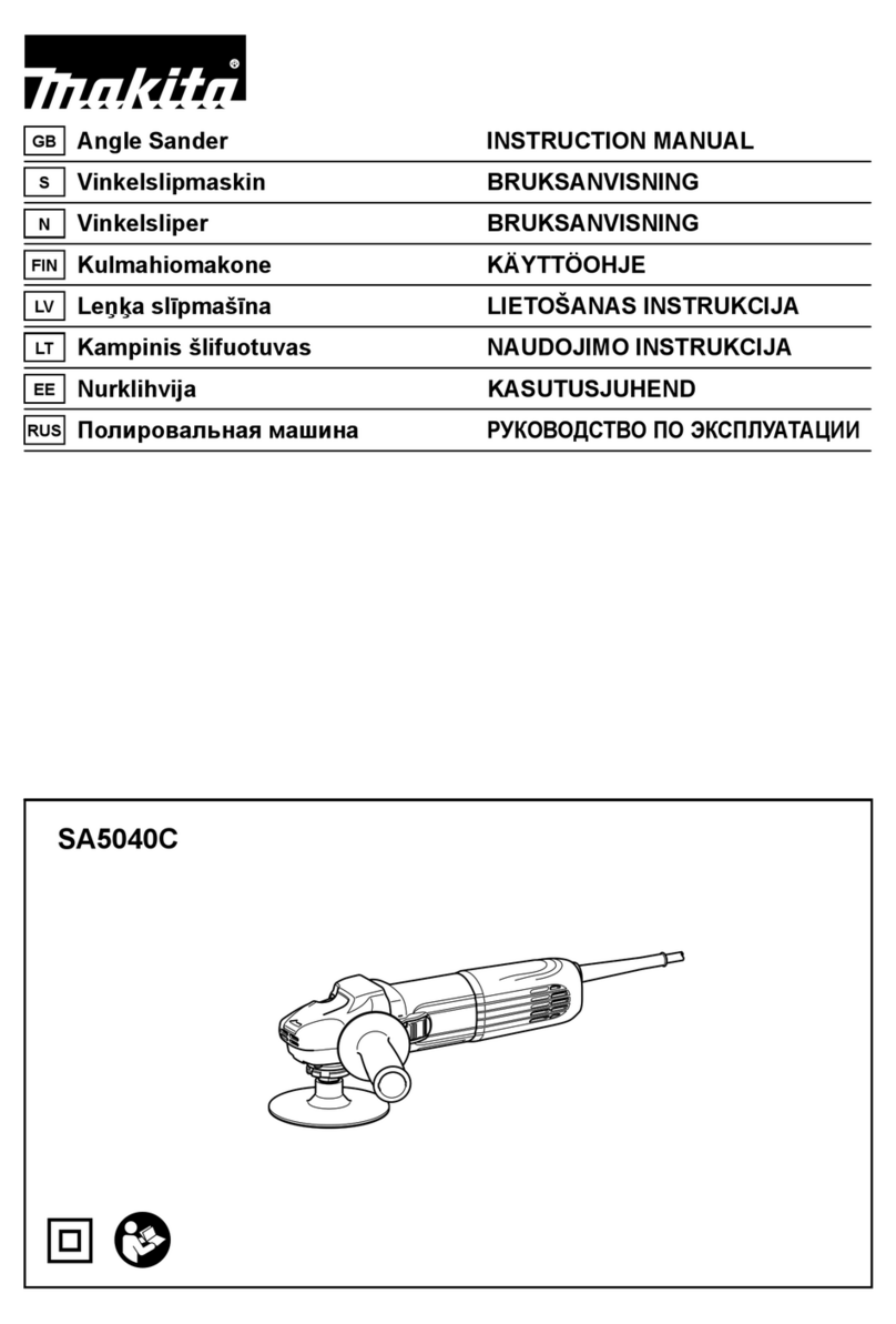
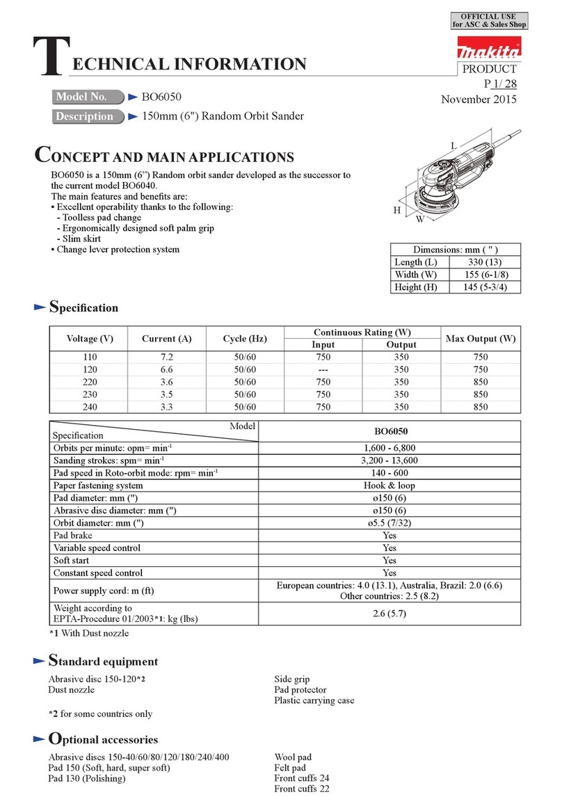
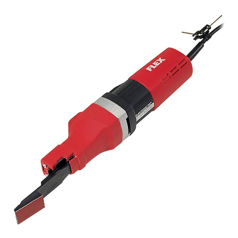
Makita GA7911 User manual

Sander
MODEL
GA7911
INSTRUCTION MANUAL
SPEC
IF
I
CAT
I
0
N
S
1
Overall length
1
Net weight
1
Spindle thread
No load speed
(RPMI
6,000
1
411.5
mm
(16-114”)
1
5.5
kg
(12.1
Ibs)
1
5/8-11
UNC
*
Manufacturer reserves the right to change specifications without notice.
Note: Specifications may differ from country to country.

I
M
PORTANT
SAFETY
INSTRUCTIONS
(For
All Tools)
WARNING:
WHEN USING ELECTRIC TOOLS, BASIC SAFE-
REDUCE THE RISK OF FIRE, ELECTRIC SHOCK, AND PER-
TY PRECAUTIONS SHOULD ALWAYS BE FOLLOWED TO
SONAL INJURY, INCLUDING THE FOLLOWING:
READ
ALL
INSTRUCTIONS.
1.
2.
3.
4.
5.
6.
7.
8.
9.
IO.
11.
12.
13.
2
KEEP WORK AREA CLEAN. Cluttered areas and benches invite injuries.
CONSIDER WORK AREA ENVIRONMENT. Don’t use power tools
in
damp
or wet locations. Keep work area well
lit.
Don‘t expose power tools to rain.
Don’t use tool in presence of flammable liquids or gases.
KEEP CHILDREN AWAY. All visitors should be kept away from work area.
Don’t let visitors contact tool or extension cord.
STORE IDLETOOLS. Whennot
in
use, toolsshould be stored indry, and high
or locked-upplace
-
out of reach of children.
DON’T FORCETOOL.
It
willdothejob betterandsafer at the ratefor which
it
was intended.
USE RIGHT TOOL. Don’t force small tool or attachment to do the job of a
heavy-duty tool. Don‘t use tool for purpose not intended.
DRESSPROPERLY. Don’t wear loose clothingorjewelry. They canbe caught
in
moving parts. Rubber gloves and non-skid footwear are recommended
when working outdoors. Wear protectivehair covering tocontain long hair.
USE SAFETY GLASSES. Also use face or dust mask if cutting operation is
dusty.
DON’T ABUSE CORD. Never carry tool by cord or yank
it
todisconnect from
receptacle. Keep cord from heat, oil, and sharp edges.
SECURE WORK. Use clamps or a vise to hold work. It‘s safer than using
your hand and
it
frees both hands to operate tool.
DON’T OVERREACH. Keep proper footing and balance at all times.
MAINTAINTOOLS WITH CARE. Keep tools sharp and clean for better and
safer performance. Follow instructionsfor lubricatingand changing acces-
sories. Inspecttoolcords periodicallyand
if
damaged, haverepairedby autho-
rized service facility. Inspect extension cords periodically and replace
if
damaged. Keep handles dry, clean, and free from oil and grease.
DISCONNECTTOOLS. When notinuse, before servicing, andwhen chang-
ing accessories, such as blades, bits, cutters.

14.
REMOVE ADJUSTING KEYS AND WRENCHES. Form habit of checking to
see that keysand adjusting wrenches are removed from
tool
before turning
it
on.
15.
AVOID UNINTENTIONALSTARTING. Don't carry plugged-intoolwithfinger
on switch. Be sure switch is OFF when plugging in.
16.
OUTDOOR USEEXTENSIONCORDS. Whentool is used outdoors, use only
extension cords intended for use outdoors and
so
marked.
17.
STAY ALERT. Watch what you are doing, usecommonsense. Don't operate
tool when you are tired.
18.
CHECK DAMAGEDPARTS. Before further use of the tool, a guard or other
part that is damaged should be carefully checked to determine that
it
will
operate properly and performitsintended function. Check for alignment of
movingparts, bindingof movingparts, breakageof parts, mounting, andany
other conditions that may affect its operation. A guard or other part that
is damaged should be properly repaired or replaced by an authorized serv-
ice center unless otherwise indicatedelsewhere
in
this instruction manual.
Have defective switches replaced by authorized service center. Don't use
tool if switch does not turn
it
on and off.
19.
GUARD AGAINST ELECTRIC SHOCK. Prevent body contact with grounded
surfaces. For example: pipes, radiators, ranges, refrigerator enclosures.
20.
PROPER GROUNDING. This toolshould be grounded while inuse toprotect
the operator from electric shock.
21.
EXTENSIONCORDS: Useonly three-wire extension cords which have three-
prong grounding-type plugs and three-pole receptacles which accept the
tool's plug. Replace or repair damaged or worn cord immediately.
VOLTAGE WARNING: Before connectingthe tool toa power source (receptacle,
outlet, etc.) be sure the voltage supplied is the same as that specified on the
nameplate of the tool. A power source with voltage greater than that specified
for the tool can result inSERIOUS INJURY to the user
-
as well as damage to
the tool. If
in
doubt, DO NOT PLUG IN THE TOOL. Using a power source with
voltage less than the nameplate rating is harmful to the motor.
3

GROUNDING INSTRUCTIONS
ALL GROUNDED, CORD-CONNECTEDTOOLS:
In
the event of a malfunction or
breakdown, grounding provides a path of least resistance for electric current to
reducethe risk of electric shock. This tool is equippedwithanelectric cord hav-
inganequipment-groundingconductor and a grounding plug. The plug mustbe
plugged intoamatchingoutlet that isproperly installedand grounded
in
accord-
ance with all local codes and ordinances.
Donot modifythe plugprovided-if
it
will
notfitthe outlet, havethe properout-
let installed by a qualified electrician.
Improper connection of the equipment.-groundingconductor can result ina risk
of electric shock. The conductor with insulation having an outer surface that is
green
with
or without yellow stripes is the equipment-grounding conductor. If
repair or replacement of the electric cord or plug is necessary, do not connect
the equipment-grounding conductor to a live terminal.
Check
with
aqualified electrician or servicemanifthe grounding instructions are
not completely understood, or if
in
doubt as to whether the tool is properly
grounded.
This tool is intended for use on a circuit that has an outlet that looks like the
one illustrated
in
FigureA. The toolhas a grounding plugthat looks like the plug
illustrated
in
FigureA.
A
temporary adapter, which looks like the adapter illus-
trated inFigure
B
and C, may be usedtoconnect this plugtoa 2-polereceptacle
as shown
in
Figure
B
if aproperlygroundedoutletisnotavailable. The temporary
adapter should be used only
until
a properlygrounded outlet can be installed
by
a
qualified electrician. The green-colored rigid ear, lug, etc. extending from the
adapter mustbeconnected toa permanent ground such asa properlygrounded
outlet box.
GROUNDING METHODS
FIG.
A
FIG.
0
FIG. C
L
Cover
of
Grounded
-
Outlet
Box
Grounding Pin
4
Grounding
Means

ADDITIONAL SAFETY RULES FOR SANDER
1.
Check the backing pad carefully for cracks, damage or deformity before
2,
Hold
the tool firmly.
3,
Keep hands away from rotating parts.
4.
Make sure abrasive disc is not contacting the workpiece before the switch
5,
Do not leave the tool running. Operate the tool only when hand-held.
6.
Donottouchthe workpiece immediatelyafteroperation;
it
may be extremely
operation. Replace cracked, damaged or deformed pad immediately.
is turned on.
hot and could burn your skin.
ADDITIONAL SAFETY RULES FOR GRINDER
1.
Keep guards in place.
2.
Useonly wheels havingamaximumoperating speedat least as highas
"No
Load RPM" marked
on
the tool's nameplate. When using depressed center
wheels, be sure to use only fiberglass-reinforced wheels.
3.
Check the wheel carefully for cracks or damage before operation. Replace
cracked or damaged wheel immediately.
4.
Use only flanges specified for this tool.
5.
Be careful not to damage the spindle, the flange (especially the installing
surface) or the lock nut. Damage to these parts could result in wheel
breakage.
6.
Hold the tool firmly.
7.
Keep hands away from rotating parts.
8.
Make sure the wheel is not contacting the workpiece before the switch is
turned on.
9.
Before using the tool on an actual workpiece, let
it
run for a while. Watch
for vibration or wobbling that could indicate poor installationor a poorly
balanced wheel.
IO.
Use the specified surface of the wheel to perform the grinding.
11.
Watch out for flying sparks. Holdthe tool
so
that sparks fly away from you
12.
Do not leave the tool running. Operate the tool only when hand-held.
13.
Donot touchthe workpiece immediately after operation;
it
maybeextremely
and other persons or flammable materials.
hot and could burn your skin.
SAVE THESE INSTRUCTIONS.
5

Installingside grip (auxiliaryhandle)
Screw the side grip on the tool securely.
The side grip can be installed on either side
of
the tool, whichever
is
convenient.
NOTE
:
Use sander accessoriesspecified in this manual. These must be purchasedby separate.
Installing or removingabrasivedisc
CAUTION
:
Always be sure that the tool
is
switched
off
and unpluggedbefore installingor removing
the disc.
Mount the rubber pad onto the spindle. Fit
the disc on over the rubber pad and screw
the lock nutonto the spindle.
Abrasive
disc
To
removethe disc, follow the installation procedure inreverse.
6

Switch action
To
start
the
tool, simply pull
the
trigger.
Release the trigger tostop. For continuous
operation, pull the trigger and then push in
the lock button.
To
stopthe tool fromthe
locked position, pull the trigger
fully,
then
release
it.
L-
Lock
button
CAUTION
:
Before plugging in the tool, always check to
see
that the trigger switch actuates properly
and returnstothe
"OFF"
positionwhen rele
Operation
Hold the tool firmly. Turnthe tool on and
then apply the abrasive disc to the work-
piece.
In general, keep
the
abrasive disc
at
an
angle of about
15"
to the workpiece sur-
face.
Apply slight pressure only. Excessive pres-
sure will result in poor performance and
prematurewear to the abrasive disc.
!ased.
7

IF
USED
AS
A
GRINDER
NOTE
:
Use grinder accessoriesspecified inthis manual. These must be purchased by separate.
WARN
I
NG
:
Always use guard assembly
or
accessory kit, noted below, for type 27 depressed center
wheel.
Guard assembly Guard accessory kit
Part No. 191214-3.
.
.
For 180mm (7")
Part No. 191215-1
. . .
For 230 mm
(9")
Part No. 191228-2.
.
.
For 180mm
(7")
Part No. 191231-3..
.
For 230 mm (9")
Installingor removingdepressedcenter wheel
CAUTION
:
Always be sure that the tool
is
switched off and unpluggedbeforeinstalling
or
removing
the wheel.
Mount the inner flange onto the spindle.
Fit the wheel on over the inner flange and
I
I
Depressed
center wheel
screw the lock nut onto the spindle.
I
Inner
flange
To tighten the lock nut, press the shaft
lock firmly
so
that the spindle cannot re-
volve, then use the lock nut wrench and
securely tighten clockwise.
To remove the wheel, follow the installationprocedurein reverse.
8

Operation
I
Hold
the
tool
firmly. Turn
the
tool
on
and
then apply the wheel or disc to the work-
piece.
In general, keep the edge of the wheel or
disc
at
an angle of about
15"
to the work-
piece surface.
During the break-in period with
a
new
wheel, do not work the grinder in the
B
direction or
it
will cut into the workpiece.
Once the edqe of the wheel has been
-
rounded
off
by use, the wheel may be
worked in both A and
B
directions.
I
WARN
I
NG
:
0
Itshould never be necessary to force the tool. The weight of the tool applies adequate
pressure. Forcingandexcessive pressurecouldcause dangerouswheel breakage.
0
Continued use of
a
worn-outwheel may result in wheel explosion and serious personal
injury. Depressed center wheel should not be used after
it
has been worn down to
11
5
mm
(4-1/2")
in
diameter. Use of the wheel after this point
is
unsafe and
it
should
be removedfromservice and rendered unusableby intentionaldestruction.
9

MAINTENANCE
CAUTION
:
Always be sure that the tool
is
switchedoff and unpluggedbefore attempting to perform
inspectionor maintenance.
Replacingcarbon brushes
Remove and check the carbon brushes
regularly. Replace when they wear down
to the limitmark. Keepthe carbon brushes
clean and free to slip in the holders. Both
carbon brushes should be replaced
at
the
same time. Use
only
Makitacarbonbrushes.
/
Limit
mark
Use
a
screwdriver to remove the brush
holder caps. Take out the worn carbon
brushes, insert the new ones and secure
the brush holdercaps.
To maintain product SAFETY and RELIABILITY, repairs, any other maintenance or
adjustment should be performed by Makita Authorized or Factory Service Centers,
always usingMakita replacementparts.
10

ACCESSORIES
CAUTION
:
These accessories or attachments are recommended for
use
with your Makita tool specified in this
manual. The
use
of
any other accessoriesor attachments might present
a
risk
of
injury
to
persons. The
accessories or attachments should
be
used only inthe proper and intended manner.
Part
No
191214 3
191215 1
@ Rubber pad
170
mm
(6-3/4“)
Part
No.
743012-7
Size
180
mm
(7”)
230
mm
(9”)
(3
Quick lock pad
Part No. 743012-5A
3
Abrasive discs
(IO
per pkg)
Diameter:
180
mm (7”)
(3
Quick lock paper
(IO
per pkg)
Diameter:
180
mm
(7“)
11

0
Inner flange
89
(fordepressed center wheel)
Part
No
224111
-9
24
741313-7A
@
(A) Depressed center wheel
(1pkg)
180
mm
x
6
mm
x
22
mm
17"
x
114"
x
7/8")
00
Part
No.
Part
No.
741413-3
741416-7
741421-4
741422-2 36
(7"
x
114"
x
7/8")
230
mm
x
6
mm
x
22
mm
(9"
x
114"
x
7/8'1
Grit
Size
(B)Makita zirconate
(5per pkg)
24
741413-6A
Part
NO
I
Grir
I
S,,r
180
mm
x
3mm
x
22
mm
(7"
x
1/8'
x
7/8")
191228-2
7"
@
Lock nut
45
(fordepressed center wheel)
Part
No.
224512-1
?~ITx?.~
@
Urethane washer
14
Part
No.
261039-0
7"
When using wire brush, mount urethane
washer 14to the spindle. Itwill make
it
easier to removewire brush.
0
Wire cup brush
191231-3
@
Flexible grinding wheel
(10 per pkg)
9"
Part
No.
I
Grit
I
Size
(mm)
794265-1
I
36
I
191231-3
180
x
3
x
22
(7"
x
118'
x
718")
(Includes
one
back
up
pad.@
794234-2
794235-0 Part
No
743027-41
I
9"
0
Lock nut wrench
28
Part
No.
782412-6
Grip
37
Part
No.
273480-5
0
Accessory kit
Includes:
Guard assembly, Inner flange,
Depressedcenter wheels,
Lock nut, Lock nut wrench.
12

Jan.-26-90
US
SANDER
Model
GA7911
Note: The switch and other part configurations
may differ from country to country.
13

MODEL
GA7911
':'OM
AfD
DESCRIPTION
MACHINE
__
1
2
3
4
6
7
6
9
10
11
12
13
14
15
16
17
18
19
20
21
22
23
24
25
1
1
1
4
1
1
1
1
1
1
1
1
1
1
1
1
1
1
1
1
2
1
2
1
Jan
-
26
-'90
US
'i\M
$fD
DESCRIPTION
Retaining
Ring
R-12
Pin
6
Pan
Head
Screw
M5x22 [With Washer1
Gear
Housing
0
Ring
36
Retaining
Ring
S-
11
Ring
11
Spiral
Bevel
Gear
17
Ball
Bearing
6301LLB
Plate
Woodruff Key 4
Fan 100
ARMATURE ASSEMBLY
(With
Item
14
-
171
Dust
Seal
10
Ball
Bearing
6200LB
FIELD ASSEMBLY
Handle
Set [With
Item
551
Rubber
Pin
4
Pan
Head
Screw
M4xB [With Washer1
Pan
Head
Screw
M5x65 (With Washer
&
Eondl
Motor
Housing
Insulation Washer
Retaininq Rinq
S
-
17
Compresslo" sprrng
7
MACHINE
~
26
27
28
29
30
31
32
33
34
35
42
43
44
45
47
48
49
50
51
52
53
54
55
LOO
-
1
1
1
1
1
1
1
1
1
4
1
2
2
2
1
1
2
2
4
3
1
1
1
1
-
Spiral
Bevel
Gear
56
Retaining
Ring
R-40
Ball
Bearing
6203LLB
0
Ring
40
Flat Washer 20
Felt
Ring
25
Spindle
Woodruff
Key
4
Bearing
Box
Pan
Head
Screw
M5x16 IWith Washer!
Name
Plate
Rivet
0-5
Carbon
Brush
Brush
Holder
Cap
Switch
Strain
Relief
Pan
Head
Screw
M4x10 IWith Washer1
Pan
Head
Screw
M4x18 IWith Warherl
Pan
Head
Screw
M5x22 [With Warherl
Pan
Head
Screw
M4x25 IWith Washerl
Cord
Cord
Guard
Handle
Set [With llem 191
Grip
37
Note The switch
and
other part specifications may
differ
from
country
to country
14

MAKITA
LIMITED
ONE
YEAR WARRANTY
Warranty Policy
Every Makita tool
IS
thoroughly inspected and tested before leaving the factory.
It
is
warranted to
be free of defects from workmanship and materials for the period of
ONE YEAR
from the date of
original purchase. Should any trouble develop during this one-year period, return the
COMPLETE
tool, freight prepaid, toone
of
Makita’s Factory or Authorized Service Centers. If inspection shows
the trouble is caused by defective workmanship or material, Makita will repair (or at our option,
replace) without charge.
This Warranty does not apply where:
repairs have been made or attempted by others:
repairs are required because of normal wear and tear:
The tool has been abused, misused or improperly maintained;
alterations have been made tothe tool.
IN NO EVENT SHALL MAKITA BE LIABLE FOR ANY INDIRECT, INCIDENTAL OR CON-
SEQUENTIAL DAMAGES FROM THE SALE OR USE
OF
THE PRODUCT. THIS DISCLAIMER
APPLIES BOTH DURING AND AFTER THE TERM
OF
THIS WARRANTY.
MAKITA DISCLAIMS LIABILITY FOR ANY IMPLIED WARRANTIES, INCLUDING IMPLIED
WARRANTIES OF “MERCHANTABILITY” AND “FITNESS FOR A SPECIFIC PURPOSE,”
AFTER THE ONE-YEAR TERM OF THIS WARRANTY.
This
Warranty gives you specific legal rights, and you may also have other rights which vary from
state to state. Some states do not allow the exclusion or Limitation of incidental or consequential
damages,
so
the above limitation or exclusion may not apply to you. Some states do not allow
limitation on how long an implied warranty lasts,
so
the above limitation may not apply toyou.
Makita Corporation
3-11
-8,
Sumiyoshi-cho,
Anjo, Aichi
446
Japan
883272D062 PRINTED INJAPAN
1991
-
6
-
N
Other manuals for GA7911
3
Table of contents
Other Makita Sander manuals

Makita
Makita BO4540 User manual

Makita
Makita 9207SPB User manual

Makita
Makita GV5010 User manual

Makita
Makita DBO180 User manual

Makita
Makita 9920 Quick start guide

Makita
Makita 9046J User manual

Makita
Makita 9046 User manual

Makita
Makita 9910 User manual

Makita
Makita BO4552 User manual

Makita
Makita 9901 User manual
Popular Sander manuals by other brands

Bosch
Bosch PSS 190 AC Original instructions

Porter-Cable
Porter-Cable 7800-XE instruction manual

Westfalia
Westfalia YT 2822 instruction manual

Clarke American Sanders
Clarke American Sanders 07057A Operator's manual

Universal Tool
Universal Tool UT8789-5-332CV Operating instructions, parts list & warranty

MIRKA
MIRKA ROS2-850CV manual