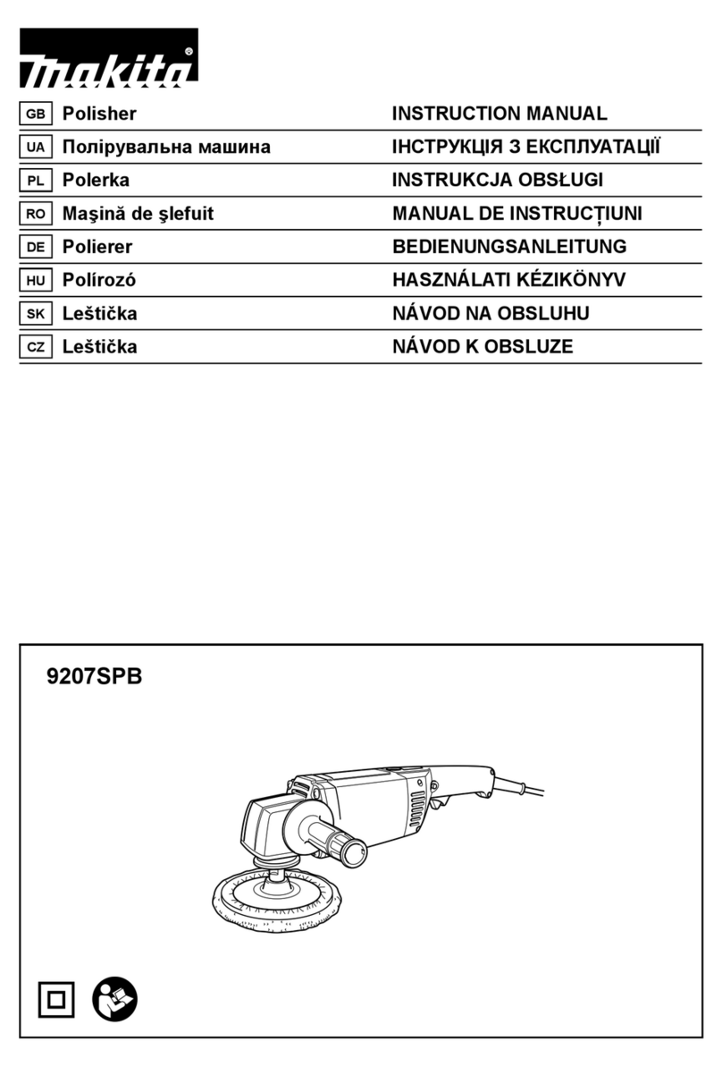
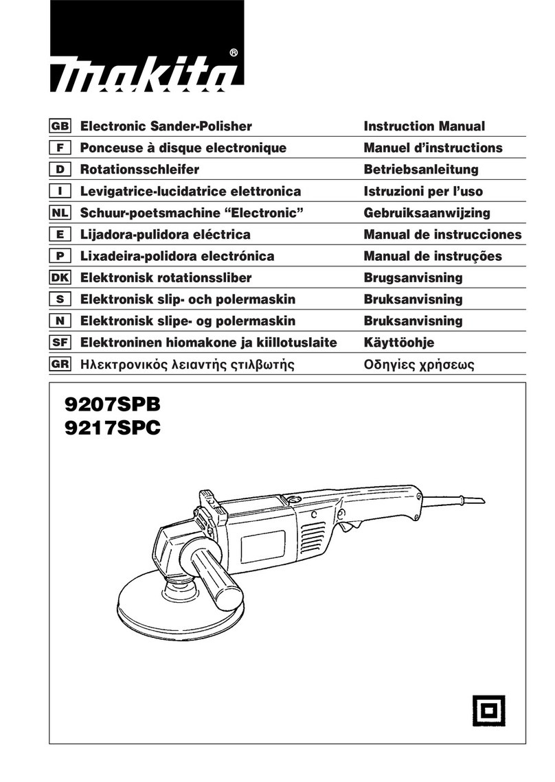
Makita SA7000C Manual

Continuous Rating (W)
Voltage (V) Cycle (Hz) Input Output Max. Output(W)
110 15
14
7.7
7.3
7.0
120
220
230
240
Models No.
Description
PRODUCT
Current (A)
TECHNICAL INFORMATION
CONCEPT AND MAIN APPLICATIONS
Specification
Standard equipment
Optional accessories
P 1 / 6
Dimensions: mm (")
Width (W)
Height (H)
Length (L)
50 / 60
50 / 60
50 / 60
50 / 60
50 / 60
1,600
1,600
1,600
1,600
1,600
700
700
700
700
700
2,700
2,700
2,700
2,500
2,500
170 (6-11/16)
453 (17-7/8)
136 (5-3/8)
W
L
0 - 1,500/4,000
Electronic features
No load speed: min.-1 = rpm.
Abrasive disc
Pad
Speed adjusting dial
Soft start
Constant speed
Capacity: mm (")
Cord length: m (ft)
Net weight: kg (lbs)
180 (7)
2.5 (8.2)
3.2 (7.1)
2.0 (6.5)
180 (7)
Yes
Current limiter Yes
Yes
Yes
Australia
Others
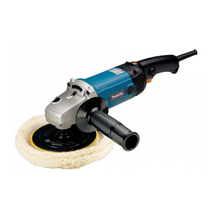
Model SA7000C is a new electronic angle sander developed
as a series model of GA7010C/GA9010C.
And its advantages are;
*Powerful with 1600W motor
*Yet still has high heat-resistance even in sanding at the
lowest speed.
*Electronic with soft start, current limiter and constant speed
under load
SA7000C
Angle Sander 180mm (7")
*Lock nut wrench 35 ..................................... 1
*Sanding lock nut 14-18 ............................... 1
*Rubber pad 170 ............................................ 1
*Head cover ................................................... 1
*(+) Round head screw M14 ......................... 2
Note: The standard equipment for the tool shown may differ from country to country.
*Assorted accessories for 180mm (7") angle sander
H

Repair
P 2 / 6
Put 40g of Makita grease SG. No.0 into the gear room of Gear housing
for a long gear life. (Fig. 1)
[2] Lubrication
1R291/ Retaining Ring S and R Pliers Removal/Installation of the Retaining ring that retains larger Spiral bevel gear
1R340/ Bearing Retainer Wrench Removal/Installation of Bearing retainer
1R229/ 1/4" Hex Shank Bit M5 Removal/Installation of the Hex socket head bolts that fasten Bearing box
1R269/ Bearing Extractor Removing ball bearing 608DDW on the commutator end of Armature shaft
1R045/ Gear Extractor (large) Removing Gear housing cover and Bearing box
1R035/ Bearing Setting Plate Press-fitting Ball bearings
Tool No./ Description Use for
[1] Necessary Repairing Tools
[3]-1. Replacing Armature and Ball Bearing 6201LLB
[3] Disassembling and Assembling
1) After removing Carbon brushes, Remove Grip 36 complete.
Separate Head cover from Gear housing by removing two M14x10
(+) Round head screws with Phillips screwdriver No.3 or the like.
2) Separate Gear housing section from Motor housing by removing
four 5x30 Tapping screws.
3) Slide Gear housing cover until you see the corners on the end of
Motor housing. And then by striking two of the corners with plastic
hammer, the assembly of Armature and Gear housing cover can be
separated from Motor housing. (Fig. 2)
4) Remove Hex nut M6 by turning counterclockwise while holding
Armature firmly by hand. Now smaller Spiral bevel gear can be
removed from Armature shaft by hand.
4) Remove Gear housing cover from Armature using Gear Extractor,
large (No.1R045). (Fig. 3) Ball bearing 6201LLB is still on Gear
housing cover at this step. Therefore, remove the bearing with
arbor press and a round bar. (Fig. 4)
Note: Disassembling can be done without disassembling Gear
housing section.
CAUTION: For your safety, before maintenance or repair, be sure to;
1. Disconnect the machine from the power source.
2. Remove the wheel from the machine.
Gear room
Fig. 1
Fig. 2
Fig. 3 Fig. 4
DISASSEMBLING
Ball bearing 6201LLB Ball bearing 6201LLB
Gear housing cover
Gear housing cover
Gear Extractor, large (No.1R045) Round bar
Slide Gear
housing cover.
Strike two corners
on the end of
Motor housing.
Repair
P 3 / 6
[2]- 2. Replacing Spiral Bevel Gear 43 and Ball Bearing 6202DDW
1) Insert ball bearing 6201LLB straight into Gear housing cover.
And then put Bearing setting plate (No.1R035) on arbor press, and then put Gear housing cover on Bearing setting plate.
Press-fit Armature to Gear housing cover using arbor press. (Fig. 5)
2) Install smaller Spiral bevel gear on Armature shaft, and tighten Hex nut M6 securely with a spanner 10.
And then install the assembly of Armature and Gear housing cover on motor housing, and align the screw holes on Gear
housing cover with those of Motor housing.

3) Aligning the protrusion on gear housing with that on Motor housing, fit Gear housing to gear housing cover. (Fig. 6)
Fasten Gear housing to Gear housing cover and Motor housing with four 5x30 Tapping screws.
4) Install Head cover and Grip 36 complete.
1) Remove Sanding pad.
2) Using a Makita impact driver and Hex shank bit M5 (No. 1R229), remove four M5x16 Hex socket bolts that fasten
Bearing box to Gear housing.
3) Insert two slotted screwdrivers into two diagonal positions on the slit between Bearing box and Gear housing.
And twist the two screwdrivers at the same time till Bearing box is lifted up approximately 3mm.
And then insert the screwdrivers further into the slit, and remove Gear housing from Gear housing cover by lifting it
up with the screwdrivers. (Fig. 7)
Follow the reverse of disassembling procedure as described below.
Fig. 5 Fig. 6
Fig. 7
ASSEMBLING
DISASSEMBLING
Bearing Setting Plate
(No.1R035)
Gear housing cover
Armature
Gear housing Gear housing cover
Motor housing
Align the projection on Gear housing
with that on Motor housing.
Slotted screwdriver
Bearing box
Gear hosing
Note: Disassembling can be done without disassembling Gear housing section.
(continued to next page)

Repair
P 4 / 6
[3]- 2. Replacing Spiral Bevel Gear 43 and Ball Bearing 6202DDW (cont.)
[3]- 3. Replacing Shaft Lock Section
3) Remove Ball bearing 608LLB from spindle using Bearing extractor (No.1R269) as illustrated to left in Fig. 8.
4) Remove Retaining ring S-15 from Spindle using Retaining ring S and R pliers (No.1R291) as illustrated
to right in Fig. 8. Now Spiral bevel gear 43 and Woodruff key can be removed from Spindle by hand.
5) Remove spindle by pushing with Gear Extractor, large (No.1R045). (Fig. 9)
6) Hold Bearing box securely with vise, and remove
Bearing retainer from Bearing box using Bearing
retainer wrench (No.1R340) as illustrated in Fig. 10.
7) Remove Ball bearing 6202DDW from Bearing box
by hitting it straight against the surface of work bench.
If cannot be removed, use arbor press.
Fig. 8 Fig. 9
Fig. 10
Fig. 11
Fig. 12
DISASSEMBLING
Follow the reverse of disassembling steps.
Note: When installing Spiral bevel gear 43 onto Spindle,
Be careful not to allow Woodruff key 4 to be out of position.
It is recommended to apply grease to the key slot on Spindle
in order to hold the Woodruff key securely in place. (Fig. 11)
1) Remove Bearing box from Gear housing. (Fig. 7)
2) Pull off Shoulder pin 7 with pliers while pushing Pin cap with a
finger. (Fig. 12)
Note: Do not pull off shoulder pin 7 without holding pin cap because
Compression spring 7 would sling Pin cap.
Follow the reverse of disassembling steps.
Note: Do not reinstall removed Pin cap because removal of Shoulder
pin 7 damages the inside surface of Pin cap. Be sure to remove
plastic dust of Pin cap from Shoulder pin 7 and to install it onto
a brand-new Pin cap.
ASSEMBLING
DISASSEMBLING
ASSEMBLING
Ball bearing
608LLB
Bearing Extractor
(No.1R269) Retaining Ring
S and R Pliers
(No.1R291)
Retaining
ring S-15
Bearing box
Spindle
Gear Extractor, large (No.1R045)
Bearing box
Turn the handle of
Bearing retainer
wrench (No.1R340)
counterclockwise.
Woodruff key 4
Spiral bevel gear 43
Pin cap
Gear housing
Shoulder pin 7
Compression
spring 7

Circuit diagram
Wiring diagram
P 5 / 6
Color index of lead wires' sheath
Black
White
Red
Orange
Blue
Power supply cord
Controller
Switch
Field
Pick up coil
Noise
suppressor
Insulated
connector
Insulated
terminal
Insulated
connector
[1] Wiring on Motor Housing
Choke coil
Insulated
connector
Blue or white
The parts illustrated in this
gray square are not used
for some countries.
1) Draw the lead wires of (a), (b), (c), (d), (e) and (f) through
the openings (areas colored gray), and hold them with lead wire holders. (Fig. 14)
2) And then route the lead wires as illustrated below in Fig. 14.
Note: Illustrated in Fig. 14 is Motor housing viewed from the side of A.
Fig. 13
Fig. 14
Pickup coil
(d) Connecting lead wire (black)
of brush holder
(e) Connecting lead wire (black)
of brush holder
(b) Field lead wires (black)
Put (f) Field lead wire (black) on the
lead wire from Choke coil (orange)*
when holding them with lead wire
holder.
Put insulated connector
in this compartment
on Motor housing.
Put insulated connector
in this compartment
on Motor housing.
(c) Field lead wire
(black)
(a) Field lead wire
(white)
Lead wire from
Choke coil (orange)*
Lead wire from Choke coil (orange)*
Choke coil*
Put choke coil* into
this opening.
(f) Field lead wire (black)
[A]
Motor housing
*Some countries do not use Choke coil.
Lead wire
holders
Connector
Speed adjust dial
Heat shrink tube
[Pickup coil side]

Wiring diagram
P 6 / 6
Fig. 15
Fig. 17
[2] Wiring of the Lead Wires of Pickup Coil
[3] Wiring in Handle
Lead wire of
pickup coil
(white)
Lead wire of
pickup coil
(black)
Rib
Lead wire holder
1) First, route the white lead wire of pickup coil under the rib.
And then hold both of the white and the black lead wires
with the lead wire holder. (Fig. 15)
2) When installing Handle (L) onto Motor housing, route the
two lead wires as illustrated in Fig. 16.
Boss on Handle (L)
Handle (L)
Rib
a) Lead wire from Controller (blue or white)
c) Lead wire from Controller (red)
d) Lead wire from Choke coil (red)*
Note: The position of band that of dare replaceable.
b) Field lead wire (white)
Switch
Noise suppressor*
Before setting Switch in place, hold the three (or four) lead wires with the lead wire holders under switch as
illustrated below. When using Choke coil, place the lead wire dunder other lead wire as illustrated below.
Lead wire holders
Fig. 16
Route the lead wires
that connect Controller
with Speed adjust dial
between these ribs, and
put them under the dial.
Rib Boss
Note: Some countries do not use the electrical parts with an asterisk.
Pickup coil
Motor housing
Pickup coil
Lead wire
holder A
Lead wire
holder B
Lead wire holder C
Speed adjust dial
Controller
Route lead wires between rib and boss
and between rib and wall of handle (L).
With Lead wire holder C, hold more
than one lead wire that is connected
with this insulated terminal.
Insulated connector*
Insulated connector
(Use for connecting the
lead wire from Choke
coil with the lead wire
from Noise suppressor.)
With Lead wire holder A, hold the lead wires that connect
Controller with Connector on Switch.
With Lead wire holder B, hold the other lead wires.
At this time, put the lead wire from Controller (blue or white)
and the lead wire from Choke coil (orange)* under the other
lead wires.
Other manuals for SA7000C
10
Table of contents
Other Makita Sander manuals

Makita
Makita BO4555 User manual

Makita
Makita 9046 User manual

Makita
Makita BO6030 User manual

Makita
Makita BO4566J User manual

Makita
Makita DBO380 User manual

Makita
Makita 9237CB User manual

Makita
Makita 9920 Quick start guide

Makita
Makita BO3710 User manual

Makita
Makita SA9031 User manual

Makita
Makita PV001GZX05 User manual

Makita
Makita 9046 User manual

Makita
Makita BO4555 User manual

Makita
Makita BBO140 User manual

Makita
Makita BO4556 User manual

Makita
Makita BO4900V Quick start guide

Makita
Makita BO4510 User manual

Makita
Makita BO5020 User manual

Makita
Makita DSL800 User manual

Makita
Makita BO5030 User manual

Makita
Makita BBO140 User manual