Makita 5402NA User manual

a
Blade
diameter
Circular
Saw
weight
Max. cutting capacities
No
load speed Overall
(RPMl
1
length
at
900
I
at
45O
415
mm
(16-5/16”)
MODEL
5402NA
Equipped
with
Electric Blade
Brake
616
mm
2,2001min. (24-114”)
415
mm
158
mm
106
mm
(1
6-5/16”)
(6-3/16”) (4-3/16“)
INSTRUCTION MANUAL
13.0
Kg
(28.71bs)
SPECIFICATIONS
Manufacturer reserves the right to change specifications without notice.
*Note:
Specifications
may
differ from country to country.
WARNING: For your personal safety, READ and UNDERSTAND before using.
SAVE THESE INSTRUCTIONS FOR FUTURE REFERENCE.

GENERAL
SAFETY
RULES
(For
All Tools)
WARNING! Read and understand
all
instructions. Failure
to
follow
all instructions listed
below,
may result
in
electric
shock, fire andlor serious personal injury.
SAVE THESE INSTRUCTIONS
Work Area
1.
Keepyour work areacleanandwell
lit.
Cluttered benchesand dark areas invite
accidents.
2.
Do
notoperate powertools
in
explosiveatmospheres, suchas inthe presence
of flammable liquids, gases, or dust. Power tools create sparks which may
ignite the dust or fumes.
3.
Keep bystanders, children, and visitors away while operating a power tool.
Distractions can cause you to lose control.
Electrical Safety
4.
Grounded tools must be plugged into an outlet properly installed and
grounded
in
accordance with all codes and ordinances. Never remove the
groundingprongor modifythe
plug
in
any way.
Do
notuse any adaptorplugs.
Check withaqualifiedelectrician
if
you are indoubtasto whether the outlet
is properlygrounded.
If
the tools should electrically malfunction or breakdown,
grounding provides a low resistance path to carry electricity away from the
user.
5.
Avoid body contact withgroundedsurfaces suchas pipes, radiators, ranges
and refrigerators. There is an increased risk of electric shock if
your
body is
grounded.
6.
Do
notexpose power tools torainor wet conditions. Water entering a power
tool
will
increase the risk of electric shock.
7.
Do
notabuse the cord. Never usethe cordtocarrythe tools or
pull
the plug
from anoutlet. Keepcord awayfrom heat, oil, sharpedges or movingparts.
Replace damaged cords immediately. Damaged cords increase the risk of
electric shock.
8.
Whenoperating apowertooloutside, useanoutdoor extension cordmarked
“W-A’
or “W.” These cords are rated for outdoor use and reduce the risk
of electric shock.
Personal Safety
9.
Stay alert, watchwhat youare doingandusecommon sense whenoperating
a power tool.
Do
not use tool while tired or under the influence of drugs,
alcohol, or medication.
A
momentof inattention while operating powertools
may result
in
serious personal injury.
2

IO.
Dressproperly.
Do
notwear loose clothingorjewelry. Contain long hair. Keep
your hair, clothing, andgloves away frommovingparts. Looseclothes, jewelry
or long hair can be caught
in
moving parts.
11.
Avoid accidental starting. Be sure switch is off before plugging
in.
Carrying
tools withyour finger on the switch or plugging intools that havethe switch
on invites accidents.
12. Remove adjusting keys or wrenches before turning the tool on. A wrench
or a key that is left attached to a rotating part of the tool may result
in
per-
sonal injury.
13.
Do
notoverreach. Keep properfootingandbalanceatalltimes. Proper footing
and balance enables better control of the tool in unexpected situations.
14. Use safety equipment. Always wear eye protection. Dust mask, non-skid
safety shoes, hard hat, or hearing protection must be used for appropriate
conditions.
Tool
Use and Care
15. Use clamps or other practical way to secure and support the workpiece to
a stable platform. Holdingthe work by hand or against your body is unstable
and may lead to
loss
of control.
16.
Do notforce tool. Usethe correcttoolfor your application. The correct tool
will
do the job better and safer at
the
rate for which
it
is designed.
17.
Do
not use tool if switch does not turn
it
on or off. Any tool that cannot
be controlled with the switch is dangerous and must be repaired.
18.
Disconnectthe plug from the power source before makingany adjustments,
changing accessories, or storing the tool. Such preventive safety measures
reduce the risk of starting the tool accidentally.
19.
Store idle tools out of reach of children and other untrained persons. Tools
are dangerous in the hands of untrained users.
20. Maintain tools with care. Keep cutting tools sharp and clean. Properly
maintained tools,
with
sharp cuttingedgesare lesslikely to bind and are easier
to control.
21. Check for misalignment or binding of moving parts, breakage of parts, and
any other condition that may affect the tools operation.
If
damaged, have
the tool serviced before using. Many accidents are caused by poorly main-
tained tools.
22. Use only accessories that are recommended
by
the manufacturer for your
model. Accessories that may be suitable for one tool, may become hazardous
when used on another tool.
Service
23.
Tool
service must be performedonly by qualified repair personnel. Service
or
maintenance performed by unqualified personnel could result in a risk of
injury.
24.
When servicing atool, useonly identical replacementparts.
Follow
instruc-
tions inthe Maintenance section of this manual. Use of unauthorized parts
or failuretofollow Maintenance Instructions maycreatea risk of electric shock
or injury.
3

US0044-1
Specific Safety
Rules
1.
DANGER! Keep handsaway from cutting area andblade. Keep your second
handonauxiliary handleor motorhousing. If bothhandsare holdingthe saw,
they cannot be cut by the blade.
Keep your body positionedto either side of the saw blade, but not
in
line
withthe
saw
blade. KICKBACKcouldcausethe saw tojump backwards. (See
"Causes and Operator Prevention of Kickback")
Do
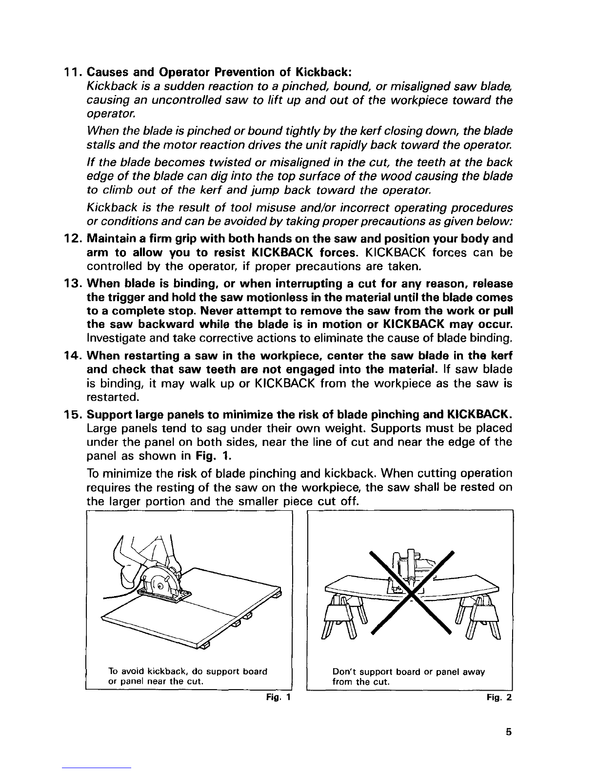
not reach underneaththe work. The guard can not protect you from the
blade below the work. Don't attempt to remove cut material when blade is
moving.
CAUTION: Blades coast after turn off.
2.
Check lower guard for proper closing before each use.
Do
not operate saw
if
lower guard does not move freely and close instantly. Never clamp or tie
the lower guardintothe open position. If saw isaccidentally dropped, lower
guard may be bent. Raisethe lowerguardwiththe RetractingHandleandmake
sure
it
movesfreely and does nottouch the bladeor any other part, inall angles
and depths of cut.
3.
Check the operation and condition of the lower guard spring.
If
the guard
andthe spring are notoperating properly, they mustbeserviced before use.
Lower guard may operate sluggishly due todamaged parts, gummy deposits,
or
a
buildup of debris.
4.
Lower guard should be retracted manually only for special cuts such as
"Pocket Cuts" and "Compound Cuts." Raise lower guard
by
Retracting
Handle.As soonas blade enters the material, lower guardmust bereleased.
For
all
other sawing, the lower guard should operate automatically.
5.
Always observe that the lower guard is covering the blade before placing
saw down on bench or floor. An unprotected, coasting blade will cause the
saw towalk backwards, cutting whatever is
in
its path. Be aware of the time
it
takes for the blade to stop after switch is released.
6.
NEVER
holdpiece being cut
in
your handsor acrossyour leg.
It
is important
to support the work properly to minimize body exposure, blade binding, or
loss
of control.
7.
Holdtoolby insulatedgrippingsurfaces when performing
an
operationwhere
the cutting tool may contact hidden wiring or its own cord. Contact with
a
"live" wire will also makeexposed metal parts of the tool "live" and shock
the operator.
8.
When ripping always use a
rip
fence or straight edge guide. This improves
the accuracy of cut and reduces the chance for blade binding.
9.
Always use blades with correct size and shape (diamond vs. round) arbor
holes. Blades that do not matchthe mounting hardware
of
the saw will run
eccentrically, causing
loss
of control.
IO.
Never use damagedor incorrect blade washers or bolts. The blade washers
and bolt were specially designed for your saw, for optimum performance and
safety of operation.
4

11.
Causes and Operator Prevention of Kickback:
Kickback is a suddenreaction toa pinched, bound, or misalignedsaw blade,
causing an uncontrolled saw to lift up and out of the workpiece toward the
operator.
Whenthe bladeis pinched or bound tightly by thekerf closingdown, theblade
stalls and themotor reaction drives theunitrapidly back toward the operator.
If the blade becomes twisted or misaligned in the cut, the teeth at the back
edge of theblade can dig into the topsurface of the wood causing the blade
to climb out of the kerf and jump back toward the operator.
Kickback
is
the result
of
tool misuse and/or incorrect operating procedures
or conditions and canbe avoidedby takingproperprecautionsas givenbelow:
12.
Maintaina firmgrip withbothhands onthesaw and position your body and
arm to allow you to resist KICKBACK forces. KICKBACK forces can be
controlled
by
the operator,
if
proper precautions are taken.
13.
When blade is binding, or when interrupting a cut for any reason, release
thetrigger and holdthesaw motionless
in
thematerial
until
the bladecomes
toa complete stop. Never attempt to remove the saw from the work or pull
the saw backward while the blade is
in
motion or KICKBACK may occur.
Investigate andtake corrective actionstoeliminate the cause of blade
binding.
14.
When restarting a saw
in
the workpiece, center the saw blade
in
the kerf
and check that saw teeth are not engaged into the material.
If
saw blade
is
binding,
it
may walk
up
or KICKBACK from the workpiece as the saw is
restarted.
15.
Support large panelsto minimize the risk of blade pinching and KICKBACK.
Large panels tend tosag under their own weight. Supports must be placed
under the panel on bothsides, near the line of cut and near the edge of the
panel as shown
in
Fig.
1.
To
minimize the risk of blade pinchingand kickback. When cutting operation
requires the resting of the saw onthe workpiece, the saw shall be rested on
the larger portion and the smaller piece cut off.
To
avoid kickback, do support board
or panel near the cut. Don't support board or panel away
from
the
cut.
Fig.
1
Fig.
2
5

16.
Do
not use dull or damaged blade. Unsharpened or improperly set blades
produce narrow kerf causingexcessivefriction, bladebindingand KICKBACK.
17. Bladedepthandbeveladjustinglocking leversmustbetight andsecurebefore
makingcut.
If
bladeadjustment shifts while cutting,
it
will cause bindingand
KICKBACK
.
18.
Useextra caution when makinga "Pocket Cut" intoexisting walls or other
blindareas. The protruding blademay cut objects that can cause KICKBACK.
NEVER
place your hand or fingers
behind the saw. If kickback occurs,
the saw couldeasilyjump backwards
over your hand, possibly causing
severe injury.
Fig.
:
19. Adjustments. Before cutting be
sure
depth and beveladjustments are tight.
20. Avoid Cutting Nails. Inspect for and remove all nails from lumber before
cutting.
21.
When operating the saw, keep the
cord away from the cuttingarea and
position
it
so
that
it
willnotbecaught
on
the
workpiece during the cutting
operation.
Operate with proper hand support,
proper workpiece support, and sup-
ply cord routingaway from the work
area.
Fig.
4
WARN
IN
G
:
It
is important tosupport the workpiece properly andtoholdthe saw firmly
to prevent
loss
of controlwhich couldcause personalinjury. Fig.
4
illustrates
typical hand support of the saw.
22. Placethe wider portionof the saw base onthat part of the workpiece which
issolidlysupported, notonthe section that willfall off when the cutismade.
As examples, Fig.
5
illustrates the RIGHTway tocut off the end of
a
board,
andFig.
6
the
WRONG
way.
If
the workpieceisshort or small, clamp
it
down.
DON'T TRY TO
HOLD SHORT PLACES
BY
HAND!
6

Fig.
C
23.
Never attempt to saw with the
circular saw held upside down in a
vise. This is extremelydangerousand
can lead to serious accidents.
Fig.
I
I
Fig.
24.
Before setting the
tool
down after completing
a
cut, be sure that the lower
(telescoping)guard has closed and the blade has come to a complete stop.
SAVE THESE INSTRUCTIONS.
SYMBOLS
Thefollowings show the symbols usedfor tool.
v
....................................
volts
A
....................................
amperes
Hz
....................................
herts
'L
....................................
alternatingcurrent
....................................
no loadspeed
..Jmin
...................................
revolutions
or
reciprocationper minute
7

FUNCTIONALDESCRIPTION
CAUTION:
Always be sure that the tool is switched off and unplugged before any adjustment is
attempted.
Adjustingdepth
of
cut
Loosen the lever on the depth guide and
movethe baseupor down.
At the desired depth of cut, secure the
baseby tighteningthe lever.
Lever
1
I
CAUTION
Fig.
Use
a
shallowdepth of cut when cuttingthin workpiece for cleaner, safer cuts.
*After adjustingthe depth of cut, always tighten the leversecurely.
Bevel
cutting
Loosen the lever on the bevel scale plate
on the front of the base and the clamp
screwon the back.
Set for the desiredangle
(0
-
45")
by tilting
accordingly, then tighten the lever and the
clampscrew securely.
/
Clamp
screw
Lever
Bevelscale
plate
I
Fig.
!
8

Adjustingfor accuracy
of
90"
cut (verticalcut)
This adjustment has been madeat the factory. But
if
it
is off, adjust the adjustingscrew
with the hex wrench while squaring the blade with the base using
a
triangular rule or
try
square, etc.
Sighting
For straight cuts, align the right notch on
the front
of
the basewithyour cutting line
on the workpiece.
For
45"
bevel
cuts,
align
the
left notchwith
it.
i
rBase
Adjustingscrew
For straight
cuts
Baseplate
Fig.
'IC
CAUTION
Fig.
1
After adjustingthe depth of cut and bevelcuttingangle, be sure to tighten the screw.
Bladesteady device
In general way, use the lock lever by set-
ting
it
in lockedposition.
To lock the lock lever, push it down and
turn
it
90"
counterclockwise.To releasethe
lock lever, turn
it
90"
clockwise. When you
replace
a
saw blade, releasethe lock lever.
Release
Lock
9

Switchaction
CAUTION:
Beforepluggingintothe tool, always check tosee that the switch triggeractuates properly
and returnsto the
"OFF"
positionwhen released.
To prevent the switch trigger from being
accidentally pulled,
a
lock-off button
is
pro-
vided.
To
start the tool, depressthe lock-off
buttonand pullthe switch trigger.
Releasethe switch trigger to stop.
Lock-oft
button
Fig.
14
ASSEMBLY
Removing
or
installingsaw
blade
CAUTION:
Always be surethat the tool is switched
off
and unpluggedbefore removing
of
installing
the blade.
Release the lock lever of blade steady
device.
To remove the blade, press the shaft lock
so
that the blade cannot revolve and use
the hex wrench to loosen the hex bolt
counterclockwise. Then remove the hex
socketheadbolt, outer flange and blade.
To installthe blade, follow the removalpro-
cedurein reverse.
BE SURE
TO
TIGHTEN THE HEX SOCKET
HEAD
BOLTSECURELY.
After installing the blade, lock the lock
lever.
Hex
lock
I
Fig.
l!
Outer
flange
I
Fig.
1(
10

CAUTION:
Be sure the blade is installedwith teeth pointingup
at
the front of the tool.
Useonly the Makitahex wrench to installor removethe blade.
*The inner flange has
a
25 mm(63/64")diameteron one sideand
a
25.4mm
(1")
diameter
on the other. The side with 25.4mm
(I")
diameteris markedby "25.4".
Usethe correct side for the hole diameter
of
the blade you intendto use. Mountingthe
bladeon the wrong side can result in dangerousvibration.
J
shaft
);:e
25.4
mm
marking
t
-_
Ring
Fig.
1'
Hex
wrench
storage
The hex wrench can be convenientlystored
inthe lever.
Hex
wrench
5
,\
-
Fig.
1i
To remove the hex wrench, push the
I
shorter side of itout withyour finger.
Then removethe hex wrench.
Push
-1
,
Fig.
l!
11

To
store the hexwrench, insert the lonaer
I
side of
it
into the lever.
Thenwshthe shorterside of
it
down.
OPERATION
Grasp the rear handlewith your right hand,
the front grip with your left. Set the base
plate on the workpiece to be cut without
the blade making any contact. Then turn
the tool on and wait until the blade attains
full speed. Now simply move the tool for-
ward over the workpiece surface, keeping
it
flat and advancing smoothly until the
sawing is completed. To get clean cuts,
keep your sawing line straight and
your
speed advanceuniform.
0
Push
Insert
Fig.
2(
I
Fig.
2'
CAUTION:
Grasp the rear handle and the front grip firmly when starting or stopping the tool, since
there isan initialand final reaction.
Rip
fence (guiderule)
The handy ripfence (guide rule)allowsyou
to do extra-accurate straight cuts. Simply
slide the rip fence up snugly against the
side of the workpiece and secure
it
inposi-
tion with the clamp screw on the front of
the base.
It
also makes repeated cuts
of
uniformwidth possible.
Guide
rule
Fig.
2
12

MAINTENANCE
CAUTION:
Always be sure that the tool is switched
off
and unpluggedbefore attempting to perform
inspectionor maintenance.
Replacingcarbonbrushes
Removeandcheck the carbon brushes reg-
ularly. Replace when they wear down to
the limit mark. Keep the carbon brushes
clean and free to slip in the holders. Both
carbon brushes should be replaced
at
the
same time. Use only identical carbon
brushes.
Use
a
screwdriver to remove the brush
holder caps. Take out the worn carbon
brushes, insert the new ones and secure
the brushholder caps.
Limit
mark
I’
Fig.
2
I
I
Fig.
2
To maintainproductSAFETY and RELIABILITY,repairs, maintenanceor adjustment should
be performed by Makita Authorized or Factory Service Centers, always using Makita
replacementparts.
13

ACCESSORIES
CAUTION:
These accessories or attachments are recommended for use with your Makita tool specified in this
manual. The use of any other accessories or attachments might present a risk
of
injun/ to persons.
The accessoriesor attachments should be used only inthe proper and intended manner.
Part
No,
Tungsten carbide-tipped saw blade
For wood Diameter Hole diameter
No.
(mm) teeth
A-90956
415
I
721704-8
I
(16-5/16")
I
(6f64")
I
6o
32
415 25
(16-5/16") (63/64")
Part
No,
For rip and cross cut work Diameter Holediameter
No.
(mm)
("1
teeth
Cross cut saw blade
For smoother cross-graincuts
Rip saw blade
For faster cuttingwith grain.
Guide rule
Part
No.164019-4
Hex wrench
Part
No.
783203-8
I
t,",9;,
I
I
Part
No,
I
DiFan$r
I
Holediameter
(mm)
I
I
I
I
14

WARNING
Some dust created by power sanding, sawing, grinding, drilling, and other
construction activitiescontains chemicals known
[to
the State
of
California]
to
cause cancer, birth defects or other reproductive harm. Some examples
of
these chemicals are:
0
Leadfrom lead-based paints,
Crystalline silicafrom bricksand cement and other masonry products, and
Arsenic andchromium from chemically-treated lumber.
Your risk from these exposures varies, depending on how often you do this
type
of
work.
To
reduce your exposure
to
these chemicals: work in a well
ventilated area, and work with approved safety equipment, such as those
dust masksthat are specially designed
to
filter out microscopicparticles.
MAKmA
LlMKED
ONE
YEAR
WARRANTY
Warranty Policy
Every Makita tool is thoroughly inspected and tested before leaving the factory.
It
is warranted
to
be free of defects from workmanshi and materials for the period of
ONE
YEAR from the date of
original purchase. Should any troud develop during this one-year period, return the COMPLETE
tool, freight prepaid,
to
one of Makita's Factory or Authorized Service Centers. If inspection shows
the trouble is caused by defective workmanship or material, Makita
will
repair (or
at
our option,
replace) without charge.
This Warranty does not apply where:
repairs have been made orattempted by others:
repairs are required because of normal wear and tear:
The tool has been abused, misused or improperly maintained;
e
alterationshave been made
to
the
tool.
IN NO EVENT SHALL MAKITA BE LIABLE
FOR
ANY INDIRECT, INCIDENTAL
OR
CON-
SEQUENTIAL DAMAGES FROM THE SALE OR USE
OF
THE PRODUCT. THIS DISCLAIMER
APPLIES BOTH DURING AND AFTER THETERM OFTHIS WARRANTY.
MAKITA DISCLAIMS LIABILITY
FOR
ANY IMPLIED WARRANTIES, INCLUDING IMPLIED
WARRANTIES OF "MERCHANTABILITY" AND "FITNESS FOR A SPECIFIC PURPOSE,
AFTER THEONE-YEAR TERM
OF
THISWARRANTY.
This Warranty gives you specific
legal
rights, and you may also have other rights which vary from
state
to
state. Some states do not allow the exclusion or limitation of incidental or consequential
damages,
so
the above limitation or exclusion may not apply
to
you. Some states do not allow
limitationon how long an implied warranty lasts,
so
the above limitation may not apply
to
you.
Makita Corporation
3-11
-8,
Sumiyoshi-cho,
Anjo, Aichi 446-8502
Japan
884353A065
PRINTED IN JAPAN
2001
-1
ON
Other manuals for 5402NA
4
Table of contents
Other Makita Saw manuals

Makita
Makita HS7611 User manual

Makita
Makita HS7100K Manual

Makita
Makita 5603R User manual

Makita
Makita DJR189 User manual

Makita
Makita LH1040 User guide

Makita
Makita LS1013L Quick start guide

Makita
Makita HS012GD201 User manual

Makita
Makita EK7651H User guide

Makita
Makita XSL08 User manual

Makita
Makita DLS600 User manual