Makita DLS713 User manual

DLS713
EN Cordless Slide Compound
Miter Saw INSTRUCTION MANUAL 10
SV Batteridriven skjutbar kap-
och geringskombinationssåg BRUKSANVISNING 24
NO
Batteridrevet skyvbar gjæringssag
for kombinasjonssaging
BRUKSANVISNING 38
FI Akkukäyttöinen liukujiirisaha KÄYTTÖOHJE 52
LV Bezvadu slīdrāmja
kombinētais leņķzāģis LIETOŠANAS INSTRUKCIJA 66
LT
Akumuliatorinės kombinuotosios
nuleidžiamos skersavimo ir
kampų suleidimo staklės
NAUDOJIMO INSTRUKCIJA 81
ET Juhtmeta liuglõike
eerungisaag KASUTUSJUHEND 95
RU
Аккумуляторная Торцовочная
Пила Консольного Типа
РУКОВОДСТВО ПО
ЭКСПЛУАТАЦИИ 109

1
1
181 mm 181 mm
ɸ8.5x 2
1
4
3
1
2
Fig.5
1
2
3
Fig.6
1
2
3
Fig.1
Fig.2
Fig.3
Fig.4
Fig.7
2

1
1
2
1
1
1
2
12
3
45
1
2
3
2
3
1
Fig.8
Fig.9
Fig.10
Fig.11
Fig.12
Fig.13
Fig.14
Fig.15
3

1
2
1
1
2
34
5
1
2
1
2
3
12
1
2
3
12
Fig.16
Fig.17
Fig.18
Fig.19
Fig.20
Fig.21
Fig.22
Fig.23
4

1
1
2
3
4
1
2
3
4
5
123
45
1234
123
45
123
46
5
123
45
6
Fig.24
Fig.25
Fig.26
Fig.27
Fig.28
Fig.29
Fig.30
Fig.31
5

Fig.32
12
3
12
6
1
3
5
4
2
7
1
2
3
4
12
2
1
1
2
Fig.33
Fig.34
Fig.35
Fig.36
Fig.37
Fig.38
Fig.39
6

1
2
1
123
2
(1)
(2)
(1)
(2)
(2)
(1)
(2)
(1)
(1)
(2)
(3)
(4)
1
1
2
3
1
1
Fig.40
Fig.41
Fig.42
Fig.43
Fig.44
Fig.45
Fig.46
Fig.47
7

1
2
1
2
1
23
2
1
5
4
3
1
2
3
123
1
1
Fig.48
Fig.49
Fig.50
Fig.51
Fig.52
Fig.53
Fig.54
Fig.55
8

1
2
Fig.56
9

10 ENGLISH
ENGLISH (Original instructions)
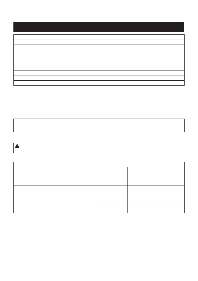
SPECIFICATIONS
Model DLS713
Blade diameter 190 mm
Hole (arbor) diameter (country specic) 20 mm or 15.88 mm
Max. kerf thickness of the saw blade 2.2 mm
Max. Miter angle Left 47° , Right 57°
Max. Bevel angle Left 45°, Right 5°
No load speed 2200 min-1
Dimensions (L x W x H) 655 mm x 430 mm x 454 mm
Net weight 12.2 - 14.3 kg
Rated voltage D.C. 18 V
• Due to our continuing program of research and development, the specications herein are subject to change
without notice.
• Specications may differ from country to country.
• The weight may differ depending on the attachment(s), including the battery cartridge. The lightest and heavi-
est combination, according to EPTA-Procedure 01/2014, are shown in the table.
Applicable battery cartridge and charger
Battery cartridge BL1815N / BL1820 / BL1820B / BL1830 / BL1830B / BL1840 /
BL1840B / BL1850 / BL1850B / BL1860B
Charger DC18RC / DC18RD / DC18RE / DC18SD / DC18SE / DC18SF
• Some of the battery cartridges and chargers listed above may not be available depending on your region of
residence.
WARNING: Only use the battery cartridges and chargers listed above. Use of any other battery cartridges
and chargers may cause injury and/or re.
Max. Cutting capacities (H x W) with blade 190 mm in diameter.
Miter angle Bevel angle
45° (left) 0° 5° (right)
0° 25 mm x 300 mm 52 mm x 300 mm 40 mm x 300 mm
----- * 60 mm x 265 mm
(Note 1)
-----
45° (left and right) 25 mm x 212 mm 52 mm x 212 mm -----
----- * 60 mm x 185 mm
(Note 2)
-----
57° (right) ----- 52 mm x 163 mm -----
----- * 60 mm x 145 mm
(Note 3)
-----
(Note)
* mark indicates that a wood facing with the following thickness is used.
1: When using a wood facing 20 mm thickness
2: When using a wood facing 15 mm thickness
3: When using a wood facing 10 mm thickness

11 ENGLISH
Symbols
The followings show the symbols used for the equipment.
Be sure that you understand their meaning before use.
Read instruction manual.
To avoid injury from ying debris, keep
holding the saw head down, after making
cuts, until the blade has come to a com-
plete stop.
When performing slide cut, rst pull car-
riage fully and press down handle, then
push carriage toward the guide fence.
Do not place hand or ngers close to the
blade.
Always set SUB-FENCE to left position
when performing left bevel cuts. Failure to
do so may cause serious injury to operator.
Ni-MH
Li-ion
Only for EU countries
Do not dispose of electric equipment or
battery pack together with household waste
material!
In observance of the European Directives,
on Waste Electric and Electronic
Equipment and Batteries and Accumulators
and Waste Batteries and Accumulators
and their implementation in accordance
with national laws, electric equipment and
batteries and battery pack(s) that have
reached the end of their life must be col-
lected separately and returned to an envi-
ronmentally compatible recycling facility.
Intended use
The tool is intended for accurate straight and miter
cutting in wood.
Do not use the saw to cut other than wood.
Noise
The typical A-weighted noise level determined accord-
ing to EN62841-3-9:
Sound pressure level (LpA) : 88 dB(A)
Sound power level (LWA) : 98 dB (A)
Uncertainty (K) : 3 dB(A)
NOTE:
The declared noise emission value(s) has been
measured in accordance with a standard test method
and may be used for comparing one tool with another.
NOTE:
The declared noise emission value(s) may
also be used in a preliminary assessment of exposure.
WARNING: Wear ear protection.
WARNING:
The noise emission during actual
use of the power tool can differ from the declared val-
ue(s) depending on the ways in which the tool is used
especially what kind of workpiece is processed.
WARNING:
Be sure to identify safety measures
to protect the operator that are based on an estima-
tion of exposure in the actual conditions of use (tak-
ing account of all parts of the operating cycle such
as the times when the tool is switched off and when
it is running idle in addition to the trigger time).
Vibration
The vibration total value (tri-axial vector sum) deter-
mined according to EN62841-3-9:
Vibration emission (ah) : 2.5 m/s2or less
Uncertainty (K) : 1.5 m/s2
NOTE: The declared vibration total value(s) has been
measured in accordance with a standard test method
and may be used for comparing one tool with another.
NOTE: The declared vibration total value(s) may also
be used in a preliminary assessment of exposure.
WARNING:
The vibration emission during actual
use of the power tool can differ from the declared val-
ue(s) depending on the ways in which the tool is used
especially what kind of workpiece is processed.
WARNING:
Be sure to identify safety measures
to protect the operator that are based on an estima-
tion of exposure in the actual conditions of use (tak-
ing account of all parts of the operating cycle such
as the times when the tool is switched off and when
it is running idle in addition to the trigger time).
EC Declaration of Conformity
For European countries only
The EC declaration of conformity is included as Annex A
to this instruction manual.
SAFETY WARNINGS
General power tool safety warnings
WARNING: Read all safety warnings, instruc-
tions, illustrations and specications provided
with this power tool. Failure to follow all instructions
listed below may result in electric shock, re and/or
serious injury.
Save all warnings and instruc-
tions for future reference.
The term "power tool" in the warnings refers to your
mains-operated (corded) power tool or battery-operated
(cordless) power tool.
Safety instructions for mitre saws
1.
Mitre saws are intended to cut wood or wood-like
products, they cannot be used with abrasive cut-off
wheels for cutting ferrous material such as bars, rods,
studs, etc. Abrasive dust causes moving parts such as the
lower guard to jam. Sparks from abrasive cutting will burn
the lower guard, the kerf insert and other plastic parts.
2.
Use clamps to support the workpiece whenever pos-
sible. If supporting the workpiece by hand, you must
always keep your hand at least 100 mm from either side
of the saw blade. Do not use this saw to cut pieces that
are too small to be securely clamped or held by hand. If
your hand is placed too close to the saw blade, there is an
increased risk of injury from blade contact.

12 ENGLISH
3. The workpiece must be stationary and
clamped or held against both the fence and the
table. Do not feed the workpiece into the blade
or cut "freehand" in any way. Unrestrained
or moving workpieces could be thrown at high
speeds, causing injury.
4. Push the saw through the workpiece. Do not
pull the saw through the workpiece. To make
a cut, raise the saw head and pull it out over
the workpiece without cutting, start the motor,
press the saw head down and push the saw
through the workpiece. Cutting on the pull stroke
is likely to cause the saw blade to climb on top
of the workpiece and violently throw the blade
assembly towards the operator.
5. Never cross your hand over the intended line
of cutting either in front or behind the saw
blade. Supporting the workpiece "cross handed"
i.e. holding the workpiece to the right of the saw
blade with your left hand or vice versa is very
dangerous.
► Fig.1
6. Do not reach behind the fence with either hand
closer than 100 mm from either side of the saw
blade, to remove wood scraps, or for any other
reason while the blade is spinning. The proxim-
ity of the spinning saw blade to your hand may not
be obvious and you may be seriously injured.
7. Inspect your workpiece before cutting. If the
workpiece is bowed or warped, clamp it with
the outside bowed face toward the fence.
Always make certain that there is no gap
between the workpiece, fence and table along
the line of the cut. Bent or warped workpieces
can twist or shift and may cause binding on the
spinning saw blade while cutting. There should be
no nails or foreign objects in the workpiece.
8. Do not use the saw until the table is clear of all
tools, wood scraps, etc., except for the work-
piece. Small debris or loose pieces of wood or
other objects that contact the revolving blade can
be thrown with high speed.
9.
Cut only one workpiece at a time. Stacked multiple
workpieces cannot be adequately clamped or braced
and may bind on the blade or shift during cutting.
10. Ensure the mitre saw is mounted or placed on
a level, rm work surface before use. A level
and rm work surface reduces the risk of the mitre
saw becoming unstable.
11. Plan your work. Every time you change the
bevel or mitre angle setting, make sure the
adjustable fence is set correctly to support the
workpiece and will not interfere with the blade
or the guarding system. Without turning the tool
"ON" and with no workpiece on the table, move
the saw blade through a complete simulated cut to
assure there will be no interference or danger of
cutting the fence.
12. Provide adequate support such as table exten-
sions, saw horses, etc. for a workpiece that is
wider or longer than the table top. Workpieces
longer or wider than the mitre saw table can tip
if not securely supported. If the cut-off piece or
workpiece tips, it can lift the lower guard or be
thrown by the spinning blade.
13.
Do not use another person as a substitute for a
table extension or as additional support. Unstable
support for the workpiece can cause the blade to bind
or the workpiece to shift during the cutting operation
pulling you and the helper into the spinning blade.
14. The cut-off piece must not be jammed or
pressed by any means against the spinning
saw blade. If conned, i.e. using length stops, the
cut-off piece could get wedged against the blade
and thrown violently.
15. Always use a clamp or a xture designed to
properly support round material such as rods
or tubing. Rods have a tendency to roll while
being cut, causing the blade to "bite" and pull the
work with your hand into the blade.
16. Let the blade reach full speed before contact-
ing the workpiece. This will reduce the risk of the
workpiece being thrown.
17. If the workpiece or blade becomes jammed,
turn the mitre saw off. Wait for all moving
parts to stop and disconnect the plug from
the power source and/or remove the battery
pack. Then work to free the jammed material.
Continued sawing with a jammed workpiece could
cause loss of control or damage to the mitre saw.
18.
After nishing the cut, release the switch, hold
the saw head down and wait for the blade to stop
before removing the cut-off piece. Reaching with
your hand near the coasting blade is dangerous.
19.
Hold the handle rmly when making an incom-
plete cut or when releasing the switch before the
saw head is completely in the down position. The
braking action of the saw may cause the saw head to
be suddenly pulled downward, causing a risk of injury.
20. Only use the saw blade with the diameter that
is marked on the tool or specied in the man-
ual. Use of an incorrectly sized blade may affect
the proper guarding of the blade or guard opera-
tion which could result in serious personal injury.
21. Only use the saw blades that are marked with
a speed equal or higher than the speed marked
on the tool.
22. (For European countries only)
Always use the blade which conforms to EN847-1.
Additional instructions
1. Make workshop kid proof with padlocks.
2. Never stand on the tool. Serious injury could
occur if the tool is tipped or if the cutting tool is
unintentionally contacted.
3. Never leave the tool running unattended. Turn
the power off. Do not leave tool until it comes
to a complete stop.
4.
Do not operate saw without guards in place.
Check blade guard for proper closing before each
use. Do not operate saw if blade guard does not
move freely and close instantly. Never clamp or
tie the blade guard into the open position.
5. Keep hands out of path of saw blade. Avoid
contact with any coasting blade. It can still
cause severe injury.
6.
To reduce the risk of injury, return carriage to the
full rear position after each crosscut operation.
7. Always secure all moving portions before
carrying the tool.

13 ENGLISH
8. Stopper pin which locks the cutter head down
is for carrying and storage purposes only and
not for any cutting operations.
9. Check the blade carefully for cracks or dam-
age before operation. Replace cracked or dam-
aged blade immediately. Gum and wood pitch
hardened on blades slows saw and increases
potential for kickback. Keep blade clean by
rst removing it from tool, then cleaning it with
gum and pitch remover, hot water or kerosene.
Never use gasoline to clean blade.
10. While making a slide cut, KICKBACK can
occur. KICKBACK occurs when the blade
binds in the workpiece during a cutting oper-
ation and the saw blade is driven rapidly
towards the operator. Loss of control and seri-
ous personal injury can result. If blade begins
to bind during a cutting operation, do not con-
tinue to cut and release switch immediately.
11. Use only anges specied for this tool.
12.
Be careful not to damage the arbor, anges (espe-
cially the installing surface) or bolt. Damage to
these parts could result in blade breakage.
13. Make sure that the turn base is properly
secured so it will not move during operation.
Use the holes in the base to fasten the saw to a
stable work platform or bench. NEVER use tool
where operator positioning would be awkward.
14. Make sure the shaft lock is released before the
switch is turned on.
15. Be sure that the blade does not contact the
turn base in the lowest position.
16. Hold the handle rmly. Be aware that the saw
moves up or down slightly during start-up and
stopping.
17. Make sure the blade is not contacting the
workpiece before the switch is turned on.
18. Before using the tool on an actual workpiece,
let it run for a while. Watch for vibration or
wobbling that could indicate poor installation
or a poorly balanced blade.
19. Stop operation immediately if you notice any-
thing abnormal.
20. Do not attempt to lock the trigger in the "ON"
position.
21. Always use accessories recommended in this
manual. Use of improper accessories such as
abrasive wheels may cause an injury.
22.
Some material contains chemicals which may be
toxic. Take caution to prevent dust inhalation and
skin contact. Follow material supplier safety data.
Additional safety rules for the laser
1. LASER RADIATION, DO NOT STARE INTO THE
BEAM OR VIEW DIRECTLY WITH OPTICAL
INSTRUMENTS, CLASS 2M LASER PRODUCT.
SAVE THESE INSTRUCTIONS.
WARNING: DO NOT let comfort or familiarity
with product (gained from repeated use) replace
strict adherence to safety rules for the subject
product. MISUSE or failure to follow the safety
rules stated in this instruction manual may cause
serious personal injury.
Important safety instructions for
battery cartridge
1. Before using battery cartridge, read all instruc-
tions and cautionary markings on (1) battery
charger, (2) battery, and (3) product using
battery.
2. Do not disassemble battery cartridge.
3. If operating time has become excessively
shorter, stop operating immediately. It may
result in a risk of overheating, possible burns
and even an explosion.
4. If electrolyte gets into your eyes, rinse them
out with clear water and seek medical atten-
tion right away. It may result in loss of your
eyesight.
5. Do not short the battery cartridge:
(1) Do not touch the terminals with any con-
ductive material.
(2) Avoid storing battery cartridge in a con-
tainer with other metal objects such as
nails, coins, etc.
(3) Do not expose battery cartridge to water
or rain.
A battery short can cause a large current
ow, overheating, possible burns and even a
breakdown.
6. Do not store the tool and battery cartridge in
locations where the temperature may reach or
exceed 50 °C (122 °F).
7. Do not incinerate the battery cartridge even if
it is severely damaged or is completely worn
out. The battery cartridge can explode in a re.
8. Be careful not to drop or strike battery.
9. Do not use a damaged battery.
10. The contained lithium-ion batteries are subject
to the Dangerous Goods Legislation require-
ments.
For commercial transports e.g. by third parties,
forwarding agents, special requirement on pack-
aging and labeling must be observed.
For preparation of the item being shipped, consult-
ing an expert for hazardous material is required.
Please also observe possibly more detailed
national regulations.
Tape or mask off open contacts and pack up the
battery in such a manner that it cannot move
around in the packaging.
11. Follow your local regulations relating to dis-
posal of battery.
12. Use the batteries only with the products
specied by Makita. Installing the batteries to
non-compliant products may result in a re, exces-
sive heat, explosion, or leak of electrolyte.
SAVE THESE INSTRUCTIONS.
CAUTION: Only use genuine Makita batteries.
Use of non-genuine Makita batteries, or batteries that
have been altered, may result in the battery bursting
causing res, personal injury and damage. It will
also void the Makita warranty for the Makita tool and
charger.

14 ENGLISH
Tips for maintaining maximum
battery life
1. Charge the battery cartridge before completely
discharged. Always stop tool operation and
charge the battery cartridge when you notice
less tool power.
2. Never recharge a fully charged battery car-
tridge. Overcharging shortens the battery
service life.
3. Charge the battery cartridge with room tem-
perature at 10 °C - 40 °C (50 °F - 104 °F). Let
a hot battery cartridge cool down before
charging it.
4. Charge the battery cartridge if you do not use
it for a long period (more than six months).
INSTALLATION
Bench mounting
► Fig.2: 1. Stopper pin
When the tool is shipped, the handle is locked in the
lowered position by the stopper pin. Release the stop-
per pin by simultaneously applying a slight downward
pressure on the handle and pulling the stopper pin.
WARNING:
• Ensure that the tool will not move on the
supporting surface. Movement of the miter
saw on the supporting surface while cutting may
result in loss of control and serious personal
injury.
► Fig.3: 1. Bolt
This tool should be bolted with two bolts to a level and
stable surface using the bolt holes provided in the tool's
base. This will help prevent tipping and possible injury.
► Fig.4: 1. Adjusting bolt
Turn the adjusting bolt clockwise or counterclockwise
so that it comes into a contact with the oor surface to
keep the tool stable.
Installing the holders and holder
assemblies
NOTE: In some countries, the holders and holder
assemblies may not be included in the tool package
as standard accessory.
The holders and the holder assemblies support work-
pieces horizontally.
Tighten the fence shafts to the holder assemblies using
the hex wrench.
► Fig.5: 1. Holder 2. Holder assembly 3. Fence shaft
4. Hex wrench
Install the holders and the holder assemblies on both
side as shown in the gure. When installing, make sure
that the fence shaft is in the same line of the guide
fence when installed to the tool.
► Fig.6: 1. Holder 2. Holder assembly 3. Screw
Then tighten the screws rmly to secure the holders and
the holder assemblies.
FUNCTIONAL DESCRIPTION
WARNING:
• Always be sure that the tool is switched off
and the battery cartridge is removed before
adjusting or checking the functions on the
tool. Failure to switch off and remove the bat-
tery cartridge may result in serious personal
injury from accidental start-up.
Installing or removing battery cartridge
CAUTION: Always switch off the tool before
installing or removing of the battery cartridge.
CAUTION: Hold the tool and the battery car-
tridge rmly when installing or removing battery
cartridge. Failure to hold the tool and the battery
cartridge rmly may cause them to slip off your hands
and result in damage to the tool and battery cartridge
and a personal injury.
► Fig.7: 1. Red indicator 2. Button 3. Battery cartridge
To remove the battery cartridge, slide it from the tool
while sliding the button on the front of the cartridge.
To install the battery cartridge, align the tongue on the
battery cartridge with the groove in the housing and slip
it into place. Insert it all the way until it locks in place
with a little click. If you can see the red indicator on the
upper side of the button, it is not locked completely.
CAUTION: Always install the battery cartridge
fully until the red indicator cannot be seen. If not,
it may accidentally fall out of the tool, causing injury to
you or someone around you.
CAUTION: Do not install the battery cartridge
forcibly. If the cartridge does not slide in easily, it is
not being inserted correctly.
Battery protection system (Lithium-
ion battery with star marking)
► Fig.8: 1. Star marking
Lithium-ion batteries with a star marking are equipped
with a protection system. This system automatically
cuts off power to the tool to extend battery life.
The tool will automatically stop during operation if the
tool and/or battery are placed under one of the following
conditions:
• Overloaded:
The tool is operated in a manner that causes
it to draw an abnormally high current.
In this situation, release the trigger switch on
the tool and stop the application that caused
the tool to become overloaded. Then pull the
trigger switch again to restart.
If the tool does not start, the battery is over-
heated. In this situation, let the battery cool
before pulling the trigger switch again.
• Low battery voltage:
The remaining battery capacity is too low
and the tool will not operate. In this situation,
remove and recharge the battery.

15 ENGLISH
Indicating the remaining battery
capacity
Only for battery cartridges with the indicator
► Fig.9: 1. Indicator lamps 2. Check button
Press the check button on the battery cartridge to indi-
cate the remaining battery capacity. The indicator lamps
light up for a few seconds.
Indicator lamps Remaining
capacity
Lighted Off Blinking
75% to 100%
50% to 75%
25% to 50%
0% to 25%
Charge the
battery.
The battery
may have
malfunctioned.
NOTE: Depending on the conditions of use and the
ambient temperature, the indication may differ slightly
from the actual capacity.
Blade guard
► Fig.10: 1. Blade guard
When lowering the handle, the blade guard rises auto-
matically. The guard is spring loaded so it returns to
its original position when the cut is completed and the
handle is raised.
WARNING:
• Never defeat or remove the blade guard or
the spring which attaches to the guard. An
exposed blade as a result of defeated guarding
may result in serious personal injury during
operation.
In the interest of your personal safety, always maintain
the blade guard in good condition. Any irregular opera-
tion of the blade guard should be corrected immediately.
Check to assure spring loaded return action of guard.
WARNING:
• Never use the tool if the blade guard or
spring are damaged, faulty or removed.
Operation of the tool with a damaged, faulty or
removed guard may result in serious personal
injury.
Cleaning
► Fig.11: 1. Blade guard
If the transparent blade guard becomes dirty, or sawdust
adheres to it in such a way that the blade and/or workpiece
is no longer easily visible, remove the battery cartridge and
clean the guard carefully with a damp cloth. Do not use
solvents or any petroleum-based cleaners on the plastic
guard because this may cause damage to the guard.
For cleaning, raise the blade guard by referring to
"Installing or removing saw blade".
After cleaning, make sure to return the blade and center
cover and tighten the hex socket bolt.
1. Make sure that the tool is switched off and the
battery cartridges are removed.
2. Turn the hex socket bolt counterclockwise using
the supplied hex wrench with holding the center cover.
3. Raise the blade guard and center cover.
4. When cleaning is complete, return the center
cover and tighten the hex socket bolt by performing the
steps above in reverse.
WARNING: Do not remove spring holding
blade guard. If guard becomes damaged in course
of time or UV light exposure, contact a Makita ser-
vice center for replacement. DO NOT DEFEAT OR
REMOVE GUARD.
Positioning kerf board
► Fig.12: 1. Thumb screw 2. Kerf board
► Fig.13: 1. Saw blade 2. Blade teeth 3. Kerf board
4. Left bevel cut 5. Straight cut
This tool is provided with the kerf boards in the turn
base to minimize tearing on the exit side of a cut. The
kerf boards are factory adjusted so that the saw blade
does not contact the kerf boards. Before use, adjust the
kerf boards as follows:
First, remove the battery cartridge. Loosen all the
screws (2 each on left and right) securing the kerf
boards. Re-tighten them only to the extent that the kerf
boards can still be easily moved by hand. Lower the
handle fully and push in the stopper pin to lock the han-
dle in the lowered position. Loosen two clamp screws
which secure the slide poles. Pull the carriage toward
you fully. Adjust the kerf boards so that the kerf boards
just contact the sides of the blade teeth. Tighten the
front screws (do not tighten rmly). Push the carriage
toward the guide fence fully and adjust the kerf boards
so that the kerf boards just contact the sides of blade
teeth. Tighten the rear screws (do not tighten rmly).
After adjusting the kerf boards, release the stopper
pin and raise the handle. Then tighten all the screws
securely.
NOTICE:
• After setting the bevel angle ensure that the
kerf boards are adjusted properly. Correct
adjustment of the kerf boards will help provide
proper support of the workpiece minimizing work-
piece tear out.

16 ENGLISH
Maintaining maximum cutting capacity
► Fig.14:
1. Adjusting bolt 2. Guide fence 3. Turn base
► Fig.15: 1. Top surface of turn table 2. Periphery of
blade 3. Guide fence
This tool is factory adjusted to provide the maximum
cutting capacity for a 190 mm saw blade.
Remove the battery cartridge before any adjustment is
attempted. When installing a new blade, always check the lower
limit position of the blade and if necessary, adjust it as follows:
First, remove the battery cartridge. Push the carriage
toward the guide fence fully and lower the handle com-
pletely. Use the hex wrench to turn the adjusting bolt until
the periphery of the blade extends slightly below the top
surface of the turn base at the point where the front face
of the guide fence meets the top surface of the turn base.
With the battery cartridge removed, rotate the blade
by hand while holding the handle all the way down to
be sure that the blade does not contact any part of the
lower base. Re-adjust slightly, if necessary.
WARNING:
•
After installing a new blade and with the battery
cartridge removed, always be sure that the
blade does not contact any part of the lower
base when the handle is lowered completely. If
a blade makes contact with the base it may cause
kickback and result in serious personal injury.
Stopper arm
► Fig.16: 1. Adjusting screw 2. Stopper arm
The lower limit position of the blade can be easily
adjusted with the stopper arm. To adjust it, move the
stopper arm in the direction of the arrow as shown in the
gure. Adjust the adjusting screw so that the blade stops
at the desired position when lowering the handle fully.
Sub-fence
Country specic
CAUTION:
When performing left bevel cuts, ip the
sub-fence outward. Otherwise, it may contact the blade or a
part of the tool, and may result in serious injury to the operator.
► Fig.17: 1. Sub-fence
This tool is equipped with the sub-fence. Usually position the sub-
fence inside. However, when performing left bevel cuts, ip it outward.
Adjusting the miter angle
► Fig.18: 1. Turn base 2. Lock lever 3. Miter scale
4. Pointer 5. Grip
Loosen the grip by turning counterclockwise. Turn the turn base
while pressing down the lock lever. When you have moved the
grip to the position where the pointer points to the desired angle
on the miter scale, securely tighten the grip clockwise.
CAUTION:
• After changing the miter angle, always secure
the turn base by tightening the grip rmly.
NOTICE:
• When turning the turn base, be sure to raise the
handle fully.
Adjusting the bevel angle
► Fig.19: 1. Lever 2. Release button
► Fig.20: 1. Pointer 2. Bevel scale 3. Arm
To adjust the bevel angle, loosen the lever at the rear of
the tool counterclockwise.
Push the handle to the left to tilt the saw blade until the
pointer points to the desired angle on the bevel scale.
Then tighten the lever clockwise rmly to secure the arm.
To tilt the blade to the right, push the release button at
the rear of the tool while tilting the blade slightly to the
left after loosening the lever. With the release button
depressed, tilt the saw blade to the right.
CAUTION:
• After changing the bevel angle, always secure
the arm by tightening the lever clockwise.
NOTICE:
• When tilting the saw blade be sure the handle is
fully raised.
• When changing bevel angles, be sure to position
the kerf boards appropriately as explained in the
"Positioning kerf boards" section.
Adjusting the lever position
► Fig.21: 1. Lever 2. Screw
The lever can be repositioned at every angle 30° when
the lever does not provide full tightening.
Loosen and remove the screw that secures the lever at the rear
of the tool. Remove the lever and install it again so that it is
slightly above the level. Secure the lever with the screw rmly.
Switch action
WARNING: Before installing the battery car-
tridge on the tool, always check to see that the
switch trigger actuates properly and returns to
the "OFF" position when released. Operating a tool
with a switch that does not actuate properly can lead
to loss of control and serious personal injury.
WARNING: Do not use a lock with a shank or
cable any smaller than 6.35 mm (1/4") in diameter.
A smaller shank or cable may not properly lock the
tool in the off position and unintentional operation
may occur resulting in serious personal injury.
WARNING:
NEVER use tool without a fully oper-
ative switch trigger. Any tool with an inoperative switch
is HIGHLY DANGEROUS and must be repaired before
further usage or serious personal injury may occur.
WARNING: For your safety, this tool is equipped
with a lock-off button which prevents the tool from
unintended starting. NEVER use the tool if it runs
when you simply pull the switch trigger without
pressing the lock-off button. A switch in need of
repair may result in unintentional operation and seri-
ous personal injury. Return tool to a Makita service
center for proper repairs BEFORE further usage.
WARNING: NEVER defeat the lock-off button
by taping down or some other means. A switch with
a negated lock-off button may result in unintentional
operation and serious personal injury.

17 ENGLISH
NOTICE: Do not pull the switch trigger hard
without pressing in the lock-off button. This can
cause switch breakage.
To prevent the switch trigger from being accidentally
pulled, a lock-off button is provided. To start the tool,
press in the lock-off button and pull the switch trigger.
Release the switch trigger to stop.
A hole is provided in the switch trigger for insertion of a
padlock to lock the tool off.
► Fig.22: 1. Lock-off button 2. Switch trigger 3. Hole
for padlock
ASSEMBLY
WARNING:
• Always be sure that the tool is switched off
and the battery cartridge is removed before
working on the tool. Failure to switch off and
remove the battery cartridge may result in seri-
ous personal injury.
Hex wrench storage
► Fig.23: 1. Wrench holder 2. Hex wrench
The hex wrench is stored as shown in the gure. When
the hex wrench is needed it can be pulled out of the
wrench holder.After using the hex wrench it can be
stored by returning it to the wrench holder.
Installing or removing saw blade
► Fig.24: 1. Stopper pin
WARNING:
• Always be sure that the tool is switched off
and the battery cartridge is removed before
installing or removing the blade. Accidental
start up of the tool may result in serious per-
sonal injury.
CAUTION:
• Use only the Makita hex wrench provided to
install or remove the blade. Failure to do so may
result in overtightening or insufcient tightening
of the hex socket bolt. This could cause an
injury.
Lock the handle in the raised position by pushing in the
stopper pin.
► Fig.25: 1. Center cover 2. Hex socket bolt 3. Hex
wrench 4. Safety cover
To remove the blade, use the hex wrench to loosen the
hex socket bolt holding the center cover by turning it
counterclockwise. Raise the blade guard and center
cover.
► Fig.26: 1. Shaft lock 2. Arrow 3. Blade case 4. Hex
wrench 5. Hex socket bolt
Press the shaft lock to lock the spindle and use the hex
wrench to loosen the hex socket bolt clockwise. Then
remove the hex socket bolt, outer ange and blade.
NOTE:
• If the inner ange is removed be sure to install
it on the spindle with its protrusion facing away
from the blade. If the ange is installed incor-
rectly the ange will rub against the machine.
► Fig.27: 1. Outer ange 2. Saw blade 3. Inner ange
4. Hex socket bolt(left-handed) 5. Spindle
► Fig.28:
1. Blade case 2. Arrow 3. Arrow 4. Saw blade
To install the blade, mount it carefully onto the spindle,
making sure that the direction of the arrow on the sur-
face of the blade matches the direction of the arrow on
the blade case. Install the outer ange and hex socket
bolt, and then use the hex wrench to tighten the hex
socket bolt (left-handed) securely counterclockwise
while pressing the shaft lock.
Return the blade guard and center cover to its original
position. Then tighten the hex socket bolt clockwise
to secure the center cover. Release the handle from
the raised position by pulling the stopper pin. Lower
the handle to make sure that the blade guard moves
properly. Make sure the shaft lock has released spindle
before making cut.
For tool with the inner ange for
15.88 mm hole-diameter saw blade
Country specic
Mount the inner ange with its recessed side facing
outward onto the mounting shaft and then place circu-
lar saw blade (with the ring attached if needed), outer
ange and hex bolt.
For tool without the ring
► Fig.29: 1. Outer ange 2. Saw blade 3. Inner ange
4. Hex socket bolt (left-handed) 5. Spindle
For tool with the ring
► Fig.30: 1. Outer ange 2. Saw blade 3. Inner ange
4. Hex socket bolt (left-handed) 5. Ring
6. Spindle
WARNING: If the ring is needed to mount the
blade onto the spindle, always be sure that the
correct ring for the blade's arbor hole you intend
to use is installed between the inner and the outer
anges. Use of the incorrect arbor hole ring may
result in the improper mounting of the blade causing
blade movement and severe vibration resulting in
possible loss of control during operation and in seri-
ous personal injury.
For tool with the inner ange for
other than 20 mm or 15.88 mm hole-
diameter saw blade
Country specic
The inner ange has a certain diameter of a blade
mounting part on one side of it and a different diameter
of blade mounting part on the other side. Choose a
correct side on which blade mounting part ts into the
saw blade hole perfectly.
► Fig.31: 1. Outer ange 2. Saw blade 3. Inner ange
4. Hex socket bolt (left-handed) 5. Spindle
6. Blade mounting part

18 ENGLISH
CAUTION: Make sure that the blade mounting
part "a" on the inner ange that is positioned
outside ts into the saw blade hole "a" perfectly.
Mounting the blade on the wrong side can result in
the dangerous vibration.
Connecting a vacuum cleaner
When you wish to perform clean cutting operation,
connect a Makita vacuum cleaner.
► Fig.32
Dust bag (accessory)
► Fig.33: 1. Dust bag 2. Dust nozzle 3. Fastener
To attach the fastener, align the top end of the fastener
with the triangular mark on the dust bag.
The use of the dust bag makes cutting operations
cleaner and dust collection easier. To attach the dust
bag, t it onto the dust nozzle.
When the dust bag is about half full, remove the dust
bag from the tool and pull the fastener out. Empty
the dust bag of its contents, tapping it lightly so as to
remove particles adhering to the insides which might
hamper further collection.
Securing workpiece
WARNING:
• It is extremely important to always secure
the workpiece correctly with the proper type
of vise. Failure to do so may result in serious
personal injury and cause damage to the tool
and/or the workpiece.
• After a cutting operation do not raise the
blade until it has come to a complete stop.
The raising of a coasting blade may result in
serious personal injury and damage to the
workpiece.
• When cutting a workpiece that is longer
than the support base of the saw, the mate-
rial should be supported the entire length
beyond the support base and at the same
height to keep the material level. Proper
workpiece support will help avoid blade pinch
and possible kickback which may result in seri-
ous personal injury. Do not rely solely on the
vertical vise and/or horizontal vise to secure the
workpiece. Thin material tends to sag. Support
workpiece over its entire length to avoid blade
pinch and possible KICKBACK.
► Fig.34: 1. Support 2. Turn base
Vertical vise
► Fig.35: 1. Vise arm 2. Vise rod 3. Guide fence
4. Holder 5. Holder assembly 6. Vise knob
7. Screw
The vertical vise can be installed in two positions on
either the left or right side of the guide fence or the
holder assembly. Insert the vise rod into the hole in
the guide fence or the holder assembly and tighten the
screw to secure the vise rod.
Position the vise arm according to the thickness and
shape of the workpiece and secure the vise arm by
tightening the screw. If the screw to secure the vise arm
contacts the guide fence, install the screw on the oppo-
site side of vise arm. Make sure that no part of the tool
contacts the vise when lowering the handle fully and
pulling or pushing the carriage all the way. If some part
contacts the vise, re-position the vise.
Press the workpiece at against the guide fence and the
turn base. Position the workpiece at the desired cutting
position and secure it rmly by tightening the vise knob.
WARNING:
• The workpiece must be secured rmly
against the turn base and guide fence with
the vise during all operations. If the workpiece
is not properly secured against the fence the
material may move during the cutting operation
causing possible damage to the blade, causing
the material to be thrown and loss of control
resulting in serious personal injury.
Horizontal vise (optional accessory)
► Fig.36:
1. Vise knob 2. Projection 3. Vise shaft 4. Base
The horizontal vise can be installed on the left side of
the base. By turning the vise knob counterclockwise, the
screw is released and the vise shaft can be moved rap-
idly in and out. By turning the vise knob clockwise, the
screw remains secured. To grip the workpiece, turn the
vise knob gently clockwise until the projection reaches
its topmost position, then fasten securely. If the vise
knob is forced in or pulled out while being turned clock-
wise, the projection may stop at an angle. In this case,
turn the vise knob back counterclockwise until the screw
is released, before turning again gently clockwise.
The maximum width of the workpiece which can be
secured by the horizontal vise is 120 mm.
WARNING:
• Grip the workpiece only when the projection
is at the topmost position. Failure to do so
may result in insufcient securing of the work-
piece. This could cause the workpiece to be
thrown, cause damage to the blade or cause the
loss of control, which can result in PERSONAL
INJURY.
Holders and holder assembly
(optional accessories)
CAUTION: For the tool equipped with the hold-
ers and the holder assemblies as standard acces-
sories, this type of use is not permitted due to the
country regulations.
► Fig.37: 1. Holder 2. Holder assembly
The holders and the holder assembly can be installed
on either side as a convenient means of supporting
workpieces horizontally. Install them as shown in the
gure. Then tighten the screws rmly to secure the
holders and the holder assembly.
When cutting long workpieces, use the holder-rod
assembly (optional accessory). It consists of two holder
assemblies and two rods 12.
► Fig.38: 1. Holder assembly 2. Rod 12

19 ENGLISH
WARNING:
• Always support a long workpiece so it is
level with the top surface of the turn base for
an accurate cut and to prevent dangerous
loss of tool control. Proper workpiece support
will help avoid blade pinch and possible kick-
back which may result in serious personal injury.
OPERATION
NOTICE:
• Before use, be sure to release the handle from the
lowered position by pulling the stopper pin.
• Do not apply excessive pressure on the handle
when cutting. Too much force may result in over-
load of the motor and/or decreased cutting ef-
ciency. Push down handle with only as much force
as is necessary for smooth cutting and without
signicant decrease in blade speed.
• Gently press down the handle to perform the cut. If
the handle is pressed down with force or if lateral
force is applied, the blade will vibrate and leave a
mark (saw mark) in the workpiece and the preci-
sion of the cut will be impaired.
• During a slide cut, gently push the carriage toward
the guide fence without stopping. If the carriage
movement is stopped during the cut, a mark will
be left in the workpiece and the precision of the
cut will be impaired.
WARNING:
• Make sure the blade is not contacting the
workpiece, etc. before the switch is turned
on.
Turning the tool on with the blade in contact with
the workpiece may result in kickback and seri-
ous personal injury.
Press cutting (cutting small
workpieces)
► Fig.39: 1. Thumb screw 2. Holder assembly
Workpieces up to 52 mm high and 97 mm wide
can be cut in the following manner.
Push the carriage toward the guide fence fully and
tighten two clamp screws which secure the slide poles
clockwise to secure the carriage. Secure the workpiece
with the proper type of vise. Switch on the tool without the
blade making any contact and wait until the blade attains
full speed before lowering. Then gently lower the handle
to the fully lowered position to cut the workpiece. When
the cut is completed, switch off the tool and WAIT UNTIL
THE BLADE HAS COME TO A COMPLETE STOP before
returning the blade to its fully elevated position.
WARNING:
• Firmly tighten two clamping screws which
secure the slide poles clockwise so that the
carriage will not move during operation.
Insufcient tightening of the locking screw may
cause possible kickback which may result in
serious personal injury.
Slide (push) cutting (cutting wide
workpieces)
► Fig.40: 1. Thumb screw 2. Holder assembly
Loosen two clamp screws which secure the slide poles
counterclockwise so that the carriage can slide freely.
Secure the workpiece with the proper type of vise. Pull
the carriage toward you fully. Switch on the tool without
the blade making any contact and wait until the blade
attains full speed. Press the handle down and PUSH
THE CARRIAGE TOWARD THE GUIDE FENCE AND
THROUGH THE WORKPIECE. When the cut is com-
pleted, switch off the tool and WAIT UNTIL THE BLADE
HAS COME TO A COMPLETE STOP before returning
the blade to its fully elevated position.
WARNING:
• Whenever performing a slide cut, rst pull
the carriage full towards you and press the
handle all the way down, then push the car-
riage toward the guide fence. Never start the
cut with the carriage not pulled fully toward
you. If you perform the slide cut without the
carriage pulled fully toward you unexpected
kickback may occur and serious personal injury
may result.
• Never attempt to perform a slide cut by
pulling the carriage towards you. Pulling the
carriage towards you while cutting may cause
unexpected kickback resulting in possible seri-
ous personal injury.
• Never perform the slide cut with the handle
locked in the lowered position.
• Never loosen the knob which secures the
carriage while the blade is rotating. A loose
carriage while cutting may cause unexpected
kickback resulting in possible in serious per-
sonal injury.
Miter cutting
Refer to the previously covered "Adjusting the miter
angle".
Bevel cut
► Fig.41: 1. Holder assembly
Loosen the lever and tilt the saw blade to set the bevel
angle (Refer to the previously covered "Adjusting the
bevel angle"). Be sure to retighten the lever rmly to
secure the selected bevel angle safely. Secure the
workpiece with a vise. Make sure the carriage is pulled
all the way back toward the operator. Switch on the
tool without the blade making any contact and wait
until the blade attains full speed. Then gently lower
the handle to the fully lowered position while applying
pressure in parallel with the blade and PUSH THE
CARRIAGE TOWARD THE GUIDE FENCE TO CUT
THE WORKPIECE. When the cut is completed, switch
off the tool and WAIT UNTIL THE BLADE HAS COME
TO A COMPLETE STOP before returning the blade to
its fully elevated position.

20 ENGLISH
WARNING:
• After setting the blade for a bevel cut, before
operating the tool ensure that the carriage
and blade will have free travel through-
out the entire range of the intended cut.
Interruption of the carriage or blade travel during
the cutting operation may result in kickback and
serious personal injury.
• While making a bevel cut keep hands out of
the path of the blade. The angle of the blade
may confuse the operator as to the actual blade
path while cutting and contact with the blade will
result in serious personal injury.
• The blade should not be raised until it has
come to a complete stop. During a bevel cut
the piece cut off may come to rest against the
blade. If the blade is raised while it is rotating
the cut-off piece maybe ejected by the blade
causing the material to fragment which may
result in serious personal injury.
NOTICE:
• When pressing down the handle, apply pressure
in parallel with the blade. If a force is applied
perpendicularly to the turn base or if the pressure
direction is changed during a cut, the precision of
the cut will be impaired.
CAUTION:
• (Only for European countries) always set the
sub-fence outside when performing left bevel
cuts.
Compound cutting
Compound cutting is the process in which a bevel
angle is made at the same time in which a miter angle
is being cut on a workpiece. Compound cutting can be
performed at the angle shown in the table.
Miter angle
Left and Right 45
Right 50
Right 55
Right 57
Bevel angle
Left 0 - 45
Left 0 - 40
Left 0 - 30
Left 0 - 25
When performing compound cutting, refer to "Press
cutting", "Slide cutting", "Miter cutting" and "Bevel cut"
explanations.
Cutting crown and cove moldings
Crown and cove moldings can be cut on a compound
miter saw with the moldings laid at on the turn base.
► Fig.42: 1. 52/38° type crown molding 2. 45° type
crown molding 3. 45° type cove molding
There are two common types of crown moldings and
one type of cove moldings; 52/38° wall angle crown
molding, 45° wall angle crown molding and 45° wall
angle cove molding. See illustrations.
(1) (2) (3) (4)
1 2
Fig.A
1. Inside corner 2. Outside corner
► Fig.43: 1. Inside corner 2. Outside corner
There are crown and cove molding joints which are
made to t "Inside" 90° corners ((1) and (2) in Fig. A)
and "Outside" 90° corners ((3) and (4) in Fig. A).
Measuring
Measure the wall length and adjust workpiece on table to cut
wall contact edge to desired length. Always make sure that cut
workpiece length at the back of the workpiece is the same
as wall length. Adjust cut length for angle of cut. Always use
several pieces for test cuts to check the saw angles.
When cutting crown and cove moldings, set the bevel
angle and miter angle as indicated in the table (A) and
position the moldings on the top surface of the saw
base as indicated in the table (B).
In the case of left bevel cut
Molding
position in
Fig. A
Bevel angle Miter angle
For outside
corner
For inside
corner
52/38° type 45° type
Right 31.6°
45° type
Left 33.9° Left 30°
52/38° type
Left 31.6° Left 35.3°
Right 35.3°
Right 35.3°Right 31.6°
(1)
(2)
(3)
(4)
Table (A)
Molding
position in
Fig. A
Molding edge against
guide fence
(1) Ceiling contact edge should
be against guide fence.
Ceiling contact edge should
be against guide fence.
For
outside
corner
Finished piece
will be on the
Left side of
blade.
Finished piece
will be on the
Right side of
blade.
For inside
corner
Wall contact edge should be
against guide fence.
Finished piece
(2)
(3)
(4)
Table (B)
EXAMPLE In the case of cutting 52/38° type crown
molding for position (1) in Fig. A:
•
Tilt and secure bevel angle setting to 33.9° LEFT.
•
Adjust and secure miter angle setting to 31.6° RIGHT.
•
Lay crown molding with its broad back (hidden)
surface down on the turn base with its CEILING
CONTACT EDGE against the guide fence on the saw.
• The nished piece to be used will always be
on the LEFT side of the blade after the cut has
been made.
Other manuals for DLS713
7
Table of contents
Languages:
Other Makita Saw manuals

Makita
Makita LF1000 User manual

Makita
Makita MLT100 User manual

Makita
Makita LS1019 User manual

Makita
Makita LS1220 User manual

Makita
Makita PB002G User manual

Makita
Makita JR002G User manual

Makita
Makita DLS714 User manual

Makita
Makita LF1000 User manual

Makita
Makita DSD180 User manual

Makita
Makita 5007MGA Quick start guide

Makita
Makita 2107F User manual

Makita
Makita JR3051T User manual

Makita
Makita JR002GZ User manual

Makita
Makita LS1018 User manual

Makita
Makita LS1018 User manual

Makita
Makita MT560 User manual

Makita
Makita 5008MGA User manual

Makita
Makita LS1013 Quick start guide

Makita
Makita 5007NB User manual

Makita
Makita 5620DWA Quick start guide