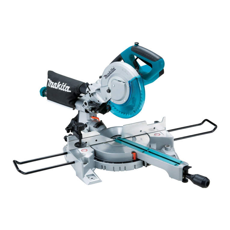
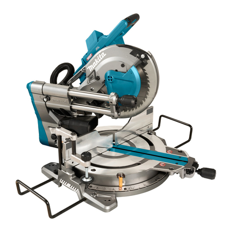
Makita DLS713 User manual

INSTRUCTION MANUAL
MANUEL D'INSTRUCTION
MANUAL DE INSTRUCCIONES
Cordless Slide Compound Miter Saw
Scie Radiale Sans Fil
Sierra de Inglete Telescópica
Inalámbrica
DLS713
IMPORTANT: Read Before Using.
IMPORTANT : Lire avant usage.
IMPORTANTE: Lea antes de usar.

2ENGLISH
ENGLISH (Original instructions)
SPECIFICATIONS
Model DLS713
Blade diameter 190 mm (7-1/2")
Hole (arbor) diameter 15.88 mm (5/8")
Max. kerf thickness of the saw blade 2.2 mm (3/32")
Max. Miter angle Left 47° , Right 57°
Max. Bevel angle Left 45°, Right 5°
No load speed (RPM) 2,200 /min
Dimensions (L x W x H) 655 mm x 430 mm x 454 mm (25-3/4" x 17" x 17-7/8")
Rated voltage D.C. 18 V
Net weight 12.2 - 14.3 kg (27.0 - 31.6 lbs)
• Duetoourcontinuingprogramofresearchanddevelopment,thespecicationshereinaresubjecttochange
without notice.
• Specicationsmaydifferfromcountrytocountry.
• Theweightmaydifferdependingontheattachment(s),includingthebatterycartridge.Thelightestandheavi-
est combination, according to EPTA-Procedure 01/2014, are shown in the table.
Applicable battery cartridge and charger
Batterycartridge
BL1815N / BL1820B / BL1830 / BL1830B / BL1840B / BL1850B / BL1860B
Charger DC18RC / DC18RD / DC18RE / DC18SD / DC18SE / DC18SF
• Someofthebatterycartridgesandchargerslistedabovemaynotbeavailabledependingonyourregionof
residence.
WARNING: Only use the battery cartridges and chargers listed above.Useofanyotherbatterycartridges
andchargersmaycauseinjuryand/orre.
Max. Cutting capacities (H x W) with blade 190 mm (7-1/2") in diameter.
Miter angle Bevel angle
45° (left) 0° 5° (right)
0° 25 mm x 300 mm
(1" x 11 - 3/4")
52 mm x 300 mm
(2 - 1/16" x 11 - 3/4")
40 mm x 300 mm
(1 - 9/16" x 11 - 3/4")
----- * 60 mm x 265 mm
(Note 1)
(2-3/8" x 10-3/8")
-----
45° (left and right) 25 mm x 212 mm
(1" x 8 - 3/8")
52 mm x 212 mm
(2 - 1/16" x 8 - 3/8")
-----
----- * 60 mm x 185 mm
(Note 2)
(2-3/8" x 7-1/4")
-----
57° (right) ----- 52 mm x 163 mm
(2 - 1/16" x 6 - 3/8")
-----
----- * 60 mm x 145 mm
(Note 3)
(2-3/8" x 5-3/4")
-----
(Note)
* mark indicates that a wood facing with the following thickness is used.
1: When using a wood facing 20 mm thickness
2: When using a wood facing 15 mm thickness
3: When using a wood facing 10 mm thickness

3ENGLISH
SAFETY WARNINGS
General power tool safety warnings
WARNING:
Read all safety warnings, instruc-
tions, illustrations and specications provided with this
power tool. Failure to follow all instructions listed below
mayresultinelectricshock,reand/orseriousinjury.
Save all warnings and instruc-
tions for future reference.
Theterm"powertool"inthewarningsreferstoyour
mains-operated(corded)powertoolorbattery-operated
(cordless) power tool.
Work area safety
1. Keep work area clean and well lit. Cluttered or
dark areas invite accidents.
2. Do not operate power tools in explosive atmo-
spheres, such as in the presence of ammable
liquids, gases or dust. Power tools create sparks
whichmayignitethedustorfumes.
3. Keep children and bystanders away while
operating a power tool. Distractions can cause
youtolosecontrol.
Electrical Safety
1. Power tool plugs must match the outlet. Never
modify the plug in any way. Do not use any
adapter plugs with earthed (grounded) power
tools. Unmodiedplugsandmatchingoutletswill
reduce risk of electric shock.
2. Avoid body contact with earthed or grounded
surfaces, such as pipes, radiators, ranges and
refrigerators. There is an increased risk of elec-
tricshockifyourbodyisearthedorgrounded.
3. Do not expose power tools to rain or wet con-
ditions. Water entering a power tool will increase
the risk of electric shock.
4. Do not abuse the cord. Never use the cord for
carrying, pulling or unplugging the power tool.
Keep cord away from heat, oil, sharp edges
or moving parts. Damaged or entangled cords
increase the risk of electric shock.
5.
When operating a power tool outdoors, use an exten-
sion cord suitable for outdoor use. Use of a cord suit-
able for outdoor use reduces the risk of electric shock.
6. If operating a power tool in a damp location is
unavoidable, use a ground fault circuit inter-
rupter (GFCI) protected supply. Use of a GFCI
reduces the risk of electric shock.
7.
Power tools can produce electromagnetic elds
(EMF) that are not harmful to the user. However,
users of pacemakers and other similar medical
devices should contact the maker of their device and/
or doctor for advice before operating this power tool.
Personal Safety
1. Stay alert, watch what you are doing and use
common sense when operating a power tool.
Do not use a power tool while you are tired or
under the inuence of drugs, alcohol or med-
ication. A moment of inattention while operating
powertoolsmayresultinseriouspersonalinjury.
2. Use personal protective equipment. Always
wear eye protection. Protective equipment such
asdustmask,non-skidsafetyshoes,hardhat,or
hearing protection used for appropriate conditions
willreducepersonalinjuries.
3. Prevent unintentional starting. Ensure the
switch is in the off-position before connecting
to power source and/or battery pack, picking
up or carrying the tool.Carryingpowertoolswith
yourngerontheswitchorenergisingpowertools
that have the switch on invites accidents.
4. Remove any adjusting key or wrench before
turning the power tool on.Awrenchorakeyleft
attachedtoarotatingpartofthepowertoolmay
resultinpersonalinjury.
5. Do not overreach. Keep proper footing and
balance at all times. This enables better control
of the power tool in unexpected situations.
6. Dress properly. Do not wear loose clothing or
jewellery. Keep your hair, clothing and gloves
away from moving parts.Looseclothes,jewel-
leryorlonghaircanbecaughtinmovingparts.
7. If devices are provided for the connection of
dust extraction and collection facilities, ensure
these are connected and properly used. Use of
dust collection can reduce dust-related hazards.
8.
Do not let familiarity gained from frequent use
of tools allow you to become complacent and
ignore tool safety principles. A careless action can
causesevereinjurywithinafractionofasecond.
9. Always wear protective goggles to protect
your eyes from injury when using power tools.
The goggles must comply with ANSI Z87.1 in
the USA.
It is an employer's responsibility to enforce
the use of appropriate safety protective equip-
ments by the tool operators and by other per-
sons in the immediate working area.
Power tool use and care
1. Do not force the power tool. Use the correct
power tool for your application. The correct
powertoolwilldothejobbetterandsaferatthe
rate for which it was designed.
2. Do not use the power tool if the switch does
not turn it on and off.Anypowertoolthatcannot
be controlled with the switch is dangerous and
must be repaired.
3. Disconnect the plug from the power source
and/or remove the battery pack, if detachable,
from the power tool before making any adjust-
ments, changing accessories, or storing power
tools.Suchpreventivesafetymeasuresreduce
theriskofstartingthepowertoolaccidentally.
4. Store idle power tools out of the reach of chil-
dren and do not allow persons unfamiliar with
the power tool or these instructions to operate
the power tool. Power tools are dangerous in the
hands of untrained users.
5. Maintain power tools and accessories. Check
for misalignment or binding of moving parts,
breakage of parts and any other condition that
may affect the power tool’s operation. If dam-
aged, have the power tool repaired before use.
Manyaccidentsarecausedbypoorlymaintained
power tools.
4ENGLISH
6. Keep cutting tools sharp and clean.Properly
maintained cutting tools with sharp cutting edges
arelesslikelytobindandareeasiertocontrol.
7. Use the power tool, accessories and tool bits
etc. in accordance with these instructions, tak-
ing into account the working conditions and
the work to be performed. Use of the power tool
for operations different from those intended could
result in a hazardous situation.
8. Keep handles and grasping surfaces dry,
clean and free from oil and grease.Slippery
handles and grasping surfaces do not allow for
safe handling and control of the tool in unexpected
situations.
9. When using the tool, do not wear cloth work
gloves which may be entangled. The entangle-
mentofclothworkglovesinthemovingpartsmay
resultinpersonalinjury.
Battery tool use and care
1. Recharge only with the charger specied by
the manufacturer. A charger that is suitable for
onetypeofbatterypackmaycreateariskofre
whenusedwithanotherbatterypack.
2. Use power tools only with specically desig-
nated battery packs.Useofanyotherbattery
packsmaycreateariskofinjuryandre.
3. When battery pack is not in use, keep it away
from other metal objects, like paper clips,
coins, keys, nails, screws or other small metal
objects, that can make a connection from one
terminal to another.Shortingthebatterytermi-
nalstogethermaycauseburnsorare.
4. Under abusive conditions, liquid may be
ejected from the battery; avoid contact. If con-
tact accidentally occurs, ush with water. If
liquid contacts eyes, additionally seek medical
help.Liquidejectedfromthebatterymaycause
irritation or burns.
5. Do not use a battery pack or tool that is dam-
aged or modied.Damagedormodiedbatteries
mayexhibitunpredictablebehaviourresultingin
re,explosionorriskofinjury.
6. Do not expose a battery pack or tool to re or
excessive temperature.Exposuretoreortem-
peratureabove130°Cmaycauseexplosion.
7. Follow all charging instructions and do not
charge the battery pack or tool outside the
temperature range specied in the instruc-
tions.Chargingimproperlyorattemperatures
outsidethespeciedrangemaydamagethe
batteryandincreasetheriskofre.
Service
1. Have your power tool serviced by a qualied
repair person using only identical replacement
parts.Thiswillensurethatthesafetyofthepower
tool is maintained.
2. Never service damaged battery packs. Service
ofbatterypacksshouldonlybeperformedbythe
manufacturer or authorized service providers.
3. Follow instruction for lubricating and chang-
ing accessories.
4. Do not modify or attempt to repair the appli-
ance or the battery pack except as indicated in
the instructions for use and care.
Safety instructions for mitre saws
1. Mitre saws are intended to cut wood or wood-
like products, they cannot be used with abra-
sive cut-off wheels for cutting ferrous material
such as bars, rods, studs, etc. Abrasive dust
causes moving parts such as the lower guard to
jam.Sparksfromabrasivecuttingwillburnthe
lower guard, the kerf insert and other plastic parts.
2.
Use clamps to support the workpiece whenever
possible. If supporting the workpiece by hand,
you must always keep your hand at least 100
mm from either side of the saw blade. Do not
use this saw to cut pieces that are too small to
be securely clamped or held by hand.Ifyour
hand is placed too close to the saw blade, there is
anincreasedriskofinjuryfrombladecontact.
3.
The workpiece must be stationary and clamped
or held against both the fence and the table. Do
not feed the workpiece into the blade or cut "free-
hand" in any way. Unrestrained or moving work-
piecescouldbethrownathighspeeds,causinginjury.
4. Push the saw through the workpiece. Do not
pull the saw through the workpiece. To make
a cut, raise the saw head and pull it out over
the workpiece without cutting, start the motor,
press the saw head down and push the saw
through the workpiece. Cutting on the pull stroke
islikelytocausethesawbladetoclimbontop
oftheworkpieceandviolentlythrowtheblade
assemblytowardstheoperator.
5.
Never cross your hand over the intended line of
cutting either in front or behind the saw blade.
Supporting the workpiece "cross handed" i.e. hold-
ing the workpiece to the right of the saw blade with
yourlefthandorviceversaisverydangerous.
6. Do not reach behind the fence with either hand
closer than 100 mm from either side of the saw
blade, to remove wood scraps, or for any other
reason while the blade is spinning. The proxim-
ityofthespinningsawbladetoyourhandmaynot
beobviousandyoumaybeseriouslyinjured.
7. Inspect your workpiece before cutting. If the
workpiece is bowed or warped, clamp it with
the outside bowed face toward the fence.
Always make certain that there is no gap
between the workpiece, fence and table along
the line of the cut. Bent or warped workpieces
cantwistorshiftandmaycausebindingonthe
spinning saw blade while cutting. There should be
nonailsorforeignobjectsintheworkpiece.

5ENGLISH
8. Do not use the saw until the table is clear of all
tools, wood scraps, etc., except for the work-
piece. Small debris or loose pieces of wood or
otherobjectsthatcontacttherevolvingbladecan
be thrown with high speed.
9.
Cut only one workpiece at a time. Stacked multiple
workpiecescannotbeadequatelyclampedorbraced
andmaybindonthebladeorshiftduringcutting.
10. Ensure the mitre saw is mounted or placed on
a level, rm work surface before use. A level
andrmworksurfacereducestheriskofthemitre
saw becoming unstable.
11. Plan your work. Every time you change the
bevel or mitre angle setting, make sure the
adjustable fence is set correctly to support the
workpiece and will not interfere with the blade
or the guarding system. Without turning the tool
"ON" and with no workpiece on the table, move
the saw blade through a complete simulated cut to
assure there will be no interference or danger of
cutting the fence.
12. Provide adequate support such as table exten-
sions, saw horses, etc. for a workpiece that is
wider or longer than the table top. Workpieces
longer or wider than the mitre saw table can tip
ifnotsecurelysupported.Ifthecut-offpieceor
workpiece tips, it can lift the lower guard or be
thrownbythespinningblade.
13. Do not use another person as a substitute for
a table extension or as additional support.
Unstable support for the workpiece can cause the
blade to bind or the workpiece to shift during the
cuttingoperationpullingyouandthehelperinto
the spinning blade.
14. The cut-off piece must not be jammed or
pressed by any means against the spinning
saw blade.Ifconned,i.e.usinglengthstops,the
cut-off piece could get wedged against the blade
andthrownviolently.
15. Always use a clamp or a xture designed to
properly support round material such as rods
or tubing.Rodshaveatendencytorollwhile
being cut, causing the blade to "bite" and pull the
workwithyourhandintotheblade.
16. Let the blade reach full speed before contact-
ing the workpiece. This will reduce the risk of the
workpiece being thrown.
17. If the workpiece or blade becomes jammed,
turn the mitre saw off. Wait for all moving
parts to stop and disconnect the plug from
the power source and/or remove the battery
pack. Then work to free the jammed material.
Continuedsawingwithajammedworkpiececould
cause loss of control or damage to the mitre saw.
18. After nishing the cut, release the switch,
hold the saw head down and wait for the blade
to stop before removing the cut-off piece.
Reachingwithyourhandnearthecoastingblade
is dangerous.
19. Hold the handle rmly when making an incom-
plete cut or when releasing the switch before
the saw head is completely in the down posi-
tion.Thebrakingactionofthesawmaycause
thesawheadtobesuddenlypulleddownward,
causingariskofinjury.
20. Only use the saw blade with the diameter that
is marked on the tool or specied in the man-
ual.Useofanincorrectlysizedblademayaffect
the proper guarding of the blade or guard opera-
tionwhichcouldresultinseriouspersonalinjury.
21. Only use the saw blades that are marked with
a speed equal or higher than the speed marked
on the tool.
22. Always select the correct saw blade for the
material to be cut. Do not use the saw blade to
cut materials other than those specied.
Additional instructions
1. Intended use
The tool is intended for accurate straight and
miter cutting in wood. Do not use the saw to
cut other than wood.
2. Make workshop kid proof with padlocks.
3. Never stand on the tool.Seriousinjurycould
occur if the tool is tipped or if the cutting tool is
unintentionallycontacted.
4. Never leave the tool running unattended. Turn
the power off. Do not leave tool until it comes
to a complete stop.
5. Do not operate saw without guards in place.
Check blade guard for proper closing before
each use. Do not operate saw if blade guard
does not move freely and close instantly.
Never clamp or tie the blade guard into the
open position.
6. Keep hands out of path of saw blade. Avoid
contact with any coasting blade. It can still
cause severe injury.
7.
To reduce the risk of injury, return carriage to the
full rear position after each crosscut operation.
8. Always secure all moving portions before
carrying the tool.
9. Stopper pin which locks the cutter head down
is for carrying and storage purposes only and
not for any cutting operations.
10. Check the blade carefully for cracks or dam-
age before operation. Replace cracked or dam-
aged blade immediately. Gum and wood pitch
hardened on blades slows saw and increases
potential for kickback. Keep blade clean by
rst removing it from tool, then cleaning it with
gum and pitch remover, hot water or kerosene.
Never use gasoline to clean blade.
11. While making a slide cut, KICKBACK can
occur. KICKBACK occurs when the blade
binds in the workpiece during a cutting oper-
ation and the saw blade is driven rapidly
towards the operator. Loss of control and seri-
ous personal injury can result. If blade begins
to bind during a cutting operation, do not con-
tinue to cut and release switch immediately.
12. Use only anges specied for this tool.
13.
Be careful not to damage the arbor, anges (espe-
cially the installing surface) or bolt. Damage to
these parts could result in blade breakage.
14. Make sure that the turn base is properly
secured so it will not move during operation.
Use the holes in the base to fasten the saw to a
stable work platform or bench. NEVER use tool
where operator positioning would be awkward.

6ENGLISH
15. Make sure the shaft lock is released before the
switch is turned on.
16. Be sure that the blade does not contact the
turn base in the lowest position.
17. Hold the handle rmly. Be aware that the saw
moves up or down slightly during start-up and
stopping.
18. Make sure the blade is not contacting the
workpiece before the switch is turned on.
19. Before using the tool on an actual workpiece,
let it run for a while. Watch for vibration or
wobbling that could indicate poor installation
or a poorly balanced blade.
20. Stop operation immediately if you notice any-
thing abnormal.
21.
Do not attempt to lock the trigger in the "ON" position.
22. Always use accessories recommended in this
manual. Use of improper accessories such as
abrasive wheels may cause an injury.
23. Some material contains chemicals which may
be toxic. Take caution to prevent dust inhala-
tion and skin contact. Follow material supplier
safety data.
SAVE THESE INSTRUCTIONS.
WARNING: DO NOT let comfort or familiarity
with product (gained from repeated use) replace
strict adherence to safety rules for the subject
product. MISUSE or failure to follow the safety
rules stated in this instruction manual may cause
serious personal injury.
Important safety instructions for
battery cartridge
1.
Before using battery cartridge, read all instruc-
tions and cautionary markings on (1) battery char-
ger, (2) battery, and (3) product using battery.
2. Do not disassemble battery cartridge.
3. If operating time has become excessively
shorter, stop operating immediately. It may
result in a risk of overheating, possible burns
and even an explosion.
4.
If electrolyte gets into your eyes, rinse them out
with clear water and seek medical attention right
away. It may result in loss of your eyesight.
5. Do not short the battery cartridge:
(1) Do not touch the terminals with any con-
ductive material.
(2) Avoid storing battery cartridge in a con-
tainer with other metal objects such as
nails, coins, etc.
(3) Do not expose battery cartridge to water
or rain.
A battery short can cause a large current
ow, overheating, possible burns and even a
breakdown.
6. Do not store the tool and battery cartridge in
locations where the temperature may reach or
exceed 50 °C (122 °F).
7. Do not incinerate the battery cartridge even if
it is severely damaged or is completely worn
out. The battery cartridge can explode in a re.
8. Be careful not to drop or strike battery.
9. Do not use a damaged battery.
10. The contained lithium-ion batteries are subject
to the Dangerous Goods Legislation require-
ments.
Forcommercialtransportse.g.bythirdparties,
forwarding agents, special requirement on pack-
aging and labeling must be observed.
For preparation of the item being shipped, consult-
ing an expert for hazardous material is required.
Pleasealsoobservepossiblymoredetailed
national regulations.
Tape or mask off open contacts and pack up the
batteryinsuchamannerthatitcannotmove
around in the packaging.
11. Follow your local regulations relating to dis-
posal of battery.
12. Use the batteries only with the products
specied by Makita. Installing the batteries to
non-compliantproductsmayresultinare,exces-
siveheat,explosion,orleakofelectrolyte.
SAVE THESE INSTRUCTIONS.
CAUTION: Only use genuine Makita batteries.
Use of non-genuine Makita batteries, or batteries that
havebeenaltered,mayresultinthebatterybursting
causingres,personalinjuryanddamage.Itwill
alsovoidtheMakitawarrantyfortheMakitatooland
charger.
Tips for maintaining maximum
battery life
1. Charge the battery cartridge before completely
discharged. Always stop tool operation and
charge the battery cartridge when you notice
less tool power.
2. Never recharge a fully charged battery car-
tridge. Overcharging shortens the battery
service life.
3. Charge the battery cartridge with room tem-
perature at 10 °C - 40 °C (50 °F - 104 °F). Let
a hot battery cartridge cool down before
charging it.
4. Charge the battery cartridge if you do not use
it for a long period (more than six months).
Symbols
Thefollowingsshowthesymbolsusedfortool.
volts
direct current
no load speed
revolutions or reciprocation per minute
Donotplacehandorngersclosetothe
blade.

7ENGLISH
INSTALLATION
Bench mounting
When the tool is shipped, the handle is locked in the
loweredpositionbythestopperpin.Releasethestop-
perpinbysimultaneouslyapplyingaslightdownward
pressure on the handle and pulling the stopper pin.
1
►1. Stopper pin
WARNING:
• Ensure that the tool will not move on the
supporting surface. Movement of the miter
sawonthesupportingsurfacewhilecuttingmay
result in loss of control and serious personal
injury.
This tool should be bolted with two bolts to a level and
stable surface using the bolt holes provided in the tool's
base.Thiswillhelppreventtippingandpossibleinjury.
1
181 mm 181 mm
ɸ8.5x 2
►1. Bolt
Turntheadjustingboltclockwiseorcounterclockwise
sothatitcomesintoacontactwiththeoorsurfaceto
keep the tool stable.
1
►1.Adjustingbolt
Installing the holders and holder assemblies
NOTE: In some countries, the holders and holder
assembliesmaynotbeincludedinthetoolpackage
asstandardaccessory.
The holders and the holder assemblies support work-
pieceshorizontally.
Tighten the fence shafts to the holder assemblies using
the hex wrench.
4
3
1
2
►
1. Holder 2.Holderassembly3. Fence shaft 4. Hex wrench
Install the holders and the holder assemblies on both side as
showninthegure.Wheninstalling,makesurethatthefenceshaft
is in the same line of the guide fence when installed to the tool.
1
2
3
►1. Holder 2.Holderassembly3. Screw

8ENGLISH
Thentightenthescrewsrmlytosecuretheholdersand
the holder assemblies.
FUNCTIONAL
DESCRIPTION
WARNING:
• Always be sure that the tool is switched off
and the battery cartridge is removed before
adjusting or checking the functions on the
tool. Failure to switch off and remove the bat-
terycartridgemayresultinseriouspersonal
injuryfromaccidentalstart-up.
Installing or removing battery
cartridge
CAUTION: Always switch off the tool before
installing or removing of the battery cartridge.
CAUTION: Hold the tool and the battery car-
tridge rmly when installing or removing battery
cartridge.Failuretoholdthetoolandthebattery
cartridgermlymaycausethemtoslipoffyourhands
andresultindamagetothetoolandbatterycartridge
andapersonalinjury.
1
2
3
►1. Red indicator 2. Button 3.Batterycartridge
Toremovethebatterycartridge,slideitfromthetool
while sliding the button on the front of the cartridge.
Toinstallthebatterycartridge,alignthetongueonthe
batterycartridgewiththegrooveinthehousingandslip
itintoplace.Insertitallthewayuntilitlocksinplace
withalittleclick.Ifyoucanseetheredindicatoronthe
uppersideofthebutton,itisnotlockedcompletely.
CAUTION: Always install the battery cartridge
fully until the red indicator cannot be seen. If not,
itmayaccidentallyfalloutofthetool,causinginjuryto
youorsomeonearoundyou.
CAUTION: Do not install the battery cartridge
forcibly.Ifthecartridgedoesnotslideineasily,itis
notbeinginsertedcorrectly.
Battery protection system (Lithium-
ion battery with star marking)
1
►1. Star marking
Lithium-ion batteries with a star marking are equipped
withaprotectionsystem.Thissystemautomatically
cutsoffpowertothetooltoextendbatterylife.
Thetoolwillautomaticallystopduringoperationifthe
tooland/orbatteryareplacedunderoneofthefollowing
conditions:
• Overloaded:
The tool is operated in a manner that causes
ittodrawanabnormallyhighcurrent.
In this situation, release the trigger switch on
the tool and stop the application that caused
the tool to become overloaded. Then pull the
trigger switch again to restart.
Ifthetooldoesnotstart,thebatteryisover-
heated.Inthissituation,letthebatterycool
before pulling the trigger switch again.
• Lowbatteryvoltage:
Theremainingbatterycapacityistoolow
and the tool will not operate. In this situation,
removeandrechargethebattery.
Indicating the remaining battery
capacity
Only for battery cartridges with the indicator
1
2
►1. Indicator lamps 2. Check button
Pressthecheckbuttononthebatterycartridgetoindi-
catetheremainingbatterycapacity.Theindicatorlamps
light up for a few seconds.

9ENGLISH
Indicator lamps Remaining
capacity
Lighted Off Blinking
75% to 100%
50% to 75%
25% to 50%
0% to 25%
Charge the
battery.
Thebattery
mayhave
malfunctioned.
NOTE: Depending on the conditions of use and the
ambienttemperature,theindicationmaydifferslightly
fromtheactualcapacity.
Blade guard
1
►1. Blade guard
When lowering the handle, the blade guard rises automat-
ically.Theguardisspringloadedsoitreturnstoitsoriginal
position when the cut is completed and the handle is raised.
WARNING:
• Never defeat or remove the blade guard or
the spring which attaches to the guard. An
exposed blade as a result of defeated guarding
mayresultinseriouspersonalinjuryduring
operation.
Intheinterestofyourpersonalsafety,alwaysmaintain
thebladeguardingoodcondition.Anyirregularopera-
tionofthebladeguardshouldbecorrectedimmediately.
Check to assure spring loaded return action of guard.
WARNING:
• Never use the tool if the blade guard or
spring are damaged, faulty or removed.
Operationofthetoolwithadamaged,faultyor
removedguardmayresultinseriouspersonal
injury.
Cleaning
1
►1. Blade guard
Ifthetransparentbladeguardbecomesdirty,orsaw-
dustadherestoitinsuchawaythatthebladeand/or
workpieceisnolongereasilyvisible,removethebattery
cartridgeandcleantheguardcarefullywithadamp
cloth.Donotusesolventsoranypetroleum-based
cleanersontheplasticguardbecausethismaycause
damage to the guard.
Forcleaning,raisethebladeguardbyreferringto
"Installing or removing saw blade".
After cleaning, make sure to return the blade and center
cover and tighten the hex socket bolt.
1. Make sure that the tool is switched off and the
batterycartridgesareremoved.
2. Turn the hex socket bolt counterclockwise using
the supplied hex wrench with holding the center cover.
3. Raise the blade guard and center cover.
4. When cleaning is complete, return the center
coverandtightenthehexsocketboltbyperformingthe
steps above in reverse.
WARNING: Do not remove spring holding
blade guard. If guard becomes damaged in course
of time or UV light exposure, contact a Makita ser-
vice center for replacement. DO NOT DEFEAT OR
REMOVE GUARD.
Positioning kerf board
1
2
►1. Thumb screw 2. Kerf board

10 ENGLISH
12
3
45
►1. Saw blade 2. Blade teeth 3. Kerf board 4. Left
bevel cut 5. Straight cut
This tool is provided with the kerf boards in the turn
base to minimize tearing on the exit side of a cut. The
kerfboardsarefactoryadjustedsothatthesawblade
doesnotcontactthekerfboards.Beforeuse,adjustthe
kerf boards as follows:
First,removethebatterycartridge.Loosenallthe
screws (2 each on left and right) securing the kerf
boards.Re-tightenthemonlytotheextentthatthekerf
boardscanstillbeeasilymovedbyhand.Lowerthe
handlefullyandpushinthestopperpintolockthehan-
dle in the lowered position. Loosen two clamp screws
which secure the slide poles. Pull the carriage toward
youfully.Adjustthekerfboardssothatthekerfboards
justcontactthesidesofthebladeteeth.Tightenthe
frontscrews(donottightenrmly).Pushthecarriage
towardtheguidefencefullyandadjustthekerfboards
sothatthekerfboardsjustcontactthesidesofblade
teeth.Tightentherearscrews(donottightenrmly).
Afteradjustingthekerfboards,releasethestopper
pin and raise the handle. Then tighten all the screws
securely.
NOTICE:
• After setting the bevel angle ensure that the
kerf boards are adjusted properly. Correct
adjustmentofthekerfboardswillhelpprovide
proper support of the workpiece minimizing work-
piece tear out.
Maintaining maximum cutting
capacity
1
2
3
►1.Adjustingbolt2. Guide fence 3. Turn base
2
3
1
►1. Top surface of turn table 2.Peripheryofblade
3. Guide fence
Thistoolisfactoryadjustedtoprovidethemaximum
cuttingcapacityfora190mm(7-1/2")sawblade.
Removethebatterycartridgebeforeanyadjustmentis
attempted.Wheninstallinganewblade,alwayscheck
thelowerlimitpositionofthebladeandifnecessary,
adjustitasfollows:
First,removethebatterycartridge.Pushthecarriage
towardtheguidefencefullyandlowerthehandlecom-
pletely.Usethehexwrenchtoturntheadjustingboltuntil
theperipheryofthebladeextendsslightlybelowthetop
surface of the turn base at the point where the front face
of the guide fence meets the top surface of the turn base.
Withthebatterycartridgeremoved,rotatetheblade
byhandwhileholdingthehandleallthewaydownto
besurethatthebladedoesnotcontactanypartofthe
lowerbase.Re-adjustslightly,ifnecessary.
WARNING:
• After installing a new blade and with the
battery cartridge removed, always be sure
that the blade does not contact any part of
the lower base when the handle is lowered
completely. If a blade makes contact with the
baseitmaycausekickbackandresultinserious
personalinjury.
Stopper arm
1
2
►1.Adjustingscrew2. Stopper arm
Thelowerlimitpositionofthebladecanbeeasily
adjustedwiththestopperarm.Toadjustit,movethe
stopper arm in the direction of the arrow as shown in the
gure.Adjusttheadjustingscrewsothatthebladestops
atthedesiredpositionwhenloweringthehandlefully.

11 ENGLISH
Sub-fence
Country specic
CAUTION: When performing left bevel cuts,
ip the sub-fence outward. Otherwise,itmaycon-
tactthebladeorapartofthetool,andmayresultin
seriousinjurytotheoperator.
1
►1. Sub-fence
Thistoolisequippedwiththesub-fence.Usuallyposi-
tion the sub-fence inside. However, when performing
leftbevelcuts,ipitoutward.
Adjusting the miter angle
1
2
34
5
►1. Turn base 2. Lock lever 3. Miter scale 4. Pointer
5. Grip
Loosenthegripbyturningcounterclockwise.Turnthe
turnbasewhilepressingdownthelocklever.Whenyou
have moved the grip to the position where the pointer
pointstothedesiredangleonthemiterscale,securely
tighten the grip clockwise.
CAUTION:
• Afterchangingthemiterangle,alwayssecure
theturnbasebytighteningthegriprmly.
NOTICE:
• When turning the turn base, be sure to raise the
handlefully.
Adjusting the bevel angle
1
2
►1. Lever 2. Release button
1
2
3
►1. Pointer 2. Bevel scale 3. Arm
Toadjustthebevelangle,loosentheleverattherearof
the tool counterclockwise.
Push the handle to the left to tilt the saw blade until the
pointer points to the desired angle on the bevel scale.
Thentightentheleverclockwisermlytosecurethe
arm.
To tilt the blade to the right, push the release button at
therearofthetoolwhiletiltingthebladeslightlytothe
left after loosening the lever. With the release button
depressed, tilt the saw blade to the right.
CAUTION:
• Afterchangingthebevelangle,alwayssecure
thearmbytighteningtheleverclockwise.
NOTICE:
• When tilting the saw blade be sure the handle is
fullyraised.
• When changing bevel angles, be sure to position
thekerfboardsappropriatelyasexplainedinthe
"Positioning kerf boards" section.

12 ENGLISH
Adjusting the lever position
12
►1. Lever 2. Screw
Thelevercanberepositionedateveryangle30°when
the lever does not provide full tightening.
Loosen and remove the screw that secures the lever at
the rear of the tool. Remove the lever and install it again
sothatitisslightlyabovethelevel.Securethelever
withthescrewrmly.
Switch action
WARNING: Before installing the battery car-
tridge on the tool, always check to see that the
switch trigger actuates properly and returns to
the "OFF" position when released. Operating a tool
withaswitchthatdoesnotactuateproperlycanlead
tolossofcontrolandseriouspersonalinjury.
WARNING: Do not use a lock with a shank or
cable any smaller than 6.35 mm (1/4") in diameter.
Asmallershankorcablemaynotproperlylockthe
tool in the off position and unintentional operation
mayoccurresultinginseriouspersonalinjury.
WARNING:
NEVER use tool without a fully oper-
ative switch trigger.Anytoolwithaninoperativeswitch
is HIGHLY DANGEROUS and must be repaired before
furtherusageorseriouspersonalinjurymayoccur.
WARNING:Foryoursafety,thistoolisequipped
with a lock-off button which prevents the tool from
unintended starting. NEVER use the tool if it runs
when you simply pull the switch trigger without
pressing the lock-off button. A switch in need of
repairmayresultinunintentionaloperationandseri-
ouspersonalinjury.ReturntooltoaMakitaservice
center for proper repairs BEFORE further usage.
WARNING: NEVER defeat the lock-off button
by taping down or some other means. A switch with
anegatedlock-offbuttonmayresultinunintentional
operationandseriouspersonalinjury.
NOTICE: Do not pull the switch trigger hard
without pressing in the lock-off button. This can
cause switch breakage.
Topreventtheswitchtriggerfrombeingaccidentallypulled,alock-
off button is provided. To start the tool, press in the lock-off button
and pull the switch trigger. Release the switch trigger to stop.
A hole is provided in the switch trigger for insertion of a
padlock to lock the tool off.
1
2
3
►1. Lock-off button 2. Switch trigger 3. Hole for
padlock
Electric brake
This tool is equipped with an electric blade brake. If the
toolconsistentlyfailstoquicklystopthebladeafterthe
switch trigger is released, have the tool serviced at a
Makita service center.
CAUTION:
• The blade brake system is not a substitute
for the blade guard. Never use tool without a
functioning blade guard. An unguarded blade
mayresultinseriouspersonalinjury.
ASSEMBLY
WARNING:
• Always be sure that the tool is switched off
and the battery cartridge is removed before
working on the tool. Failure to switch off and
removethebatterycartridgemayresultinseri-
ouspersonalinjury.
Hex wrench storage
12
►1. Wrench holder 2. Hex wrench
Thehexwrenchisstoredasshowninthegure.When
the hex wrench is needed it can be pulled out of the
wrench holder. After using the hex wrench it can be
storedbyreturningittothewrenchholder.

13 ENGLISH
Installing or removing saw blade
1
►1. Stopper pin
WARNING:
• Always be sure that the tool is switched off
and the battery cartridge is removed before
installing or removing the blade. Accidental
startupofthetoolmayresultinseriousper-
sonalinjury.
CAUTION:
• UseonlytheMakitahexwrenchprovidedto
installorremovetheblade.Failuretodosomay
resultinovertighteningorinsufcienttightening
of the hex socket bolt. This could cause an
injury.
Lockthehandleintheraisedpositionbypushinginthe
stopper pin.
To remove the blade, use the hex wrench to loosen the
hexsocketboltholdingthecentercoverbyturningit
counterclockwise. Raise the blade guard and center
cover.
1
2
3
4
►1. Center cover 2. Hex socket bolt 3. Hex wrench
4.Safetycover
Press the shaft lock to lock the spindle and use the hex
wrench to loosen the hex socket bolt clockwise. Then
removethehexsocketbolt,outerangeandblade.
1
2
3
4
5
►1. Shaft lock 2. Arrow 3. Blade case 4. Hex wrench
5. Hex socket bolt
NOTE:
• Iftheinnerangeisremovedbesuretoinstall
itonthespindlewithitsprotrusionfacingaway
fromtheblade.Iftheangeisinstalledincor-
rectlytheangewillrubagainstthemachine.
Toinstalltheblade,mountitcarefullyontothespindle,
making sure that the direction of the arrow on the sur-
face of the blade matches the direction of the arrow on
thebladecase.Installtheouterangeandhexsocket
bolt, and then use the hex wrench to tighten the hex
socketbolt(left-handed)securelycounterclockwise
while pressing the shaft lock.
123
45
►1.Outerange2. Saw blade 3.Innerange4. Hex
socket bolt (left-handed) 5. Spindle
1234
►1. Blade case 2. Arrow 3. Arrow 4. Saw blade

14 ENGLISH
Return the blade guard and center cover to its original
position. Then tighten the hex socket bolt clockwise
to secure the center cover. Release the handle from
theraisedpositionbypullingthestopperpin.Lower
the handle to make sure that the blade guard moves
properly.Makesuretheshaftlockhasreleasedspindle
before making cut.
Connecting a vacuum cleaner
Whenyouwishtoperformcleancuttingoperation,
connect a Makita vacuum cleaner.
Dust bag
12
3
►1. Dust bag 2. Dust nozzle 3. Fastener
To attach the fastener, align the top end of the fastener
with the triangular mark on the dust bag.
The use of the dust bag makes cutting operations
cleaner and dust collection easier. To attach the dust
bag,titontothedustnozzle.
When the dust bag is about half full, remove the dust
bagfromthetoolandpullthefastenerout.Empty
thedustbagofitscontents,tappingitlightlysoasto
remove particles adhering to the insides which might
hamper further collection.
Securing workpiece
WARNING:
•
It is extremely important to always secure the
workpiece correctly with the proper type of vise.
Failuretodosomayresultinseriouspersonalinjury
and cause damage to the tool and/or the workpiece.
•
After a cutting operation do not raise the
blade until it has come to a complete stop. The
raisingofacoastingblademayresultinserious
personalinjuryanddamagetotheworkpiece.
• When cutting a workpiece that is longer
than the support base of the saw, the mate-
rial should be supported the entire length
beyond the support base and at the same
height to keep the material level. Proper
workpiece support will help avoid blade pinch
andpossiblekickbackwhichmayresultinseri-
ouspersonalinjury.Donotrelysolelyonthe
vertical vise and/or horizontal vise to secure the
workpiece. Thin material tends to sag. Support
workpiece over its entire length to avoid blade
pinch and possible KICKBACK.
12
►1. Support 2. Turn base
Vertical vise
6
1
3
5
4
2
7
►1. Vise arm 2. Vise rod 3. Guide fence 4. Holder
5.Holderassembly6. Vise knob 7. Screw
The vertical vise can be installed in two positions on
either the left or right side of the guide fence or the
holderassembly.Inserttheviserodintotheholein
theguidefenceortheholderassemblyandtightenthe
screw to secure the vise rod.

15 ENGLISH
Position the vise arm according to the thickness and
shapeoftheworkpieceandsecurethevisearmby
tightening the screw. If the screw to secure the vise arm
contacts the guide fence, install the screw on the oppo-
site side of vise arm. Make sure that no part of the tool
contactsthevisewhenloweringthehandlefullyand
pullingorpushingthecarriagealltheway.Ifsomepart
contacts the vise, re-position the vise.
Presstheworkpieceatagainsttheguidefenceandthe
turn base. Position the workpiece at the desired cutting
positionandsecureitrmlybytighteningtheviseknob.
WARNING:
• The workpiece must be secured rmly
against the turn base and guide fence with
the vise during all operations. If the workpiece
isnotproperlysecuredagainstthefencethe
materialmaymoveduringthecuttingoperation
causing possible damage to the blade, causing
the material to be thrown and loss of control
resultinginseriouspersonalinjury.
Horizontal vise (optional accessory)
1
2
3
4
►1. Vise knob 2.Projection3. Vise shaft 4. Base
The horizontal vise can be installed on the left side of
thebase.Byturningtheviseknobcounterclockwise,
the screw is released and the vise shaft can be moved
rapidlyinandout.Byturningtheviseknobclockwise,
the screw remains secured. To grip the workpiece,
turntheviseknobgentlyclockwiseuntiltheprojection
reachesitstopmostposition,thenfastensecurely.
If the vise knob is forced in or pulled out while being
turnedclockwise,theprojectionmaystopatanangle.
In this case, turn the vise knob back counterclockwise
untilthescrewisreleased,beforeturningagaingently
clockwise.
The maximum width of the workpiece which can be
securedbythehorizontalviseis120mm(4-3/4").
WARNING:
• Grip the workpiece only when the projection
is at the topmost position. Failure to do so
mayresultininsufcientsecuringofthework-
piece. This could cause the workpiece to be
thrown, cause damage to the blade or cause the
loss of control, which can result in PERSONAL
INJURY.
Holders and holder assembly
(optional accessories)
CAUTION: For the tool equipped with the hold-
ers and the holder assemblies as standard acces-
sories,thistypeofuseisnotpermittedduetothe
countryregulations.
12
►1. Holder 2.Holderassembly
Theholdersandtheholderassemblycanbeinstalled
on either side as a convenient means of supporting
workpieceshorizontally.Installthemasshowninthe
gure.Thentightenthescrewsrmlytosecurethe
holdersandtheholderassembly.
When cutting long workpieces, use the holder-rod
assembly(optionalaccessory).Itconsistsoftwoholder
assemblies and two rods 12.
2
1
►1.Holderassembly2. Rod 12
WARNING:
• Always support a long workpiece so it is
level with the top surface of the turn base for
an accurate cut and to prevent dangerous
loss of tool control. Proper workpiece support
will help avoid blade pinch and possible kick-
backwhichmayresultinseriouspersonalinjury.

16 ENGLISH
OPERATION
NOTICE:
• Before use, be sure to release the handle from the
loweredpositionbypullingthestopperpin.
• Donotapplyexcessivepressureonthehandle
whencutting.Toomuchforcemayresultinover-
loadofthemotorand/ordecreasedcuttingef-
ciency.Pushdownhandlewithonlyasmuchforce
asisnecessaryforsmoothcuttingandwithout
signicantdecreaseinbladespeed.
•
Gentlypressdownthehandletoperformthecut.Ifthehan-
dle is pressed down with force or if lateral force is applied,
the blade will vibrate and leave a mark (saw mark) in the
workpiece and the precision of the cut will be impaired.
•
Duringaslidecut,gentlypushthecarriagetowardthe
guide fence without stopping. If the carriage movement
is stopped during the cut, a mark will be left in the work-
piece and the precision of the cut will be impaired.
WARNING:
•
Make sure the blade is not contacting the
workpiece, etc. before the switch is turned on.
Turning the tool on with the blade in contact with
theworkpiecemayresultinkickbackandseri-
ouspersonalinjury.
Press cutting (cutting small workpieces)
1
2
►1. Thumb screw 2.Holderassembly
Workpieces up to 52 mm (2-1/16") high and 97 mm
(3-13/16") wide can be cut in the following manner.
Pushthecarriagetowardtheguidefencefullyandtightentwo
clamp screws which secure the slide poles clockwise to secure
thecarriage.Securetheworkpiecewiththepropertypeof
vise.Switchonthetoolwithouttheblademakinganycontact
and wait until the blade attains full speed before lowering.
Thengentlylowerthehandletothefullyloweredpositiontocut
the workpiece. When the cut is completed, switch off the tool
and WAIT UNTIL THE BLADE HAS COME TO A COMPLETE
STOPbeforereturningthebladetoitsfullyelevatedposition.
WARNING:
• Firmly tighten two clamping screws which
secure the slide poles clockwise so that the
carriage will not move during operation.
Insufcienttighteningofthelockingscrewmay
causepossiblekickbackwhichmayresultin
seriouspersonalinjury.
Slide (push) cutting (cutting wide
workpieces)
1
2
►1. Thumb screw 2.Holderassembly
Loosen two clamp screws which secure the slide poles
counterclockwisesothatthecarriagecanslidefreely.
Securetheworkpiecewiththepropertypeofvise.Pull
thecarriagetowardyoufully.Switchonthetoolwithout
theblademakinganycontactandwaituntiltheblade
attains full speed. Press the handle down and PUSH
THE CARRIAGE TOWARD THE GUIDE FENCE AND
THROUGH THE WORKPIECE. When the cut is com-
pleted, switch off the tool and WAIT UNTIL THE BLADE
HAS COME TO A COMPLETE STOP before returning
thebladetoitsfullyelevatedposition.
WARNING:
• Whenever performing a slide cut, rst pull
the carriage full towards you and press the
handle all the way down, then push the car-
riage toward the guide fence. Never start the
cut with the carriage not pulled fully toward
you.Ifyouperformtheslidecutwithoutthe
carriagepulledfullytowardyouunexpected
kickbackmayoccurandseriouspersonalinjury
mayresult.
• Never attempt to perform a slide cut by
pulling the carriage towards you. Pulling the
carriagetowardsyouwhilecuttingmaycause
unexpected kickback resulting in possible seri-
ouspersonalinjury.
• Never perform the slide cut with the handle
locked in the lowered position.
• Never loosen the knob which secures the
carriage while the blade is rotating. A loose
carriagewhilecuttingmaycauseunexpected
kickback resulting in possible in serious per-
sonalinjury.
Miter cutting
Refertothepreviouslycovered"Adjustingthemiter
angle".

17 ENGLISH
Bevel cut
1
►1.Holderassembly
Loosen the lever and tilt the saw blade to set the bevel
angle(Refertothepreviouslycovered"Adjustingthe
bevelangle").Besuretoretightentheleverrmlyto
securetheselectedbevelanglesafely.Securethe
workpiece with a vise. Make sure the carriage is pulled
allthewaybacktowardtheoperator.Switchonthe
toolwithouttheblademakinganycontactandwait
untilthebladeattainsfullspeed.Thengentlylower
thehandletothefullyloweredpositionwhileapplying
pressure in parallel with the blade and PUSH THE
CARRIAGE TOWARD THE GUIDE FENCE TO CUT
THE WORKPIECE. When the cut is completed, switch
off the tool and WAIT UNTIL THE BLADE HAS COME
TO A COMPLETE STOP before returning the blade to
itsfullyelevatedposition.
WARNING:
• After setting the blade for a bevel cut, before
operating the tool ensure that the carriage
and blade will have free travel through-
out the entire range of the intended cut.
Interruption of the carriage or blade travel during
thecuttingoperationmayresultinkickbackand
seriouspersonalinjury.
• While making a bevel cut keep hands out of
the path of the blade. The angle of the blade
mayconfusetheoperatorastotheactualblade
path while cutting and contact with the blade will
resultinseriouspersonalinjury.
• The blade should not be raised until it has
come to a complete stop. During a bevel cut
thepiececutoffmaycometorestagainstthe
blade. If the blade is raised while it is rotating
thecut-offpiecemaybeejectedbytheblade
causingthematerialtofragmentwhichmay
resultinseriouspersonalinjury.
NOTICE:
• Whenpressingdownthehandle,applypressure
in parallel with the blade. If a force is applied
perpendicularlytotheturnbaseorifthepressure
direction is changed during a cut, the precision of
the cut will be impaired.
Compound cutting
Compound cutting is the process in which a bevel
angle is made at the same time in which a miter angle
is being cut on a workpiece. Compound cutting can be
performed at the angle shown in the table.
Miter angle
Left and Right 45
Right 50
Right 55
Right 57
Bevel angle
Left 0 - 45
Left 0 - 40
Left 0 - 30
Left 0 - 25
When performing compound cutting, refer to "Press
cutting", "Slide cutting", "Miter cutting" and "Bevel cut"
explanations.
Cutting crown and cove moldings
Crown and cove moldings can be cut on a compound
mitersawwiththemoldingslaidatontheturnbase.
Therearetwocommontypesofcrownmoldingsand
onetypeofcovemoldings;52/38°wallanglecrown
molding, 45° wall angle crown molding and 45° wall
angle cove molding. See illustrations.
123
►1.52/38°typecrownmolding2.45°typecrown
molding 3.45°typecovemolding
Therearecrownandcovemoldingjointswhichare
madetot"Inside"90°corners((1)and(2)inFig.A)
and "Outside" 90° corners ((3) and (4) in Fig. A).
(1) (2) (3) (4)
1 2
Fig.A
1. Inside corner 2. Outside corner

18 ENGLISH
2
(1)
(2)
(1)
(2)
(2)
(1)
(2)
(1)
(1)
(2)
(3)
(4)
1
►1. Inside corner 2. Outside corner
Measuring
Measurethewalllengthandadjustworkpieceontable
tocutwallcontactedgetodesiredlength.Alwaysmake
sure that cut workpiece length at the back of the work-
pieceisthesameaswalllength.Adjustcutlengthfor
angleofcut.Alwaysuseseveralpiecesfortestcutsto
check the saw angles.
When cutting crown and cove moldings, set the bevel
angle and miter angle as indicated in the table (A) and
position the moldings on the top surface of the saw
base as indicated in the table (B).
In the case of left bevel cut
Molding
position in
Fig. A
Bevel angle Miter angle
For outside
corner
For inside
corner
52/38° type 45° type
Right 31.6°
45° type
Left 33.9° Left 30°
52/38° type
Left 31.6° Left 35.3°
Right 35.3°
Right 35.3°Right 31.6°
(1)
(2)
(3)
(4)
Table (A)
Molding
position in
Fig. A
Molding edge against
guide fence
(1) Ceiling contact edge should
be against guide fence.
Ceiling contact edge should
be against guide fence.
For
outside
corner
Finished piece
will be on the
Left side of
blade.
Finished piece
will be on the
Right side of
blade.
For inside
corner
Wall contact edge should be
against guide fence.
Finished piece
(2)
(3)
(4)
Table (B)
EXAMPLEInthecaseofcutting52/38°typecrown
molding for position (1) in Fig. A:
• Tilt and secure bevel angle setting to 33.9°
LEFT.
• Adjustandsecuremiteranglesettingto31.6°
RIGHT.
• Laycrownmoldingwithitsbroadback(hidden)
surface down on the turn base with its CEILING
CONTACT EDGE against the guide fence on
the saw.
• Thenishedpiecetobeusedwillalwaysbe
on the LEFT side of the blade after the cut has
been made.
In the case of right bevel cut
Molding
position in
Fig. A
Bevel angle Miter angle
For outside
corner
For inside
corner
52/38° type 45° type
Right 31.6°
45° type
Right 33.9° Right 30°
52/38° type
Left 31.6° Left 35.3°
Right 35.3°
Right 35.3°Right 31.6°
(1)
(2)
(3)
(4)
Table (A)
Molding
position in
Fig. A
Molding edge against
guide fence
(1)
For
outside
corner
For inside
corner
Finished piece
(2)
(3)
(4)
Table (B)
Finished piece
will be on the
Left side of
blade.
Finished piece
will be on the
Right side of
blade.
Wall contact edge should be
against guide fence.
Wall contact edge should be
against guide fence.
Ceiling contact edge should
be against guide fence.
EXAMPLEInthecaseofcutting52/38°typecrown
molding for position (1) in Fig. A:
• Tilt and secure bevel angle setting to 33.9°
RIGHT.
• Adjustandsecuremiteranglesettingto31.6°
RIGHT.
• Laycrownmoldingwithitsbroadback(hidden)
surface down on the turn base with its WALL
CONTACT EDGE against the guide fence on
the saw.
• Thenishedpiecetobeusedwillalwaysbeon
the RIGHT side of the blade after the cut has
been made.

19 ENGLISH
Compound Miter Saw
Miter and Bevel Angle Settings
Ceiling
Wall
Wall to Crown Molding Angle: 52/38 degrees
30.1
29.7
29.4
29.0
28.7
28.3
28.0
27.6
27.2
26.9
26.5
26.1
25.8
25.4
25.0
24.7
24.3
23.9
23.6
23.2
22.8
22.5
22.1
21.7
21.3
21.0
20.6
20.2
19.8
19.5
19.1
18.7
18.3
17.9
17.6
17.2
16.8
16.4
16.0
15.6
26.9
26.5
26.1
25.7
25.3
24.9
24.5
24.1
23.7
23.3
22.9
22.6
22.2
21.8
21.4
21.0
20.7
20.3
19.9
19.6
19.2
18.8
18.5
18.1
17.8
17.4
17.1
16.7
16.4
16.0
15.7
15.3
15.0
14.6
14.3
14.0
13.6
13.3
13.0
12.8
101
102
103
104
105
106
107
108
109
110
111
112
113
114
115
116
117
118
119
120
121
122
123
124
125
126
127
128
129
130
131
132
133
134
135
136
137
138
139
140
15.3
14.9
14.5
14.1
13.7
13.3
12.9
12.5
12.2
11.8
11.4
11.0
10.8
10.2
9.8
9.4
9.0
8.6
8.3
7.9
7.5
7.1
6.7
6.3
5.9
5.5
5.1
4.7
4.3
3.9
3.5
3.2
2.8
2.4
2.0
1.6
1.2
0.8
0.4
0.0
12.3
12.0
11.6
11.3
11.0
10.7
10.3
10.0
9.7
9.4
9.0
8.7
8.4
8.1
7.8
7.5
7.1
6.8
6.5
6.2
5.9
5.6
5.3
4.9
4.6
4.3
4.0
3.7
3.4
3.1
2.8
2.5
2.2
1.8
1.5
1.2
0.9
0.6
0.3
0.0
141
142
143
144
145
146
147
148
149
150
151
152
153
154
155
156
157
158
159
160
161
162
163
164
165
166
167
168
169
170
171
172
173
174
175
176
177
178
179
180
Wall Angle
(deg.)
Bevel Angle
(deg.)
Miter Angle
(deg.)
Wall Angle
(deg.)
Bevel Angle
(deg.)
Miter Angle
(deg.)
43.0
42.8
42.5
42.2
41.9
41.7
41.4
41.1
40.8
40.5
40.2
39.9
39.6
39.3
39.0
38.7
38.4
38.1
37.8
37.4
37.1
36.8
36.5
36.2
35.8
35.5
35.2
34.9
34.5
34.2
33.9
33.5
33.2
32.8
32.5
32.2
31.8
31.5
31.1
30.8
30.4
46.8
46.3
45.7
45.1
44.6
44.0
43.5
42.9
42.4
41.9
41.3
40.8
40.3
39.8
39.2
38.7
38.2
37.7
37.2
36.8
36.3
35.8
35.3
34.8
34.4
33.9
33.4
33.0
32.5
32.1
31.6
31.2
30.7
30.3
29.9
29.4
29.0
28.6
28.2
27.7
27.3
60
61
62
63
64
65
66
67
68
69
70
71
72
73
74
75
76
77
78
79
80
81
82
83
84
85
86
87
88
89
90
91
92
93
94
95
96
97
98
99
100
Wall Angle
(deg.)
Bevel Angle
(deg.)
Miter Angle
(deg.)

20 ENGLISH
Compound Miter Saw
Miter and Bevel Angle Settings
Ceiling
Wall
Wall to Crown Molding Angle: 45 degrees
26.7
26.4
26.1
25.8
25.5
25.2
24.9
24.6
24.2
23.9
23.6
23.3
23.0
22.7
22.3
22.0
21.7
21.4
21.0
20.7
20.4
20.0
19.7
19.4
19.1
18.7
18.4
18.1
17.7
17.4
17.1
16.7
16.4
16.0
15.7
15.4
15.0
14.7
14.3
14.0
30.2
29.8
29.4
28.9
28.5
28.1
27.6
27.2
26.8
26.3
25.9
25.5
25.1
24.7
24.3
23.8
23.4
23.0
22.6
22.2
21.8
21.4
21.0
20.6
20.2
19.8
19.4
19.0
18.6
18.2
17.9
17.5
17.1
16.7
16.3
15.9
15.6
15.2
14.8
14.4
101
102
103
104
105
106
107
108
109
110
111
112
113
114
115
116
117
118
119
120
121
122
123
124
125
126
127
128
129
130
131
132
133
134
135
136
137
138
139
140
13.7
13.3
13.0
12.6
12.3
11.9
11.6
11.2
10.9
10.5
10.2
9.8
9.5
9.2
8.8
8.5
8.1
7.8
7.4
7.1
6.7
6.4
6.0
5.6
5.3
4.9
4.6
4.2
3.9
3.5
3.2
2.8
2.5
2.1
1.8
1.4
1.1
0.7
0.4
0.0
14.1
13.7
13.3
12.9
12.6
12.2
11.8
11.5
11.1
10.7
10.4
10.0
9.6
9.3
8.9
8.5
8.2
7.8
7.5
7.1
6.7
6.4
6.0
5.7
5.3
5.0
4.6
4.3
3.9
3.5
3.2
2.8
2.5
2.1
1.8
1.4
1.1
0.7
0.4
0.0
141
142
143
144
145
146
147
148
149
150
151
152
153
154
155
156
157
158
159
160
161
162
163
164
165
166
167
168
169
170
171
172
173
174
175
176
177
178
179
180
Wall Angle
(deg.)
Bevel Angle
(deg.)
Miter Angle
(deg.)
Wall Angle
(deg.)
Bevel Angle
(deg.)
Miter Angle
(deg.)
37.8
37.5
37.3
37.1
36.8
36.6
36.4
36.1
35.9
35.6
35.4
35.1
34.9
34.6
34.4
34.1
33.9
33.6
33.3
33.1
32.8
32.5
32.3
32.0
31.7
31.4
31.1
30.9
30.6
30.3
30.0
29.7
29.4
29.1
28.8
28.5
28.2
27.9
27.6
27.3
27.0
50.8
50.2
49.6
49.1
48.5
48.0
47.4
46.9
46.4
45.8
45.3
44.8
44.2
43.7
43.2
42.7
42.1
41.6
41.1
40.6
40.1
39.6
39.1
38.6
38.1
37.7
37.2
36.7
36.2
35.7
35.3
34.8
34.3
33.9
33.4
32.9
32.5
32.0
31.6
31.1
30.7
60
61
62
63
64
65
66
67
68
69
70
71
72
73
74
75
76
77
78
79
80
81
82
83
84
85
86
87
88
89
90
91
92
93
94
95
96
97
98
99
100
Wall Angle
(deg.)
Bevel Angle
(deg.)
Miter Angle
(deg.)
Other manuals for DLS713
7
Table of contents
Languages:
Other Makita Saw manuals

Makita
Makita 5603R User manual

Makita
Makita 5603R User manual

Makita
Makita LS1040F User manual

Makita
Makita DSS610RFE User manual

Makita
Makita SP6000J1 User manual

Makita
Makita LS1214 User manual

Makita
Makita 5277NB Quick start guide

Makita
Makita LS1214 User manual

Makita
Makita DJV142 User manual

Makita
Makita DSD180 User manual

Makita
Makita JR3020 User manual

Makita
Makita RS002G User manual

Makita
Makita JR3050T User manual

Makita
Makita XSL01Z User manual

Makita
Makita LS1011 User manual

Makita
Makita 5703R User manual

Makita
Makita LS1017L Manual

Makita
Makita LS1216 User manual

Makita
Makita 5402NA Quick start guide

Makita
Makita DUC101 User manual