P 2 / 7
Repair
[2] LUBRICATION
Put Makita grease N. No.1 into the gear room indicated by the black triangle to protect parts and product from unusual
abrasion. See Fig.1.
Fig.1
[1] NECESSARY REPAIRING TOOLS
Makita Part No.
1R003 Retaining ring pliers ST-2N
1R026 Bearing setting pipe 16-8.2
1R208 90 Degree set square
1R232 Pipe 30
1R263 Bearing extractor
1R269 Bearing extractor
1R291 Retaining S & R pliers
Triangular rule
1R340 Bearing retainer wrench
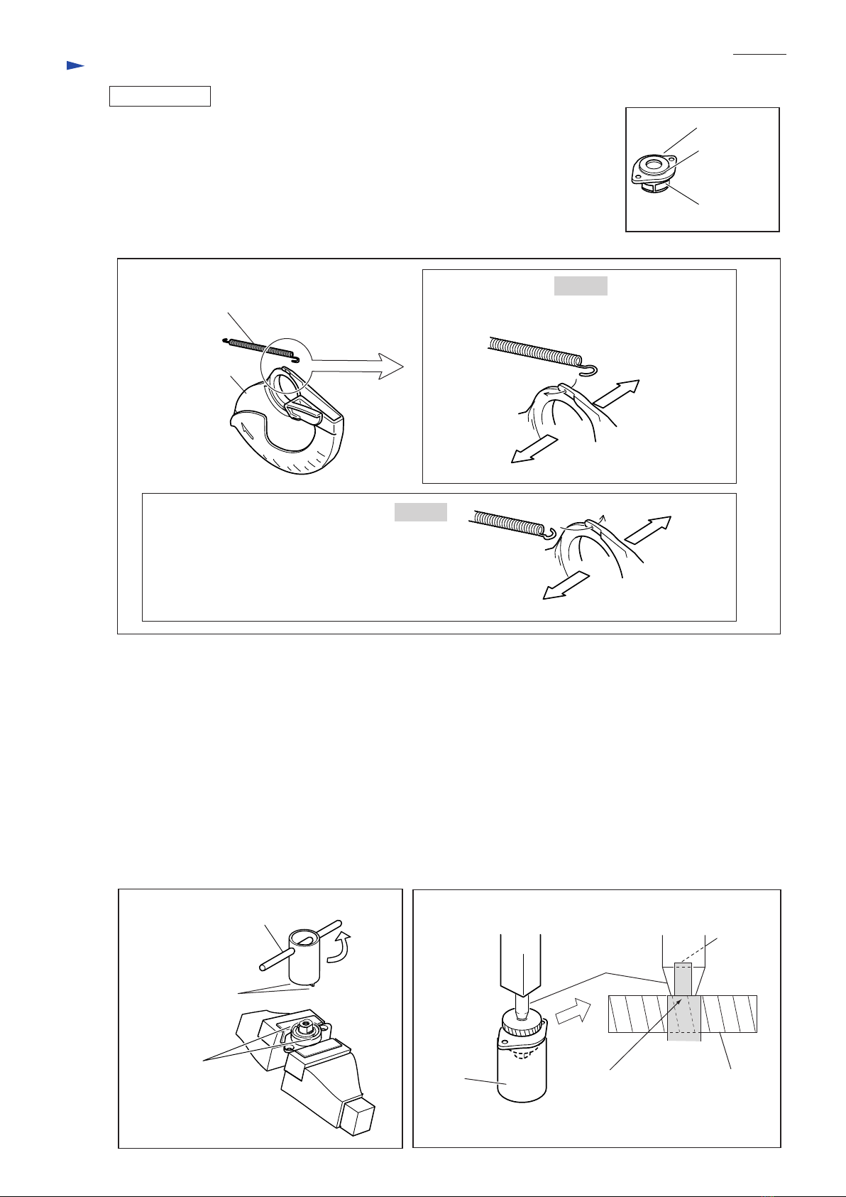
Removing / Mounting retaining ring
Removing helical gear 52
Adjusting the right angle of saw blade to base plate
Holding bearing box, when removing helical gear 52
Bearing extractor
Bearing extractor
Removing / Mounting retaining ring
Adjust the saw blade's angle of 45 degree to base plate
Removing / Mounting bearing retainer
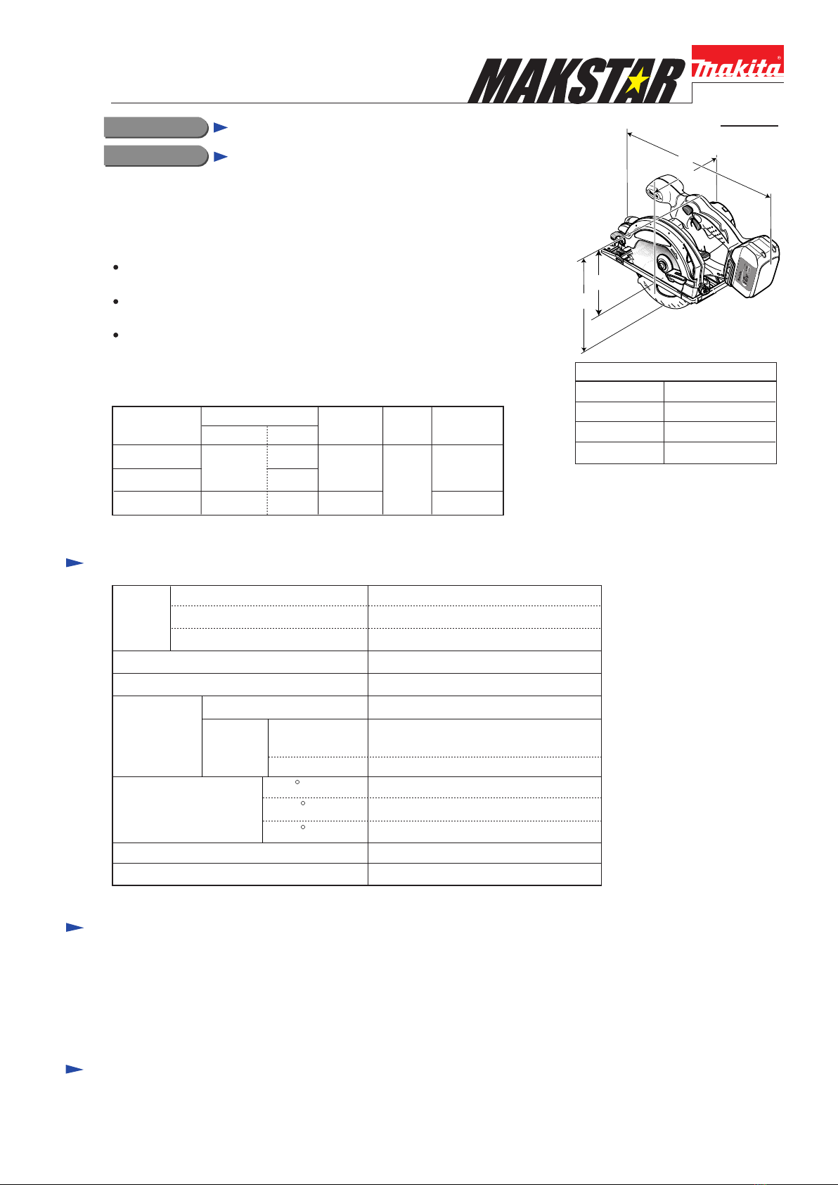
Descriptions Purpose
Item No. Parts item Portion to be lubricated
Helical gear 52
Bearing box
31 Blade case
Amount
Gear room 6g
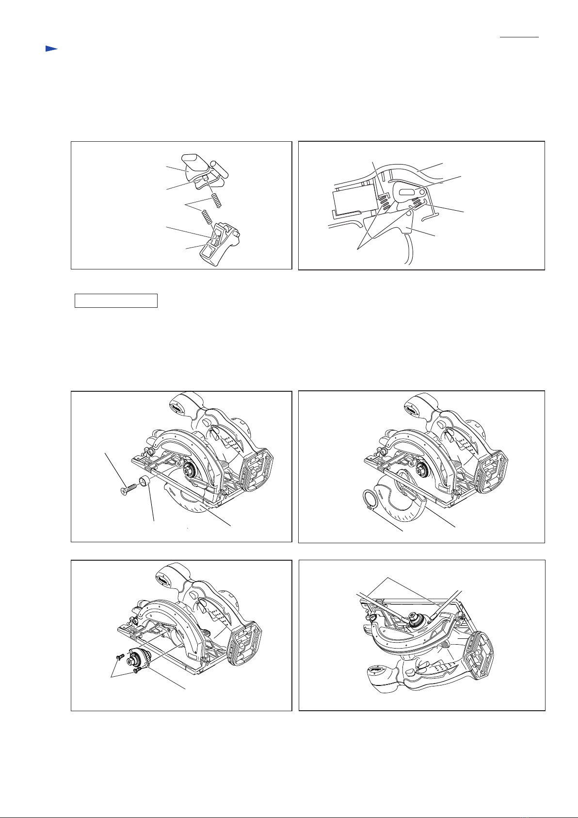
[3] Replacing Base complete
Fig. 2 Fig. 3
1. Loosen M5x6 Hex socket head set screw for fixing Depth guide to Base complete. See Fig.2.
Loosen Lever 40 and remove Shoulder pin 6-7 for connecting Depth guide and Base complete.
2. Remove the following parts as shown in Fig.3. Base complete can be separated from the machine.
A) Shoulder pin 6-7 for connecting Angular guide and Base complete
B) Stop ring E-8, M6 Hex nut, Flat washer 6 and M6x20 Cap square neck bolt for securing Lever 30
3. Reuse the above parts (for example, Mx6 Hex socket head screws) to replace the current base complete by the new one.
Note: M6 Hex nut in Lever 30 is not interchangeable with M6 Hex nut in Lever 40.
The former has left handed threads, the latter has right handed threads.
Stop ring E-8
Shoulder pin 6-7
Cap square
neck bolt M6x20
Hex socket head
set screw M5x6
Lever 30
Flat washer 6
Angular guide
Hex nut M6
Hex wrench
Base complete
Lever 40
Hex. wrench
M5x6 Hex socket set screw Shoulder pin 6-7
CAUTION: Remove Saw blade, Inner flange 40, Outer flange 40, Hex socket head bolt and
Battery cartridge from the machine for safety before repair/ maintenance !