Makita SP6000 User manual

SP6000
0976201
EN Plunge Cut Circular Saw Instruction manual
ZHCN 电动圆锯 使用说明书
ID Gergaji Lingkaran Pemotongan
Petunjuk penggunaan
Benam
VI Maùy Cöa Ñóa Caàm Tay Hoaït Taøi lieäu höôùng daãn
Ñoäng Baèng Ñoäng Cô Ñieän
TH

2
1000114 2000157
3000154 4000156
5000194 6000147
7000029 8007656
21

3
9007669 10 007670
11 007657 12 007659
13 007660 14 007661
15 007671 16 007664
3
3
4
4
5
6
7
8
910
A
B
11
12

4
17 007663 18 007684
19 007662 20 007655
21 007658 22 007672
23 007673 24 007674
13
14
15 11
15
14
16
17
18
19
20
21
22

5
25 007685 26 007666
27 007675 28 007686
29 007678 30 007667
31 007668 32 001145
23
24
25
26
27
B
AA
B
28
29
30

6
33 007676
31
32

7
ENGLISH (Original instructions)
Explanation of general view
SPECIFICATIONS
• Due to our continuing program of research and development, the specifications herein are subject to change ithout
notice.
• Specifications may differ from country to country.
• The eight may differ depending on the attachment(s). The lightest and heaviest combination, according to EPTA-
Procedure 01/2014, are sho n in the table.
Symbols END201-7
The follo ing sho the symbols used for the equipment.
Be sure that you understand their meaning before use.
... Read instruction manual.
............. DOUBLE INSULATION
Intended use ENE067-2
The tool is specially intended for performing plunge cuts.
The tool is also intended for rip and cross cuts in ood. If
the tool is equipped ith proper circular sa blade, the
tool can be used for aluminum board, plastic board, siding
board and metal all panels.
Power supply ENF002-2
The tool should be connected only to a po er supply of
the same voltage as indicated on the nameplate, and can
only be operated on single-phase AC supply. They are
double-insulated and can, therefore, also be used from
sockets ithout earth ire.
General ower tool safety
warnings GEA012-2
WARNING: Read all safety warnings, instructions,
illustrations and specifications pro ided with this
power tool. Failure to follo all instructions listed belo
may result in electric shock, fire and/or serious injury.
Save all warnings and
instructions for future reference.
The term “po er tool” in the arnings refers to your
mains-operated (corded) po er tool or battery-operated
(cordless) po er tool.
Work area safety
1. Keep work area clean and well lit. Cluttered or dark
areas invite accidents.
2. Do not operate power tools in explosi e
atmospheres, such as in the presence of
flammable liquids, gases or dust. Po er tools
create sparks hich may ignite the dust or fumes.
3. Keep children and bystanders away while
operating a power tool. Distractions can cause you
to lose control.
Electrical Safety
1. Power tool plugs must match the outlet. Ne er
modify the plug in any way. Do not use any
adapter plugs with earthed (grounded) power
tools. Unmodified plugs and matching outlets ill
reduce risk of electric shock.
2. A oid body contact with earthed or grounded
surfaces, such as pipes, radiators, ranges and
1. Clamping scre
2. Blade lo er limit stopper
3. Quick stop button
4. Clamping scre s
5. Tool base
6. Positive stopper
7. Lever
8. Bevel angle shifting lever
9. Base
10. Cutting line
11. Lock-off button
12. S itch trigger
13. Speed adjusting dial
14. Hex rench
15. Locking lever
16. Shaft lock
17. Hex bolt
18. Outer flange
19. Sa blade
20. Inner flange
21. Vacuum cleaner
22. Dust port
23. Adjusting scre s
24. Slide lever
25. Rip fence (Guide rule)
26. Rear edge of tool base
27. Fixed stop
28. Adjusting scre for 90°
29. Adjusting scre for 45°
30. Limit mark
31. Scre driver
32. Brush holder cap
Model SP6000
Blade diameter 165 mm
Max. cutting depth
at 90° 56 mm
at 45° 40 mm
at 48° 38 mm
No load speed (min-1) 2,200 - 6,400
Overall length 341 mm
Net eight 4.1 kg
Safety class /II

8
refrigerators. There is an increased risk of electric
shock if your body is earthed or grounded.
3. Do not expose power tools to rain or wet
conditions. Water entering a po er tool ill increase
the risk of electric shock.
4. Do not abuse the cord. Ne er use the cord for
carrying, pulling or unplugging the power tool.
Keep cord away from heat, oil, sharp edges or
mo ing parts. Damaged or entangled cords increase
the risk of electric shock.
5. When operating a power tool outdoors, use an
extension cord suitable for outdoor use. Use of a
cord suitable for outdoor use reduces the risk of
electric shock.
6. If operating a power tool in a damp location is
una oidable, use a residual current de ice (RCD)
protected supply. Use of an RCD reduces the risk of
electric shock.
7. Use of power supply ia an RCD with a rated
residual current of 30 mA or less is always
recommended.
8. Power tools can produce electromagnetic fields
(EMF) that are not harmful to the user. Ho ever,
users of pacemakers and other similar medical
devices should contact the maker of their device and/
or doctor for advice before operating this po er tool.
9. Do not touch the power plug with wet hands.
10. If the cord is damaged, ha e it replaced by the
manufacturer or his agent in order to a oid a
safety hazard.
Personal Safety
1. Stay alert, watch what you are doing and use
common sense when operating a power tool. Do
not use a power tool while you are tired or under
the influence of drugs, alcohol or medication. A
moment of inattention hile operating po er tools
may result in serious personal injury.
2. Use personal protecti e equipment. Always wear
eye protection. Protective equipment such as a dust
mask, non-skid safety shoes, hard hat or hearing
protection used for appropriate conditions ill reduce
personal injuries.
3. Pre ent unintentional starting. Ensure the switch
is in the off-position before connecting to power
source and/or battery pack, picking up or carrying
the tool. Carrying po er tools ith your finger on the
s itch or energising po er tools that have the s itch
on invites accidents.
4. Remo e any adjusting key or wrench before
turning the power tool on. A rench or a key left
attached to a rotating part of the po er tool may result
in personal injury.
5. Do not o erreach. Keep proper footing and
balance at all times. This enables better control of
the po er tool in unexpected situations.
6. Dress properly. Do not wear loose clothing or
jewellery. Keep your hair and clothing away from
mo ing parts. Loose clothes, je ellery or long hair
can be caught in moving parts.
7. If de ices are pro ided for the connection of dust
extraction and collection facilities, ensure these
are connected and properly used. Use of dust
collection can reduce dust-related hazards.
8. Do not let familiarity gained from frequent use of
tools allow you to become complacent and ignore
tool safety principles. A careless action can cause
severe injury ithin a fraction of a second.
9. Always wear protecti e goggles to protect your
eyes from injury when using power tools. The
goggles must comply with ANSI Z87.1 in the USA,
EN 166 in Europe, or AS/NZS 1336 in Australia/
New Zealand. In Australia/New Zealand, it is
legally required to wear a face shield to protect
your face, too. (Fig. 1)
It is an employer’s responsibility to enforce the
use of appropriate safety protecti e equipments
by the tool operators and by other persons in the
immediate working area.
Power tool use and care
1. Do not force the power tool. Use the correct power
tool for your application. The correct po er tool ill
do the job better and safer at the rate for hich it as
designed.
2. Do not use the power tool if the switch does not
turn it on and off. Any po er tool that cannot be
controlled ith the s itch is dangerous and must be
repaired.
3. Disconnect the plug from the power source and/or
remo e the battery pack, if detachable, from the
power tool before making any adjustments,
changing accessories, or storing power tools.
Such preventive safety measures reduce the risk of
starting the po er tool accidentally.
4. Store idle power tools out of the reach of children
and do not allow persons unfamiliar with the
power tool or these instructions to operate the
power tool. Po er tools are dangerous in the hands
of untrained users.
5. Maintain power tools and accessories. Check for
misalignment or binding of mo ing parts,
breakage of parts and any other condition that
may affect the power tool’s operation. If damaged,
ha e the power tool repaired before use. Many
accidents are caused by poorly maintained po er
tools.
6. Keep cutting tools sharp and clean. Properly
maintained cutting tools ith sharp cutting edges are
less likely to bind and are easier to control.
7. Use the power tool, accessories and tool bits etc.
in accordance with these instructions, taking into
account the working conditions and the work to
be performed. Use of the po er tool for operations
different from those intended could result in a
hazardous situation.
8. Keep handles and grasping surfaces dry, clean
and free from oil and grease. Slippery handles and
grasping surfaces do not allo for safe handling and
control of the tool in unexpected situations.
9. When using the tool, do not wear cloth work
glo es which may be entangled. The entanglement
of cloth ork gloves in the moving parts may result in
personal injury.
Ser ice
1. Ha e your power tool ser iced by a qualified
repair person using only identical replacement

9
parts. This ill ensure that the safety of the po er tool
is maintained.
2. Follow instruction for lubricating and changing
accessories.
CIRCULAR SAW SAFETY
WARNINGS GEB144-3
Cutting procedures
1. DANGER: Keep hands away from cutting area
and the blade. Keep your second hand on
auxiliary handle, or motor housing. If both hands
are holding the sa , they cannot be cut by the blade.
2. Do not reach underneath the workpiece. The guard
cannot protect you from the blade belo the
orkpiece.
3. Adjust the cutting depth to the thickness of the
workpiece. Less than a full tooth of the blade teeth
should be visible belo the orkpiece.
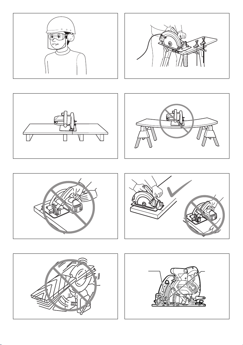
4. Ne er hold the workpiece in your hands or across
your leg while cutting. Secure the workpiece to a
stable platform. It is important to support the ork
properly to minimise body exposure, blade binding, or
loss of control. (Fig. 2)
5. Hold the power tool by insulated gripping
surfaces, when performing an operation where the
cutting tool may contact hidden wiring or its own
cord. Contact ith a “live” ire ill also make exposed
metal parts of the po er tool “live” and could give the
operator an electric shock.
6. When ripping, always use a rip fence or straight
edge guide. This improves the accuracy of cut and
reduces the chance of blade binding.
7. Always use blades with correct size and shape
(diamond ersus round) of arbour holes. Blades
that do not match the mounting hard are of the sa
ill run off-centre, causing loss of control.
8. Ne er use damaged or incorrect blade washers or
bolt. The blade ashers and bolt ere specially
designed for your sa , for optimum performance and
safety of operation.
Kickback causes and related warnings
- kickback is a sudden reaction to a pinched, jammed or
misaligned sa blade, causing an uncontrolled sa to
lift up and out of the orkpiece to ard the operator;
- hen the blade is pinched or jammed tightly by the kerf
closing do n, the blade stalls and the motor reaction
drives the unit rapidly back to ard the operator;
- if the blade becomes t isted or misaligned in the cut,
the teeth at the back edge of the blade can dig into the
top surface of the ood causing the blade to climb out
of the kerf and jump back to ard the operator.
Kickback is the result of sa misuse and/or incorrect
operating procedures or conditions and can be avoided by
taking proper precautions as given belo .
1. Maintain a firm grip with both hands on the saw
and position your arms to resist kickback forces.
Position your body to either side of the blade, but
not in line with the blade. Kickback could cause the
sa to jump back ards, but kickback forces can be
controlled by the operator, if proper precautions are
taken.
2. When blade is binding, or when interrupting a cut
for any reason, release the trigger and hold the
saw motionless in the material until the blade
comes to a complete stop. Ne er attempt to
remo e the saw from the work or pull the saw
backward while the blade is in motion or kickback
may occur. Investigate and take corrective actions to
eliminate the cause of blade binding.
3. When restarting a saw in the workpiece, centre the
saw blade in the kerf so that the saw teeth are not
engaged into the material. If a sa blade binds, it
may alk up or kickback from the orkpiece as the
sa is restarted.
4. Support large panels to minimise the risk of blade
pinching and kickback. Large panels tend to sag
under their o n eight. Supports must be placed
under the panel on both sides, near the line of cut and
near the edge of the panel. (Fig. 3 & 4)
5. Do not use dull or damaged blades.
Unsharpened or improperly set blades produce
narro kerf causing excessive friction, blade binding
and kickback.
6. Blade depth and be el adjusting locking le ers
must be tight and secure before making the cut. If
blade adjustment shifts hile cutting, it may cause
binding and kickback.
7. Use extra caution when sawing into existing walls
or other blind areas. The protruding blade may cut
objects that can cause kickback.
8. ALWAYS hold the tool firmly with both hands.
NEVER place your hand, leg or any part of your
body under the tool base or behind the saw,
especially when making cross-cuts. If kickback
occurs, the sa could easily jump back ards over
your hand, leading to serious personal injury. (Fig. 5)
9. Ne er force the saw. Push the saw forward at a
speed so that the blade cuts without slowing.
Forcing the sa can cause uneven cuts, loss of
accuracy, and possible kickback.
Guard function
1. Check the guard for proper closing before each
use. Do not operate the saw if the guard does not
mo e freely and enclose the blade instantly. Ne er
clamp or tie the guard so that the blade is
exposed. If the sa is accidentally dropped, the guard
may be bent. Check to make sure that guard moves
freely and does not touch the blade or any other part,
in all angles and depths of cut.
2. Check the operation and condition of the guard
return spring. If the guard and the spring are not
operating properly, they must be ser iced before
use. The guard may operate sluggishly due to
damaged parts, gummy deposits, or a build-up of
debris.
3. Assure that the base plate of the saw will not shift
while performing a “plunge cut”. Blade shifting
side ays ill cause binding and likely kick back.
4. Always obser e that the guard is co ering the
blade before placing the saw down on bench or
floor. An unprotected, coasting blade ill cause the
sa to alk back ards, cutting hatever is in its path.
Be a are of the time it takes for the blade to stop after
s itch is released.
Additional safety warnings
1. Use extra caution when cutting damp wood,
pressure treated lumber, or wood containing

10
knots. Maintain smooth advancement of tool ithout
decrease in blade speed to avoid overheating the
blade tips and if cutting plastics, to avoid melting the
plastic.
2. Do not attempt to remo e cut material when blade
is mo ing. Wait until blade stops before grasping
cut material. Blades coast after turn off.
3. A oid cutting nails. Inspect for and remo e all
nails from lumber before cutting.
4. Place the wider portion of the saw base on that
part of the workpiece which is solidly supported,
not on the section that will fall off when the cut is
made. If the workpiece is short or small, clamp it
down. DO NOT TRY TO HOLD SHORT PIECES BY
HAND! (Fig. 6)
5. Before setting the tool down after completing a
cut, be sure that the guard has closed and the
blade has come to a complete stop.
6. Ne er attempt to saw with the circular saw held
upside down in a ise. This is extremely
dangerous and can lead to serious accidents.
(Fig. 7)
7. Some material contains chemicals which may be
toxic. Take caution to pre ent dust inhalation and
skin contact. Follow material supplier safety data.
8. Do not stop the blades by lateral pressure on the
saw blade.
9. Do not use any abrasi e wheels.
10. Only use the saw blade with the diameter that is
marked on the tool or specified in the manual. Use
of an incorrectly sized blade may affect the proper
guarding of the blade or guard operation hich could
result in serious personal injury.
11. Keep blade sharp and clean. Gum and ood pitch
hardened on blades slo s sa and increases
potential for kickback. Keep blade clean by first
removing it from tool, then cleaning it ith gum and
pitch remover, hot ater or kerosene. Never use
gasoline.
12. Wear a dust mask and hearing protection when
use the tool.
13. Always use the saw blade intended for cutting the
material that you are going to cut.
14. Only use the saw blades that are marked with a
speed equal or higher than the speed marked on
the tool.
15. (For European countries only)
Always use the blade which conforms to EN847-1.
SAVE THESE INSTRUCTIONS.
WARNING: DO NOT let comfort or familiarity with
product (gained from repeated use) replace strict
adherence to safety rules for the subject product.
MISUSE or failure to follow the safety rules stated in
this instruction manual may cause serious personal
injury.
FUNCTIONAL DESCRIPTION
CAUTION:
• Al ays be sure that the tool is s itched off and
unplugged before adjusting or checking function on the
tool.
Adjusting depth of cut (Fig 8)
CAUTION:
• After adjusting the depth of cut, al ays tighten the
clamping scre securely.
Loosen the clamping scre on the depth guide and move
the blade lo er limit stopper to the desired depth on the
scale plate. At the desired depth of cut, tighten the
clamping scre firmly.
For cleaner, safer cuts, set cut depth so that no more than
one blade tooth projects belo orkpiece. Using proper
cut depth helps to reduce potential for dangerous
KICKBACKS hich can cause personal injury.
NOTE:
• Setting the blade lo er limit stopper to the desired
depth on the scale plate allo s rough depth of cut. For
accurate depth of cut, measure the actual protrusion of
sa blade belo the tool base.
Quick stop button for 2 to 3 mm depth of
cut when using guide rail (accessory)
(Fig 9)
This tool has the quick stop button for 2 to 3 mm depth of
cut on the gear housing aside the rear handle hen using
guide rail. This is used hen avoiding splinter on the
orkpiece in the cut. Make a pass of the 2 to 3 mm first
cut and then make another pass of usual cut.
To obtain the 2 to 3 mm depth of cut, push in the stop
button to ard the sa blade. This is convenient for
avoiding splinter on the orkpiece.
To release the depth of cut from this position for free depth
of cut, just pull the button back. (Fig. 10)
Bevel cutting (Fig 11)
Tilting to the right (Fig. 12)
Turn the positive stopper so that the arro on it points one
of t o positions (vertical for 22.5°, horizontal for 45°).
Loosen the clamping scre s in front and back. Then, tilt
the tool base until it stops and secure the base ith the
clamping scre s.
To get 48° bevel angle, move the lever to 48° marking as
far as it ill go. Turn the positive stopper so that the arro
on it points to the horizontal position. Then, tilt the tool
base until it stops and secure the base ith the clamping
scre s. (Fig. 13)
Tilting to the left (Fig. 14)
The tool can be tilted to the left 1° bevel angle. To get the
left 1° bevel angle, loosen the clamping scre s in front
and back, tilt the tool handle slightly to the right and push
t o bevel angle shifting levers at the same time in the
direction of arro hich has a marking -1. And then tilt the
tool handle to the left hile pushing these t o levers at
the same time. Secure the base ith the clamping scre s.
NOTE:
• Returning the blade to the right angle makes the
shifting lever return to 0° by itself.

11
Sighting (Fig 15)
When using the tool without guide rail (accessory)
For straight cuts, align the A position on the front of the
base ith your cutting line. For 45° bevel cuts, align the B
position ith it.
When using the tool with guide rail (accessory)
For both straight cuts and 45° bevel cuts, al ays align the
A position on the front of the base ith your cutting line.
Switch action (Fig 16)
CAUTION:
• Before plugging in the tool, al ays check to see that
the s itch trigger actuates properly and returns to the
“OFF” position hen released.
To prevent the s itch trigger from being accidentally
pulled, a lock-off button is provided. To start the tool, push
in the lock-off button and pull the s itch trigger. Release
the s itch trigger to stop.
Speed adjusting dial (Fig 17)
The tool speed can be adjusted by turning the adjusting
dial. Higher speed is obtained hen the dial is turned in
the direction of number 6; lo er speed is obtained hen it
is turned in the direction of number 1.
Refer to the table to select the proper speed for the
orkpiece to be cut. Ho ever, the appropriate speed may
differ ith the type or thickness of the orkpiece. In
general, higher speeds ill allo you to cut orkpieces
faster but the service life of the blade ill be reduced.
015770
CAUTION:
• The speed adjusting dial can be turned only as far as 6
and back to 1. Do not force it past 6 or 1, or the speed
adjusting function may no longer ork.
• The speed adjusting dial is not for using lo speed
rated sa blades but for obtaining a speed hich is
suitable to material of orkpiece. Use only sa blades
hich are rated for at least the maximum no load
speed stated in the SPECIFICATIONS.
The tools equipped ith electronic function are easy to
operate because of the follo ing features.
O erload protector
When the tool is overloaded and current flo s above a
certain level, the tool automatically stops to protect motor.
Constant speed control
Electronic speed control for obtaining constant speed.
Possible to get fine finish, because the rotating speed is
kept constant even under load condition.
Soft start feature
Soft start because of suppressed starting shock.
ASSEMBLY
CAUTION:
• Al ays be sure that the tool is s itched off and
unplugged before carrying out any ork on the tool.
Hex wrench storage (Fig 18)
Hex rench is stored on the tool. To remove hex rench,
just pull it out.
To install hex rench, place it on the grip and insert it as
far as it ill go.
Removing or installing saw blade
CAUTION:
• Do not use sa blades hich do not comply ith the
characteristics specified in these instructions.
• Use only sa blades hich are rated for at least the
maximum no load speed stated in the
SPECIFICATIONS.
• Be sure the blade is installed ith teeth pointing up at
the front of the tool.
• Use only the Makita rench to install or remove the
blade.
To remove the blade, push in the lock-off button to unlock
the upper limit stopper. (Fig. 19)
Turn the locking lever to lock the sa head for replacing a
blade. (Fig. 20)
With the lock-off button depressed and the locking lever
turned, lo er the handle so that the lock pin fits in the
groove formed by the locking lever and the depth guide
ith scale plate. Make sure that the lock pin fits in the
groove.
Press the shaft lock fully so that the blade cannot revolve
and use the rench to loosen the hex bolt
counterclock ise. Then remove the hex bolt, outer flange
and blade. (Fig. 21)
To install the blade, follo the removal procedure in
reverse. BE SURE TO TIGHTEN THE HEX BOLT
CLOCKWISE SECURELY. (Fig. 22)
Blade guard cleaning
When changing the circular sa blade, make sure to also
clean the blade guard of accumulated sa dust as
discussed in the Maintenance section. Such efforts do not
replace the need to check guard operation before each
use.
Connecting a vacuum cleaner (Fig 23)
When you ish to perform clean cutting operation,
connect a Makita vacuum cleaner to your tool. Connect a
hose of the vacuum cleaner to the dust port as sho n in
the figure.
OPERATION
Section cutting (ordinary sawing)
CAUTION:
• Be sure to move the tool for ard in a straight line
gently. Forcing or t isting the tool ill result in
Number min-1
12,200
22,700
33,800
44,900
56,000
66,400

12
overheating the motor and dangerous kickback,
possibly causing severe injury.
• Never approach any part of your body under the tool
base hen section cutting, especially at starting. Doing
so may cause serious personal injuries. The blade is
exposed under the tool base.
Hold the tool firmly. The tool is provided ith both a front
grip and rear handle. Use both to best grasp the tool. If
both hands are holding sa , they cannot be cut by the
blade. Set the front of base on the orkpiece to be cut
ithout the blade making any contact. Then push in the
lock-off button and turn the tool on and ait until the blade
attains full speed. No press do n the sa head slo ly to
the preset depth of cut and simply move the tool for ard
over the orkpiece surface, keeping it flat and advancing
smoothly until the sa ing is completed.
To get clean cuts, keep your sa ing line straight and your
speed of advance uniform. If the cut fails to properly follo
your intended cut line, do not attempt to turn or force the
tool back to the cut line. Doing so may bind the blade and
lead to dangerous kickback and possible serious injury.
Release s itch, ait for blade to stop and then ithdra
tool. Realign tool on ne cut line, and start cut again.
Attempt to avoid positioning hich exposes operator to
chips and dust being ejected from sa . Use eye
protection to help avoid injury. (Fig. 24)
When using with guide rail (accessory)
(Fig 25)
Place the tool on the rear end of guide rail. Turn t o
adjusting scre s on the tool base so that the tool slides
smoothly ithout a clatter. Hold the tool firmly. The tool is
provided ith both a front grip and rear handle. Use both
to best grasp the tool. Turn on the tool, press do n the
tool to the preset depth of cut and cut the splinterguard
along the full length ith a stroke. The edge of the
splinterguard corresponds to the cutting edge.
When bevel cutting ith the guide rail, slide the slide lever
on the tool base so that the tool does not fall do n on its
side. (Fig. 26)
Move the slide lever on the tool base in the direction of
arro so that it engages the undercut groove in the guide
rail.
Rip fence (guide rule) (Optional
accessory) (Fig 27)
The handy rip fence allo s you to do extra-accurate
straight cuts. Simply slide the rip fence up snugly against
the side of the orkpiece and secure it in position ith the
scre s on the front and the back of the base. It also
makes repeated cuts of uniform idth possible.
Overturning the rip fence (guide rule) also orks as a sub
base for the tool.
Plunge cutting (Cutting-out) (Fig 28)
WARNING:
• To avoid a kickback, be sure to observe the follo ing
instructions.
When using the tool without guide rail
Place the tool on the orkpiece ith the rear edge of tool
base against a fixed stop or equivalent hich is devised
by an operator.
When using the tool with guide rail
Place the tool on the guide rail ith the rear edge of tool
base against a fixed stop or equivalent hich is clamped
on the guide rail.
Hold the tool firmly ith one hand on the front grip and the
other on the tool handle. Then push in the lock-off button
and turn the tool on and ait until the blade attains full
speed. No press do n the sa head slo ly to the preset
depth of cut and simply move the tool for ard to the
desired plunge position.
NOTE:
• The markings on the side of the blade guard sho the
front and rear cutting points of the sa blade (A for
diameter 160 mm and B for diame-ter 165 mm) at the
maximum cutting depth and using the guide rail.
(Fig. 29)
Guide device (accessories)
Use of the miter gauge (accessory) allo s exact miter
cuts ith angles and fitting orks.
Use of the clamp (accessory) ensures firm hold of
orkpiece on the table.
MAINTENANCE
CAUTION:
• Al ays be sure that the tool is s itched off and
unplugged before attempting to perform inspection or
maintenance.
•Clean out the guard to ensure there is no
accumulated sawdust which may impede the
operation of the guarding system. A dirty guarding
system may limit the proper operation hich could
result in serious personal injury. The most effective
ay to accomplish this cleaning is ith compressed air.
If the dust is being blown out of the guard, be sure
the proper eye and breathing protection is used.
• Never use gasoline, benzine, thinner, alcohol or the
like. Discoloration, deformation or cracks may result.
Adjusting for accuracy of 90° and 45° cut
(vertical and 45° cut)
This adjustment has been made at the factory. But if it is
off, adjust the adjusting scre s ith a hex rench hile
inspecting 90° or 45° the blade ith the base using a
triangular rule or square rule, etc. (Fig. 30 & 31)
NOTE:
• Adjusting for accuracy of 22.5°, 48° and -1° cut cannot
be performed.
Replacing carbon brushes (Fig 32)
Remove and check the carbon brushes regularly. Replace
hen they ear do n to the limit mark. Keep the carbon
brushes clean and free to slip in the holders. Both carbon
brushes should be replaced at the same time. Use only
identical carbon brushes. (Fig. 33)
Use a scre driver to remove the brush holder caps. Take
out the orn carbon brushes, insert the ne ones and
secure the brush holder caps.
To maintain product SAFETY and RELIABILITY, repairs,
any other maintenance or adjustment should be

13
performed by Makita Authorized Service Centers, al ays
using Makita replacement parts.
OPTIONAL ACCESSORIES
CAUTION:
• These accessories or attachments are recommended
for use ith your Makita tool specified in this manual.
The use of any other accessories or attachments might
present a risk of injury to persons. Only use accessory
or attachment for its stated purpose.
If you need any assistance for more details regarding
these accessories, ask your local Makita Service Center.
• Sa blades
• Guide rail
• Rip fence (Guide rule)
• Miter gauge
• Clamp
• Hex rench
• Sheet set for guide rail
• Rubber sheet set for guide rail
• Position sheet set for guide rail
NOTE:
• Some items in the list may be included in the tool
package as standard accessories. They may differ from
country to country.

14
简体中文 (原厂指导手册)
总图说明
规格
•鉴于我司将持续实施研发计划,此处规格如有变更,恕不另行通知。
•本 品在各个国家的规格可能有所不同。
•视附件的情况,重量可能不同。最轻和最重的组合 (根据 EPTA-Procedure 01/2014)显示
在表中。
符号 END201-7
下列所示为用于设备的符号。请确保在使用
前理解各个符号的含义。
... 请阅读操作手册。
........ 双重绝缘
设计用途 ENE067-2
本工具专门设计用于切入式切割。该工具还
适用于木材裁板和十字切割。如果工具配有
合适的圆锯刀片,该工具可用于铝板、塑料
板、壁板和金属墙板。
电源 ENF002-2
本工具只能连接铭牌上所示的电源,只能在
单相交流电源下作业。此类工具为双重绝缘,
因此也可以从未接地线的插座使用本工具。
电动工具一般安全警告
GEA012-2
警告:阅读此电动工具提供的所有安全警
告、说明、插图和 格。违反以下列出的任
何指示可能导致触电、火灾和 / 或严重的人
身伤害事故。
1. 夹紧螺钉
2. 刀片下部限位止动器
3. 快停按钮
4. 夹紧螺钉
5. 工具底座
6. 正止动器
7. 杆
8. 斜角转换杆
9. 底座
10. 切割线
11. 锁定关按钮
12. 开关扳机
13. 速度调节转盘
14. 六角扳手
15. 锁杆
16. 轴锁
17. 六角螺栓
18. 外法兰
19. 锯刀片
20. 内法兰
21. 集尘器
22. 灰尘口
23. 调节螺钉
24. 滑杆
25. 锯栅 (导规)
26. 工具底座后缘
27. 固定挡块
28. 90°调节螺钉
29. 45°调节螺钉
30. 限位标记
31. 螺丝刀
32. 碳刷固定器盖
型号 SP6000
刀片直径 165 mm
最大切割深度
90°56 mm
45°40 mm
48°38 mm
空载速度 (/min) 2,200 - 6,400
总长 341 mm
净重 4.1 kg
安全等级 /II

15
请妥善保存所有的警告和操
作指示以备日后参考。
在该警告中的 “电动工具 ”是指电网电源
供电 (接电源线)的电动工具或电池驱动
(充电式)电动工具。
工作区域安全
1. 保持工作区域干净,照明良好。杂乱或
黑暗的工作场所容易引发事故。
2. 不得在有爆炸性危险的环境 (如存在易
燃液体、气体和粉尘)中使用电动工具。
操作电动工具时会 生火花,而这可能
引燃粉尘或烟 。
3. 操作电动工具时,请让儿童和旁观者远
离工作区域。注意力分散可能导致操作
失控。
电气安全
1. 电动工具的插头必须与插座相匹配。切
勿以任何方式对插头进行改装。转接插
头不得和接了地线的电动工具一起使用。
未经改动的插头和相匹配的插座有利于
减少电击危险。
2. 避免身体与接地的物体接触,如水管、
散热器、电炉和电冰箱等。如果您的身
体接地了,会增加电击的危险。
3. 不得将电动工具暴露在雨中或湿的环境
中。如果有水进入电动工具将增加电击
的危险。
4. 请勿不当使用电线。切勿用导线拖携工
具或拔下电动工具的插头。将电线保存
在远离高温、油垢、锐边或移动部件之
处。损坏或缠绕的电线会增加电击危险。
5. 当在户外操作电动工具时,只能使用合
适的户外专用延长电线。使用合适的户
外专用电线将减少电击危险。
6. 如果不能避免在潮湿的环境中使用电动
工具,请使用受剩余电流装置 (RCD)保
护的电源。使用 RCD 可减少电击危险。
7. 建议务必使用 RCD 的额定剩余电流为
30 mA 或更小的电源。
8. 电动工具可产生对用户无害的电磁场
(EMF)。然而,心脏起搏器和其他类似
医疗设备的用户应该在操作该电动工具
前,应联系其设备的制造商和/或医生
以获得建议。
9. 请勿用湿手触碰电源插头。
10. 如果电源线损坏,请由制造商或其代理
进行更换,避免安全危险。
人身安全
1. 操作电动工具时请保持警惕,注意您的
操作并运用常识。疲惫、饮酒或服用毒
品、药物之后,切勿操作电动工具。使
用电动工具时只要稍微分心便可能导致
严重的人身伤害事故。
2. 请使用个人劳防用品。总是佩戴护目镜。
根据使用情况穿戴合适的防护装备,例
如防尘面罩、止滑工作鞋、安全帽或耳
罩,可降低人身伤害事故发生的几率。
3. 防止意外启动。在连接电源和 / 或电池
组、拿起或搬运工具之前,请确保开关
处于关闭位置。如果在提携电动工具时,
您的手指触碰了开关,或连接电源时,
开关仍然处于启动位置,都可能引发意
外事故。
4. 电动工具开机前,除去任何调节工具或
扳手。电动工具的旋转部件上如果还插
有扳手或调节工具可能会导致人身伤害。
5. 避免错误的持机姿势。务必站稳并始终
保持平衡。正确的操作姿势能够帮助您
在突发状况下及时控制住电动工具。
6. 合理着装。请勿穿戴宽松的衣服或佩戴
首饰。保持头发和衣服远离移动机件。
宽松的衣服、首饰或长头发可能会被卡
入移动机件中。
7. 如果设备能连接除尘或集尘装置,确保
这些装置已经连接并被正确使用。使用
集尘装置可减少尘屑相关的危害。
8. 不要让经常使用工具而获得的熟悉让您
变得自满并忽视工具安全原则。粗心的
动作可能在几分之一秒内造成严重伤害。
9. 使用电动工具时,请始终佩戴护目镜以
保护眼 免受伤害。护目镜必须符合美
国 ANSI Z87.1、欧洲 EN 166 或澳大利
亚/新西兰 AS/NZS 1336 标准。在澳大
利亚 /新西兰,法律要求佩戴面罩以保
护您的面部。(图 1)
雇主有责任强制工具操作员和附近工作
区域的其他人员使用适当的安全防护设
备。

16
电动工具使用和保养
1. 不要滥用电动工具。根据应用情况选择
适合的电动工具。正确地选用电动工具
可以在规定的功率范围中,更有效率更
安全的操作机器。
2. 不要使用开关故障的电动工具。如果无
法正常操控起停开关,极容易在操作机
器时生意外,必须进行修理。
3. 在调整机器设置、更换配件或存放电动
工具前,必须先断开插头与电源的连接
和/或从电动工具中取出电池组 (如果
可拆卸)。 这些预防性的安全措施能减少
意外启动电动工具的危险。
4. 将不用的电动工具保存在儿童接触不到
的地方。禁止不熟悉电动工具或这些操
作说明的人员使用电动工具。未经训练
的人员操作电动工具是危险的行为。
5. 维护电动工具和配件。检查运动部件是
否有偏差或粘连,部件是否破损,以及
其它可能会影响工具运行的情况。如有
损坏,使用前需修理完毕。很多事故都
是由于没有对电动工具进行很好维护造
成的。
6. 切割工具必须保持锋利和清洁。经过细
心保养且刀刃锋利的切割工具不易被夹
住,并较容易操作。
7. 使用电动工具、配件和刀头等时应考虑
工作条件和要进行工作的性质,遵循相
应的操作指示。将电动工具用于既定用
途以外的目的时,可能会导致危险。
8. 保持手柄和抓握表面干燥、清洁、无油
脂。意外情况下,光滑的手柄和抓握表
面无法安全操作和控制工具。
9. 使用工具时,请勿穿戴可能缠绕的布工
作手套。布工作手套在活动部件中缠结
可能导致人身伤害。
维修
1. 电动工具只能由有相关资质的维修人员
进行修理,修理时只能使用原厂零配件。
唯有如此才能确保电动工具的安全性。
2. 按照要求对配件进行润滑和更换。
圆锯安全警告 GEB144-3
切割步骤
1. 危险:将手远离切割区域和刀片。将
另外一只手放在辅助手柄或电机外壳上。
如果双手握住锯子,则刀片不能切割它
们。
2. 不要在工件下方。防护装置无法保护您
免受工件下方刀片的伤害。
3. 将切削深度调整为工件厚度。在工件下
方应能看到不完整的刀齿。
4. 切割时切勿将工件握在手上或跨过腿部。
将工件固定在稳定的平台上。重要的是
要能良好的支撑,尽量减少身体暴露、
刀片粘合或失去控制。(图 2)
5. 在切割工具可能接触隐藏线路或其自身
线缆的地方进行操作时,通过绝缘的夹
持表面固定电动工具。接触 “带电”
的电线也将使电动工具暴露的金属部件
“带电”,并且可能给操作者造成电
击。
6. 锯切时,请始终使用锯栅或直边导板。
这提高了切割的准确性并降低刀片粘合
的可能性。
7. 始终使用有正确的心轴孔尺寸和形状
(菱形与圆形)的刀片。与锯子安装硬件
不匹配的刀片将偏离中心,导致失控。
8. 切勿使用损坏或不正确的刀片垫圈或螺
栓。刀片垫圈和螺栓是专门为您的锯子
设计,以获得最佳性能和操作安全性。
反冲和相关警告
-反冲是针对夹紧、卡住或未对准锯刀片的
突然反应,导致失控的锯子抬起并 开工
件朝向操作员;
- 当刀片由于切口闭合被夹紧或卡住时,刀
片停转并且电机的反作用使设备迅速回向
操作员;
- 如果刀片在切口中扭曲或未对准,刀片后
缘处的齿可能会钻入木材的顶部表面,导
致刀片从切口中爬出并向操作员跳回。
反冲是锯子误操作和 / 或不正确的操作程序
或条件的结果,可以通过采取以下列出的适
当预防措施来避免。
1. 用双手牢牢握住锯子,让手臂处于能抵
抗反冲力的位置。让身体处于刀片的两
侧,但不要与刀片对齐。反冲可能导致

17
锯子向后跳,但如果采取适当的预防措
施,操作员可以控制反冲力。
2. 当刀片粘合或由于任何原因中断切割时,
松开扳机并保持锯子在材料中无动作,
直到刀片完全停止。在刀片运动或可能
发生反冲时,切勿尝试从工作中取出锯
子或向后拉锯子。调查并采取纠正措施,
消除刀片粘合的原因。
3. 当重新启动工件中的锯子时,将锯刀片
置于切口中心,使锯齿不会咬合到材料
中。如果锯刀片粘合,当锯子重新启动
时,它可能会从工件上移动或反冲。
4. 支持大面板,最大限度地降低刀片挤压
和反冲风险。大面板倾向于依靠自重下
垂。支架必须放置在面板两侧,靠近切
割线和面板边缘。(图 3 和 4)
5. 不要使用钝的或损坏的刀片。
不锋利或不正确设置的刀片会生狭窄
的切口,导致过度摩擦、刀片粘合和反
冲。
6. 在进行切割之前,刀片深度和斜角调节
锁定杆必须紧固。如果在切割时刀片调
节发生变化,则可能导致粘合和反冲。
7. 锯入现有墙壁或其他盲区时要格外小心。
突出的刀片可能会切割导致反冲的物体。
8. 务必要用双手握紧工具。切勿将手、腿
或身体的任何部位放在工具底座下或锯
子后面,特别是在进行横切时。如果发
生反冲,锯子很容易向后跳过你的手,
导致严重的人身伤害。(图 5)
9. 切勿强行用锯子。以一定的速度向前推
锯子,使刀片不会减速。强行用锯子可
能导致切割不均匀、精度下降并有反冲
可能。
护罩功能
1. 每次使用前检查护罩是否正确关闭。如
果护罩不能自由移动请勿操作锯子并立
即关闭刀片。切勿夹紧或系紧护罩,以
免刀片暴露在外。如果锯子意外掉落,
护罩可能会弯曲。检查以确保在所有切
割角度和深度下,护罩能自由移动并且
不会接触刀片或任何其他部件。
2. 检查护罩回转弹簧的运行和状况。如果
护罩和弹簧不能正常工作,则必须在使
用前进行维修。由于部件损坏、粘性沉
积物或碎屑堆积,护罩可能运行缓慢。
3. 确保执行“切入式切割”时,电圆锯的
基板不会移位。锯片侧向移位会导致锯
片卡滞和反弹。
4. 在将锯子放在工作台或地板上之前,务
必注意护罩是否盖住刀片。未受保护的
滑行刀片将使锯子向后移动,切割其路
径上的任何物体。请注意释放开关后刀
片停止所需的时间。
其他安全警告
1. 切割潮湿的木材、加压处理过的木材或
含有木结的木材时要格外小心。在不降
低刀片速度的情况下保持工具的平稳前
进,避免刀片尖端过热。如果切割塑料,
避免融化塑料。
2. 刀片移动时,请勿尝试移除切割材料。
等到刀片停止后,抓住切割材料。关闭
后刀片还会滑行。
3. 避免切割到钉子。切割前检查并清除木
材上的所有钉子。
4. 将锯子底座的较宽部分放置在牢固支撑
的工件部分上,而不是放在切割时会脱
落的部分上。如果工件短小,请将其夹
紧。不要试图用手握住短件!(图 6)
5. 完成切割后放下工具之前,请确保护罩
已关闭且刀片已完全停止。
6. 切勿尝试将圆锯倒置在虎钳中。这非常
危险,可能导致严重事故。( 图7)
7. 某些材料含有可能有毒的化学物质。请
避免吸入粉尘或使其接触到皮肤。请遵
循材料供应商的安全要求。
8. 不要通过刀片上的侧向压力来停止刀片。
9. 不要使用任何砂轮。
10. 只能使用工具上标有直径或手册中指定
直径的锯刀片。使用尺寸不正确的刀片
可能会影响刀片的正确防护或防护操作,
从而导致严重的人身伤害。
11.保持刀片锋利清洁。刀片上的树胶和木
青变硬会减慢刀片的速度,增加反冲
的可能性。首先将刀片从工具中取出,
然后用树胶和青去除剂、热水或煤油
进行清洁,保持刀片清洁。切勿使用汽
油。

18
12. 使用工具时,请佩戴防尘面具和听力保
护装置。
13. 始终使用要切割材料的相应锯刀片进行
切割。
14. 只能使用标记速度等于或高于工具上标
记速度的锯刀片。
15. (仅适用于欧洲国家)
务必使用符合 EN847-1 标准的刀片。
请保留此 明书。
警告:不要因为舒适或对产品熟悉 (因重
使用而获得)而不严格遵守产品的安全准
则。工具使用不当或未遵守本说明书所列的
安全 则可能导致严重的人身伤害。
功能 明
注意:
•在工具上调整和检查功能前,务必关闭工
具开关并拔下插头。
调节切割深度 (图 8)
注意:
•调整切割深度后,务必牢牢拧紧夹紧螺钉。
松开深度导向器上的夹紧螺钉,将刀片下部
限位止动器移动到刻度板所需的深度。在所
需的切割深度,牢牢拧紧夹紧螺钉。
为了更清洁、更安全的切割,设置切割深度,
使一个以上的刀片齿在工件下方伸出。适当
的切割深度有助于减少可能导致人身伤害的
危险反冲。
注:
•将刀片下部限位止动器设置到刻度板上所
需的深度,获得大致的切割深度。如需获
得精确的切割深度,请测量锯刀片在工具
底座下方的实际凸起。
使用导轨 (配件)时,快速停止按钮,
实现 2 至 3 的切割深度 (图 9)
当使用导轨时,该工具具有快速停止按钮,
用于在后手柄旁边的齿轮箱上切割 2 至 3 mm
的切割深度。这在避免切割中工件上的碎片
时使用。先进行 2 至 3 mm 的第一次切割,
然后再进行常规切割。
如要获得 2 至 3 mm 的切割深度,请将止动
按钮推向锯刀片。这便于避免在工件上碎裂。
如要从该位置释放切割深度,实现自由切割
深度,只需向后拉按钮即可。(图 10)
倾斜切割 (图 11)
向右倾斜(图 12)
转动正止动器,使其上的箭头指向两个位置
中的一个(垂直方向为 22.5°,水平方向为
45°)。 松开前后夹紧螺钉。然后,倾斜工具
底座直至其停止,并用夹紧螺钉固定底座。
如要获得 48°斜角,请将杆移至 48°标记,
直到移不动。转动正止动器,使其上的箭头
指向水平位置。然后,倾斜工具底座直至其
停止,并用夹紧螺钉固定底座。(图 13)
向左倾斜(图 14)
工具可向左倾斜 1°的斜角。如要获得左侧1°
斜角,松开前后夹紧螺钉,稍微向右倾斜工
具手柄,同时沿箭头方向推动两个斜角转换
杆,标记为 -1。然后将工具手柄向左倾斜,
同时推动这两个杆。用夹紧螺钉固定底座。
注:
•将刀片返回直角,使转换杆自行返回 0°。
观察 (图 15)
使用带导轨(配件)的工具时
对于直切,将底座前部的 A 位置与切割线对
齐。对于 45°斜切,将 B 位置与之对齐。
使用带导轨(配件)的工具时
对于直切和 45°斜切,将底座前部的 A 位置
与切割线对齐。
开关动作 (图 16)
注意:
•插入工具前,务必检查确定开关扳机正常
开动,并在释放时,返回到“OFF”(关)
位置。
为防止意外拉开关扳机,提供锁定关按钮。
如要启动工具,按下锁定关按钮,拉开关扳
机。释放开关扳机以停止。
速度调节转盘 (图 17)
工具速度可通过转动调节转盘来进行调节。
当转盘朝数字 6 的方向转动时,获得更高的

19
速度;当朝数字 1 的方向转动时,获得较低
的速度。
参考该表格,选择适合切割工件的速度。但
是,根据工件类型或厚度不同,相应速度可
能各异。通常,较高的速度可以让您更快地
切割工件,但刀片的使用寿命将会缩短。
015770
注意:
•速度调节转盘只能转到 6 并返回 1。请勿
强行超过 6 或 1,否则速度调节功能可能
不再起作用。
•速度调节转盘不是用于使用低速额定锯刀
片,而是用于获得适合于工件材料的速度。
仅使用额定值至少达到“规格 ”中规定
最大空载速度的锯刀片。
由于以下功能,配备了电子功能的工具易于
操作。
过载保护器
当工具过载且电流超过一定水平时,工具自
动停止以保护电机。
恒速控制
用于获得恒定速度的电子速度控制。可以获
得精细的光洁度,因为即使在负载条件下转
速也保持恒定。
软启动功能
由于压制起动冲击而软启动。
组装
注意:
•在工具上执行任何工作前,务必关闭工具
开关并拔下插头。
六角扳手存放 (图 18)
六角扳手存放于工具中。如要卸下六角扳手,
只需将其拉出即可。
如要安装六角扳手,请将其放在把手上并尽
可能将其插入。
拆下或安装锯刀片
注意:
•请勿使用不符合本说明书中规定特性的锯
刀片。
•仅使用额定值至少达到“规格 ”中规定最
大空载速度的锯刀片。
•确保刀片安装时锯齿朝上位于工具前部。
•仅使用牧田扳手安装或拆卸刀片。
如要拆下刀片,按下锁定关按钮,解锁上部
限位止动器。(图 19)
转动锁定杆,锁定锯头以更换刀片。
(图 20)
在按下锁定按钮并已转动锁定杆的情况下,
降低手柄,使锁定销装入由锁定杆和带刻度
板的深度导向器形成的凹槽中。确保锁销装
入凹槽。
完全按下轴锁,使刀片无法旋转,然后使用
扳手逆时针松开六角螺栓。然后拆下六角螺
栓、外法兰和刀片。(图 21)
如要安装刀片,请按拆卸的相反顺序执行。
务必顺时针牢牢拧紧六角螺栓。(图 22)
刀片防护罩清洁
更换圆锯刀片时,请务必按照“维护”部
分中的说明清洁积聚有锯末的刀片防护罩。
这些工作并不能取代每次使用前检查防护罩
操作的需要。
连接集尘器 (图 23)
如果希望执行清洁切割操作,请将牧田集尘
器连接到工具上。将集尘器的软管连接到灰
尘口上,如图所示。
操作
分段切割 (普通锯切)
注意:
•确保沿直线轻轻向前移动工具。用力或扭
动工具将导致电机过热和危险反冲,可能
导致严重伤害。
•分段切割时切勿在工具底座下方接近身体
的任何部位,特别是在开始时。那样做可
数字/min
1 2,200
22,700
3 3,800
4 4,900
5 6,000
6 6,400

20
能会引发严重的人身伤害。刀片暴露在工
具底座下。
牢牢握住工具。该工具具有前把手和后手柄。
两者都使用能最好地掌握工具。如果两只手
拿着锯子,就不会被刀片割伤。将底座的前
部放在要切割的工件上,不要让刀片接触。
然后按锁定关按钮,打开工具电源,等待刀
片达到全速。现在,缓慢地将锯头向下压到
预设切割深度,然后将工具向前移动到所需
的切入位置。保持其平直并平稳前进,直到
锯切完成。
如要获得干净的切割,请保持锯切线笔直,
并使前进速度均匀。如果切割未能很好地按
照预期的切割线,请勿尝试转动或强制工具
返回切割线。这样做可能会损坏刀片并导致
危险的反冲和可能的严重伤害。松开开关,
等待刀片停止然后取出工具。在新切割线上
重新对齐工具,然后重新开始切割。尝试避
免使操作员暴露于从锯子中弹出切屑和灰尘
的位置。使用护眼装置有助于避免受伤。
(图 24)
使用导轨时 (配件)(图 25)
将工具放在导轨的后端。转动工具底座上的
两个调节螺钉,使工具平稳滑动,不会发出
咔嗒声。牢牢握住工具。该工具具有前把手
和后手柄。两者都使用能最好地掌握工具。
打开工具,将工具向下按到预设的切割深度,
然后沿着整个行程长度切割剪切护板。护板
的边缘对应于切削刃。
使用导轨进行斜切时,滑动工具底座上的滑
杆,使工具不会从侧面掉落。(图 26)
沿箭头方向移动工具底座上的滑杆,使其与
导轨中的底切槽咬合。
锯栅 (导规)(选配附件)(图 27)
方便的锯栅允许您进行超精确的直线切割。
只需将锯栅紧贴工件侧面滑动,并用螺钉将
其固定在底座的前面和背面。它还可以实现
重复切割相同的宽度。
翻转锯栅 (导规),也可以作为工具的子底
座。
切入式切割 (切割)(图 28)
警告:
•为避免反冲,请务必遵守以下说明。
使用不带导轨的工具时
将工具放在工件上,使工具底座的后边缘靠
在由操作员设计的固定挡块或等同物上。
使用带导轨的工具时
将工具放在导轨上,使工具底座的后边缘靠
在夹在导轨上的固定挡块或等同物上。
牢牢用一只手握住外壳,另一只手握住工具
手柄。然后按锁定关按钮,打开工具电源,
等待刀片达到全速。现在,缓慢地将锯头向
下压到预设切割深度,然后将工具向前移动
到所需的切入位置。
注:
•刀片防护罩侧面的标记显示了最大切割深
度和使用导轨时,锯刀片的前后切割点(A
用于直径 160 mm,B 用于直径 165 mm)。
(图 29)
导向装置 (配件)
斜角规 (配件)的使用允许精确的带角度斜
切和配件作业。
使用夹具 (配件)可确保工件牢牢固定在工
作台上。
维护
注意:
•尝试进行检查或维护前,务必关闭工具开
关,拔下电源插头。
•清理护罩,确保没有累积的锯屑,这可能
会妨碍防护系统的运行。脏的防护系统可
能会限制正常操作,从而导致严重的人身
伤害。完成这种清洁的最有效方法是使用
压缩空气。如果灰尘从护罩中吹出,请确
保使用适当的护眼和呼吸防护装置。
•不得使用汽油、苯、稀释剂、酒精或其它
类似品。否则可能出现退色、变形或裂
缝。
90°和 45°切割精度调整 (垂直和
45°切割)
这种调整是在工厂进行的。但如果关闭,请
使用六角扳手调节调整螺钉,同时使用三角
规或方规等检查刀片与底座的 90°或 45°。
(图 30 和 31)
Other manuals for SP6000
18
Table of contents
Languages:
Other Makita Saw manuals

Makita
Makita LS0714 User manual

Makita
Makita 2704 User manual

Makita
Makita JR3060T User manual

Makita
Makita N5900B User manual

Makita
Makita LS1013 User manual

Makita
Makita 5277B User manual

Makita
Makita LS1013 User manual

Makita
Makita LXSL01 User manual

Makita
Makita DSD180 User manual

Makita
Makita 5603R User manual

Makita
Makita 5008MG User manual

Makita
Makita PB002G User manual

Makita
Makita MLT100 Manual

Makita
Makita M4500 User manual

Makita
Makita DSP600 User manual

Makita
Makita M2400 User manual

Makita
Makita M2400 User manual

Makita
Makita M5802 User manual

Makita
Makita GSR02 User manual

Makita
Makita 5277B Quick start guide